CITROEN C6 2005 Owners Manual
Manufacturer: CITROEN, Model Year: 2005, Model line: C6, Model: CITROEN C6 2005Pages: 223, PDF Size: 4.26 MB
Page 201 of 223

Downloaded from www.Manualslib.com manuals search engine SAFETY REQUIREMENTS: ACTIVE SUSPENSION WITH VARIABLE DAMPING
All operations on the hydraulic suspension circuit must be performed in conformity with the following requirements and regulations:
Authorities competent in matters of health:
- Accident prevention.
- Environmental protection.
WARNING: Operations should be carried out by specialised personnel who have had training in the safety requirements and precautions to
be taken.
Safety requirements.
ESSENTIAL: In view of the special features of the hydraulic suspension system, observe the requirements below, before undertaking any
repair.
IMPERATIVE: Depending on the operation to be carried out, respect the requirements for supporting and securing the vehicle.
Wheels hanging Wheels not hanging
Vehicle on the ground Vehicle on 4-column lift
2-column lift or secure the Depressurisation of the circuit Checking and adjusting of Other operations
vehicle on 4 axle stands(see corresponding operation)heights (switch on ignition) (depressurisation of the
hydraulic circuit)
HYDRAULICS
195
Angl-C6-page195-202-2005 4/02/05 17:36 Page 195
Page 202 of 223

Downloaded from www.Manualslib.com manuals search engine 196
HYDRAULICS
SAFETY REQUIREMENTS: ACTIVE SUSPENSION WITH VARIABLE DAMPING
During the operation.
Wait for the pressure in the hydraulic circuit to fall fully before disconnecting the unions on the following components (risk of sudden sinking of the
vehicle):
- Built-in Hydro-electronic Interface (BHI).
- Front suspension cylinder.
- Rear suspension cylinder.
- Front stiffness regulator.
- Rear stiffness regulator.
- Suspension pressure sensors.
IMPERATIVE: Do not operate on the hydraulic circuit without making the pressure drop (see corresponding operation).
Engine running.
Do not operate on the hydraulic suspension circuit.
Always remain out of range of any possible projections of fluid, as these could cause serious injuries.
NOTE:In the event of contact of LDSfluid with the eyes, rinse them with copious amounts of water and seek specialist advice.
NOTE:In the event of lengthy contact of LDSfluid with the skin, wash it with soap and water.
WARNING: After the engine has stopped, wait 30 seconds before commencing any operation.
Angl-C6-page195-202-2005 4/02/05 17:36 Page 196
Page 203 of 223

Downloaded from www.Manualslib.com manuals search engine HYDRAULICS
197
SAFETY REQUIREMENTS: ACTIVE SUSPENSION WITH VARIABLE DAMPING
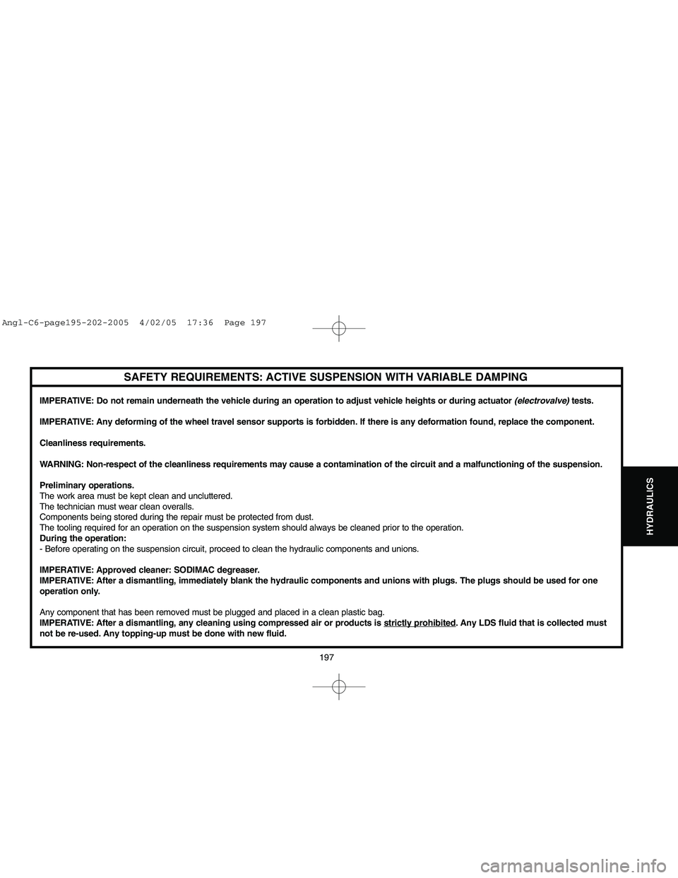
IMPERATIVE: Do not remain underneath the vehicle during an operation to adjust vehicle heights or during actuator (electrovalve) tests.
IMPERATIVE: Any deforming of the wheel travel sensor supports is forbidden. If there is any deformation found, replace the component.
Cleanliness requirements.
WARNING: Non-respect of the cleanliness requirements may cause a contamination of the circuit and a malfunctioning of the suspension.
Preliminary operations.
The work area must be kept clean and uncluttered.
The technician must wear clean overalls.
Components being stored during the repair must be protected from dust.
The tooling required for an operation on the suspension system should always be cleaned prior to the operation.
During the operation:
- Before operating on the suspension circuit, proceed to clean the hydraulic components and unions.
IMPERATIVE: Approved cleaner: SODIMAC degreaser.
IMPERATIVE: After a dismantling, immediately blank the hydraulic components and unions with plugs. The plugs should be used for one
operation only.
Any component that has been removed must be plugged and placed in a clean plastic bag.
IMPERATIVE: After a dismantling, any cleaning using compressed air or products is strictly prohibited
. Any LDS fluid that is collected must
not be re-used. Any topping-up must be done with new fluid.
Angl-C6-page195-202-2005 4/02/05 17:36 Page 197
Page 204 of 223

Downloaded from www.Manualslib.com manuals search engine 198
HYDRAULICS
SUSPENSION SPHERES: GENERAL SPECIFICATION
Each suspension sphere is identified at "a", by one number and two letters, marked in bold characters:
- The number consists of 2 digits, corresponding to the nitrogen pressure inside the suspension sphere.
- The two lettersidentify the location of the suspension sphere.
Other information marked on the suspension sphere:
- Day of the year of manufacture.
- Year of manufacture.
- Time of manufacture.
- Factory no. of the suspension sphere.
B3BP1BJD
Angl-C6-page195-202-2005 4/02/05 17:36 Page 198
Page 205 of 223

Downloaded from www.Manualslib.com manuals search engine 199
HYDRAULICS
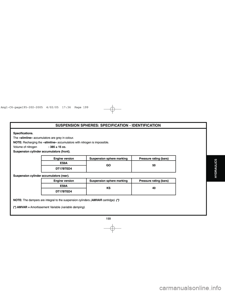
SUSPENSION SPHERES: SPECIFICATION - IDENTIFICATION
Specifications.
The «slimline»accumulators are grey in colour.
NOTE: Recharging the «slimline»accumulators with nitrogen is impossible.
Volume of nitrogen: 385 ± 15 cc.
Suspension cylinder accumulators (front).
Engine version Suspension sphere marking Pressure rating (bars)
ES9A
GO 50
DT17BTED4
Suspension cylinder accumulators (rear).
Engine version Suspension sphere marking Pressure rating (bars)
ES9A
KS 40
DT17BTED4
NOTE: The dampers are integral to the suspension cylinders (AMVARcartridge). (*)
(*) AMVAR =Amortissement Variable (variable damping).
Angl-C6-page195-202-2005 4/02/05 17:36 Page 199
Page 206 of 223

Downloaded from www.Manualslib.com manuals search engine 200
HYDRAULICS
SUSPENSION SPHERES: SPECIFICATION - IDENTIFICATION
Stiffness regulator accumulators (front).
NOTE:The dampers are integral to the hydractive regulator.
Engine version Suspension sphere marking Pressure rating (bars)
ES9A
KR 70
DT17BTED4
Stiffness regulator accumulators (rear).
NOTE:The dampers are integral to the hydractive regulator.
Engine version Suspension sphere marking Pressure rating (bars)
ES9A
KS 40
DT17BTED4
The suspension cylinders on the same axle have to be equipped with the same type of suspension accumulators.
IMPORTANT: Tightening torque for the suspension accumulators : 2,7 ± 0,5 m.daN.
Angl-C6-page195-202-2005 4/02/05 17:36 Page 200
Page 207 of 223
![CITROEN C6 2005 Owners Manual Downloaded from www.Manualslib.com manuals search engine 201
HYDRAULICS
DE-PRESSURISING THE HYDRAULIC SUSPENSION CIRCUITTools.
[1] PROXIAstation: 4165-T
[2] LEXIAstation: 4171-T
De-pressurisation.
NOT CITROEN C6 2005 Owners Manual Downloaded from www.Manualslib.com manuals search engine 201
HYDRAULICS
DE-PRESSURISING THE HYDRAULIC SUSPENSION CIRCUITTools.
[1] PROXIAstation: 4165-T
[2] LEXIAstation: 4171-T
De-pressurisation.
NOT](/img/9/57744/w960_57744-206.png)
Downloaded from www.Manualslib.com manuals search engine 201
HYDRAULICS
DE-PRESSURISING THE HYDRAULIC SUSPENSION CIRCUITTools.
[1] PROXIAstation: 4165-T
[2] LEXIAstation: 4171-T
De-pressurisation.
NOTE:It is possible to de-pressurise the suspension by individual axle.
Using a diagnostic tool.
Start the engine.
Place the height control in the «LOW»position.
Wait for the vehicle height to reach the position required.
Stop the engine.
Connect the diagnostic tool [1]or [2]to the vehicle's diagnostic socket.
Switch on the ignition.
Carry out a global test.Go into the menu:
- Suspension.
- De-pressurisation.
Follow the instructions displayed on the screen.
Wait for the vehicle's suspension to sink completely.
NOTE:This operation takes around 3 minutes.
Switch off the ignition.
Disconnect the battery.
Without a diagnostic tool.
IMPERATIVE: Any LDS fluid that is collected must not be re-used.
NOTE:Collect the LDSfluid in order to keep the work area clean.
Respect the environment.
Start the engine.
Place the height control in the «LOW»position.
Stop the engine.
Angl-C6-page195-202-2005 4/02/05 17:36 Page 201
Page 208 of 223

Downloaded from www.Manualslib.com manuals search engine 202
HYDRAULICS
DE-PRESSURISING THE HYDRAULIC SUSPENSION CIRCUIT
Front suspension:Undo the pressure release screw (1)by one turn.
Wait for the pressure in the hydraulic circuit to drop fully.
Rear suspension:Undo the pressure release screw (2)by one turn.
Wait for the pressure in the hydraulic circuit to drop fully.
B3FP7HDDB3BP1BED
Angl-C6-page195-202-2005 4/02/05 17:36 Page 202
Page 209 of 223

Downloaded from www.Manualslib.com manuals search engine 203
AIR
CONDITIONING
capacity
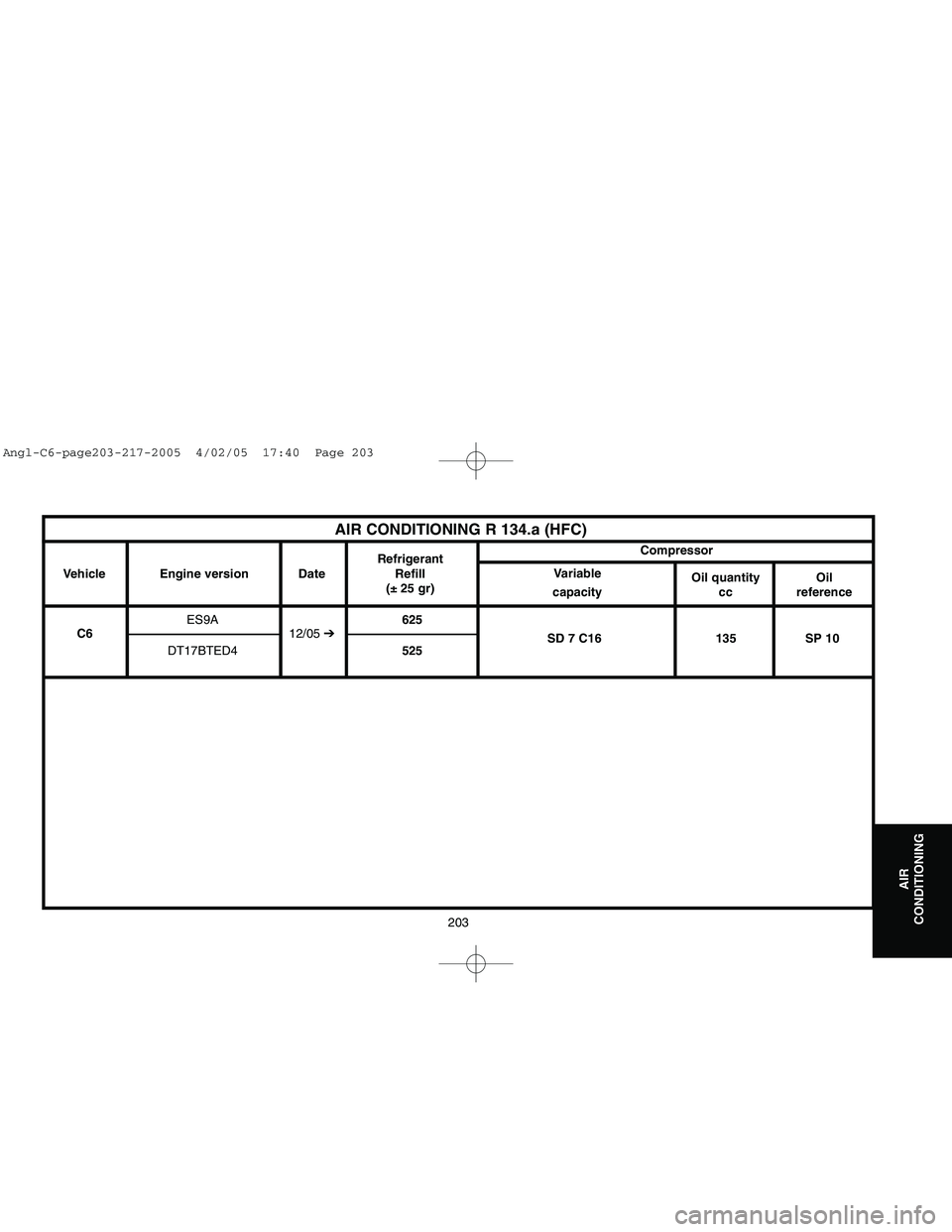
AIR CONDITIONING R 134.a (HFC)
Vehicle
ES9A625
C612/05 ➔
SD 7 C16 135 SP 10
DT17BTED4525 Engine version DateRefrigerant
Refill
(± 25 gr)Compressor
Variable
Oil quantity
ccOil
reference
Angl-C6-page203-217-2005 4/02/05 17:40 Page 203
Page 210 of 223

Downloaded from www.Manualslib.com manuals search engine Compressor
The variable capacity air conditioning compressor has external control.
The internal pneumatic valve is replaced by an external electrovalve.Condenser
The condenser has a cylinder incorporating the function of aircon fluid
reservoir and with integral filtering cartridge.
NOTE: The filtering cartridge is not interchangeable.
SPECIAL FEATURES: AIR CONDITIONING SYSTEM
204
AIR
CONDITIONING
Angl-C6-page203-217-2005 4/02/05 17:40 Page 204