engine Citroen CX 1981 1.G Workshop Manual
[x] Cancel search | Manufacturer: CITROEN, Model Year: 1981, Model line: CX, Model: Citroen CX 1981 1.GPages: 394
Page 181 of 394
Downloaded from www.Manualslib.com manuals search engine 2
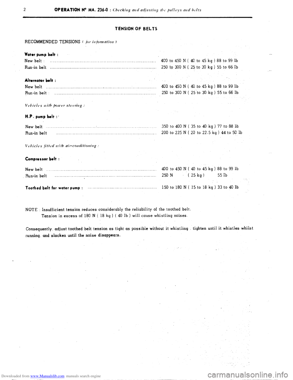
TENSION OF BELTS
RECOMMENDED TENSIONS f /or i//jormation I
Water pump belt :
New belt : ........................................... ................................................. 400 to 450 N ( 40 to 45 kg ) 88 to 99 lb
Run-in belt ...................................................................................... 250 to 300 N ( 25 to 30 kg ) 55 to 66 Ib
Alternator belt :
New belt ......................................................................................... 400 to 450 N ( 40 .to 45 kg ) 88 to 99 lb
Run-in belt .................................................................................. 250 to 300 N ( 25 to 30 kg ) 55 to 66 Ib
Vchicic)s with power slcvring :
H.P. pump belt :’
New belt ........................................................................................... 350 to 400 N ( 35 to 40 kg ) 77 to 88 lb
Run-in belt ............................................................................... 200 to 225 N ( 20 to 22.5 kg ) 44 to 50 lb
Compressor belt :
New belt ......................................................................... ............... 400 to 450 N ( 40 to 45 kg ) 88 to 99 lb
Run-in belt 2% N
..................................................................................
( 25 kg 1 55 Ib
Toothed belt for water pump : ........................................................ 150to180N( 15to18kg)33to40lb
NOTE : Insufficient tension reduces considerably the reliability of the toothed belt.
Tension in excess of 180 N ( 18 kg ) ( 40 Ib ) will cause whistling noises.
Consequently. adjust toothed belt tension as tight as possible without it whistling tighten until it whistles whilst
running. and slacken until the noise disappears.
Page 182 of 394
Downloaded from www.Manualslib.com manuals search engine CLUTCH
OPERATION No MA. 312-00 : (:l,n~nc/cristics nt~d spccinf jc’n/lIrc,s oi r/l<, p~,(jnl--op~,rnlen
Op. MA. 312-00 1
Clll Ich ,ncJ chnr,ism
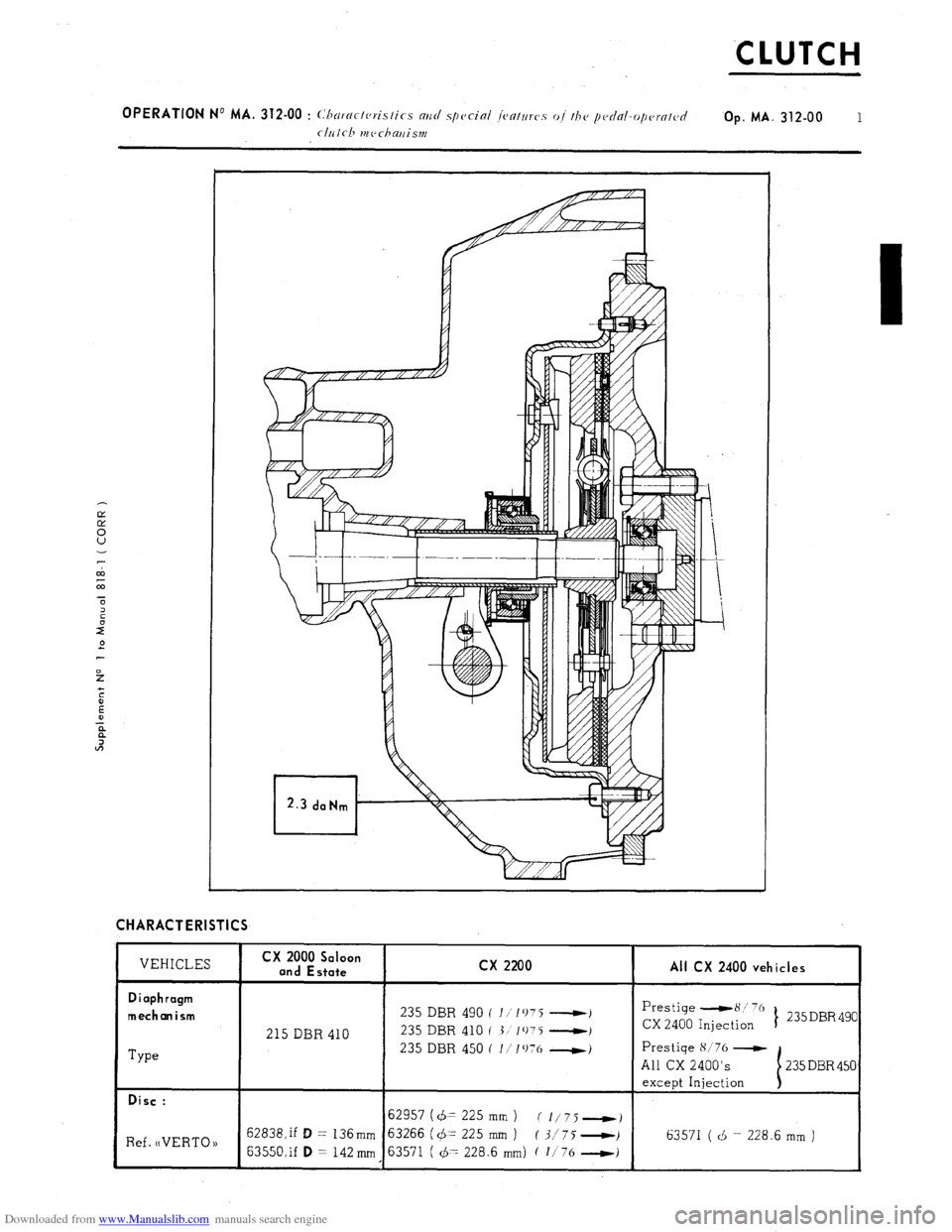
CHARACTERISTICS
VEHICLES CX 2000 Saloon
and Estate
Diaphragm
mechanism
Type 215 DBR 410
Disc :
Ref. (tVERT0 )) 62838,if D = 136mm
63550.if D = 142 mm cx 2200
All CX 2400 vehicles
I
235 DBR 490 ( I/‘1075 ----t)
235 DBR 410 I 3) 1075 ---t)
235 DBR 450 ( l/Iv76 w)
62957 (d= 225 mm ) (l/75-)
63266 (q5- 225 mm ) ( 3/75 0)
63571 ( 47 228.6 mm) ( l/76 -1
Prestige -8:’ 76
CX 2400 Injection t 235 DBR 490
Prestige K/76 -t
All CX 2400’s
except Injection
63571 ( d = 228.6 mm )
Page 183 of 394

Downloaded from www.Manualslib.com manuals search engine 2 OPERATION No MA. 312-00 : Characteristics ntrd special featttws o/ thc~ pedal-operatd
clrilcl~ it~c~chattisttr
Replacing the disc :
- With 235 DBR 490 or 235 DBR 450 mechanisms. fit a N VERTO H disc, ref. no 63571 ( i = 228.6 mm 1
- With 235 DBR 410 mechanism, fit a (( VERTO N disc. ref. no 63266 ( 4 = 225 mm 1.
Replacing the mechanism :
- Replace the 235 DBR 490 and 235 DBR 410 mechanisms, by a 235 DBR 450 mechanism, with a (( VERTO P)
disc, ref. no 63571 ( + 1228.6 mm ).
Thrust bearing : self-cent&in9
Ill. SPECIAL FEATURES
Clearance between thrust bearing and diaphragm : 1 to 1.5 mm
Page 184 of 394
Downloaded from www.Manualslib.com manuals search engine OPERA1
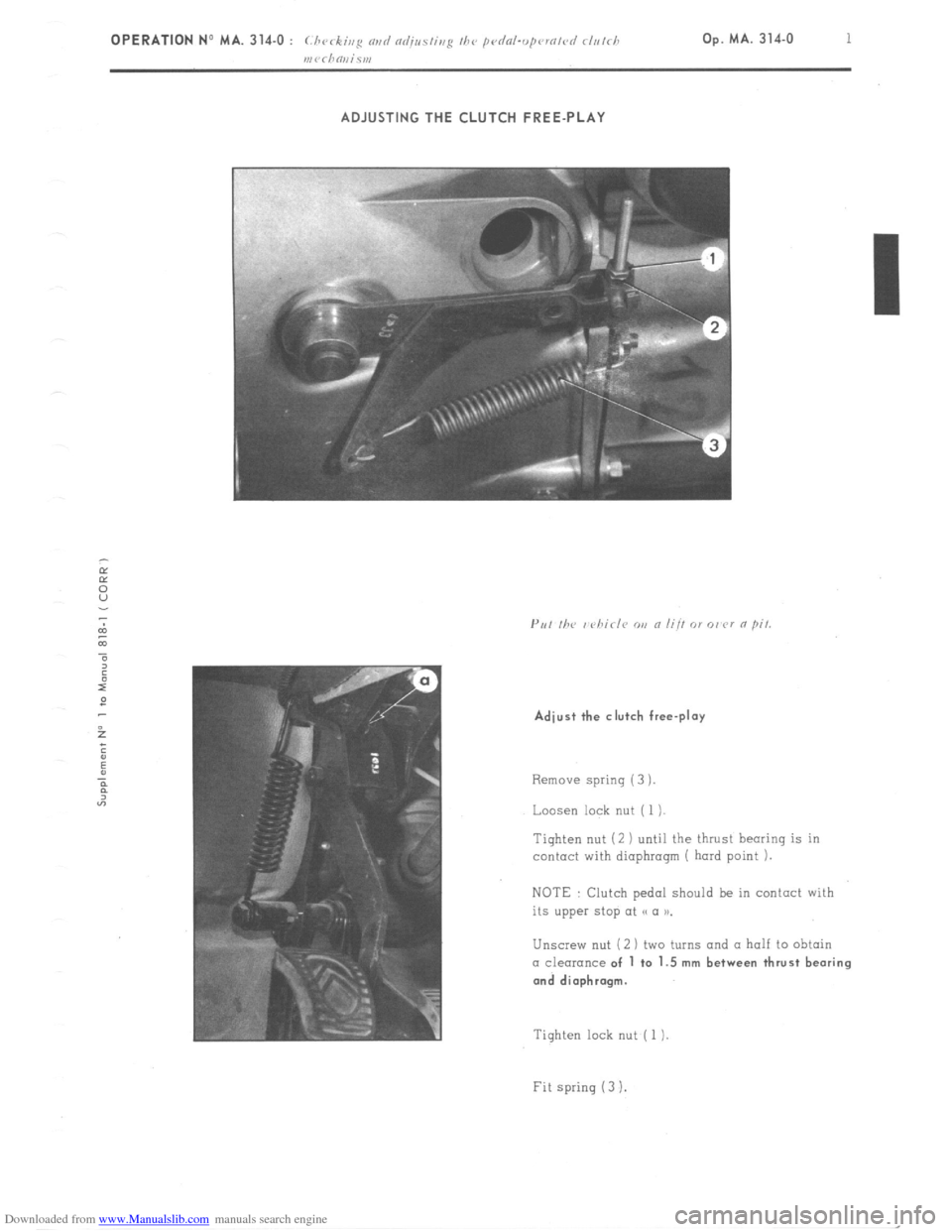
ADJUSTING THE CLUTCH FREE-PLAY
Adjust the clutch free-play
Remove spring (3 ).
Loosen lock nut ( 1 ).
Tighten nut (2 ) until the thrust hearing is in
contact with diaphragm ( hard point 1.
NOTE : Clutch pedal should be in contact with
its upper stop at << (I n.
Unscrew nut (2 1 two turns and a half to obtain CI clearance of 1 to 1.5 mm between thrust bearing
and diaphragm.
Tighten lock nut ( 1 )
Fit spring (3 I.
Page 185 of 394
Downloaded from www.Manualslib.com manuals search engine TORQUE CONVERTER
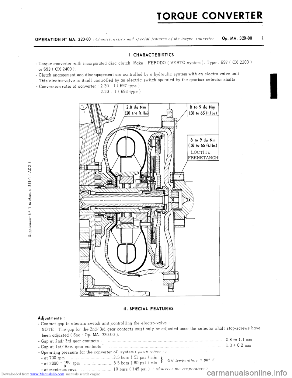
I. CHARACTERISTICS
- Torque converter with incorporated disc clutch. Make FERODO ( VERTO system ). Type 697 ( CX 2200 )
or 693 ( CX 2400 ).
_ Clutch engagement and disengagement are controlled by a hydraulic system with an electro valve unit
I This electro-va,lve is itself controlled by an electric switch operated by the gearbox selector shafts.
- Conversion ratio of converter 2 30 1 ( 697 type )
2.20 1 ( 693 type ) II. SPECIAL FEATURES
Adiustments :
- Contact gap in electric switch unit ,controlling the electro-valve
NOTE The gap for the 2nd/ 3rd gear contacts must only be adjusted once the selector shaft stop-screws have
been adjusted ( See Op. MA. 330-00 ),
- Gap at 2nd/ 3rd gear contacts 0 8 to 1.1 mm
- Gap at lst/ Rev. gear contacts ’ 13+02mm
. . . . . . . . . . . . .._.......
- Operating pressure for the converter oil system c /)IIv//~ ~c,I//v/I J :
- at 700 rpm 3.5 bars ( 51 psi ) min
_ at 2000 i A00 rpm 5.5 bars ( 80 psi 1 min 1
Oil l,c~~~i/~~~i’NItrrc~ 80: (.
- at maximum revs .,......... 10 bars ( 145 psi ) ( II./IN/<‘I (‘7 /h(, I<,ml,(a,‘flt~ro )
Page 186 of 394
Downloaded from www.Manualslib.com manuals search engine - Calibration of thermal switch for temperature warning lamp .__._... 135 ? 3” C
- Type of oil . . .._..__.._._..___._._._._._.................,,.........._..._..._................. TOTAL (( FLUIDE 1) T
- Total capacity f
iur//rdiir/g ~~arhos ) .._._.._.......................... 5.5 litres ( 9.7,pts )
- Interchanqeable suction filter
- Filling the converter during fitting. actuate the electro-valve a dozen times.
Tightening torques :
- Electra-valve fixing screw ............................................................ 2.8 daNm ( 20 l/2 ft.Ib )
- Union-screw for oil pipe ............................................................... 3 to 3.5 daNm ( 21 l/ 2 to 25 l/ 2 ft.Ib )
- Suction filter .................................................... ........... ............. 3.5 to 4 daNm ( 25 l/2 to 29 ft.Ib )
- Contact fixing screws ................................................................... 0.2 to 0.3 daNm ( 1 11 2 to 2 ft.lb )
IMPORTANT : In the course of repairs, it is permissible to replace a 697-type ( .CX 2200 ) converter by a 693-type
( CX 2400 ) one.
However, the reverse operation ( replacing a 693-type by a 697-type converter ) is prohibited.
Page 187 of 394

Downloaded from www.Manualslib.com manuals search engine OPERATION No MA. 320-00 : (.l~n~~/(-/(,~iz/i(-c m/d s/we-in: ~o~///,w. o/ //I<, /r,t~///c cc,,,, or/r r Op. MA. 32Oz.00 3
III. OPERATIONAL DIAGRAM OF TORQUE CONVERTER
Engine running, gear-lever in neutral
Page 188 of 394

Downloaded from www.Manualslib.com manuals search engine E ngine running, one qear enqaqed
I
I 7
I- I O 1
--- ---
Page 189 of 394
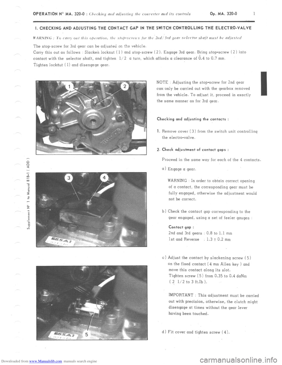
Downloaded from www.Manualslib.com manuals search engine OPERATION No MA. 320-O : Checking md czdjssting fhe ronw’rtcv artd its corrtrols Op. MA. 320.0 1 I. CHECKING AND ADJUSTING THE CONTACT GAP IN THE SWITCH CONTROLLING THE ELECTRO-VALVE
The stopscrew for 3rd gear can be adjusted SK the vehicle.
Carry this out as follows : Slacken locknut ( 1 ) and stopscrew (2 ). Engage 3rd gear. Bring stop-screw i 2 1 into
contact with the selector shaft. and tighten l/2 a turn, which affords a clearance of a.4 to Cl.7 mm.
Tighten lockfiut ( 1) and disengage gear.
NOTE : Adjusting the stop-screw for 2nd gear
con only be carried out with the gearbox removed
from the vehicle. To adjust it, proceed in exactly I
the same manner as for 3rd gear. Checking and adjusting the contacts :
1.
Remove cover ( 3) from the switch unit controliinq
the electro-valve. 2. Check adjustment of contact gaps :
Proceed in the same way far each of the 4 contacts.
a) Engage a gear.
WARNING In order to obtain correct opening
of a contact, the corresponding gear must be
fully engaged. otherwise the adjustment would
not be correct.
b) Check the contact gap corresponding to the
gear engaged, using a set of feeler gauges : Contact gap :
2nd
and 3rd gears 0.8 to 1.1 mm
1st and Reverse 1.3 ? 0.2 mm
c 1 Adjust the contact by slackening screw ( 5)
on the fixed contact (4 mm Allen key ) and
move this contact along its slot.
Tighten screw ( 5) from 0.35 to 0.4 doNm
( 2 l/2 to 3 ft.Ib ).
IMPORTANT : This adjustment must be carried
out with precision, otherwise, the clutch might
disengage at times without the gear lever
having been touched.
d 1 Fit cover and tighten screw ( 4 1.
Page 190 of 394

Downloaded from www.Manualslib.com manuals search engine GEARBOX
4-SPEED MANUAL GEARBOX
I. CHARACTERISTICS
1. Gear ratios :
NOTE
Speeds are given for vehicles equipped with 185 SR 14 ZX, 185 SR 14 XZX or 185 HR XVS tyres. the
rolling circumference of which is 1 970 m under load.
a) cc All CX Vehicles u gearbox :
I
Gears
I Gearbox ratios
I 1st
I ( 12138 ) 3 1666 1
I 2nd
I ( 18133) 1.8333 1
I 3rd
I ( 30/34) 1 1333 1 Final
drive ratio Overall ratios
I 8 7434 1
13/ 62
4 769 1
I 15.3411 1 Speed at IOO? rpm
in km/h (mph)
7 82 ( 4.89 )
13 51 (8 44 1
21 86 ( 13 66 !
Speedometer drive ratio 5 12 7 85 ( 4.95 1
b) ss Economy option D gearbox on CX 2000 -1 107j
Gears
1st
2nd
3rd
4th
Reverse Gearbox ratios
( 12/38
) 3 1666 1
( 18/33 ) 1.8333 1
( 3W34 1 1.1333
1
( 36/27 ) c,75 1
( 13/ 41) 3 1538 1 Final
drive ratio Overall ratios Speed at 1002 rpm
in km/ h ( mph 1
13 7973 1 8.56 ( 5 35 1
7 9879 1 14.79
( 9.24 ! I
I
14161
4357 1
4 9379 1 23.93
i 14.96 )
3 2678 1
13.7415 1 ( 5.38
Speedometer drive ratio 5 x 11