CITROEN CX 1988 Service Manual
Manufacturer: CITROEN, Model Year: 1988, Model line: CX, Model: CITROEN CX 1988Pages: 648, PDF Size: 95.8 MB
Page 251 of 648
1 rnA 210.00/4a
#
@Eia
137
~ 2
I 141 136
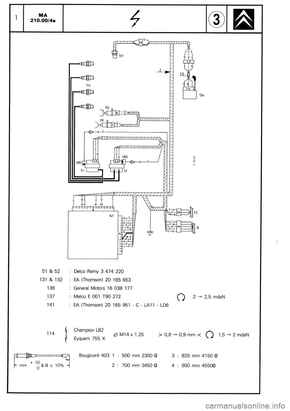
51 &52 : Delco Remy 3 474 220
131 & 132 : EA (Thomson) 20 165 653
136 : General Motors 16 038 177
137 : Melco E 001 T90 272 0 2-1
141 : E!A (Thomson) 20 165 951 - C - IA1 1 - LD6
b 2,5 mdaN
114 Champion L82
Eyquem 755 X 0 Ml4 x 1,25 > 0,8 -+ 0,9 mm <
0 1,5 -+ 2 mdaN
Bougicord 403 1 : 500 mm 2300 Q 3 : 825mm4150Q
2 : 700 mm 3450 $I 4 : 900 mm 455OQ
Page 252 of 648
asI f MA 2 21 O.O0/4a
IC
~ I
82 F;
r----------- E
M TMv
SM! Iv J
Kz1 5Ml I Z
z z z z z
I( AEI
dE B
1 ;
E
3 \,
LLII
.Vl
;-,
----I
46
Z
81
B9
4
1~~11~ 21 [NI~IIN~IIN 31
i?B 7 I.41
? ?
8531
Page 253 of 648
1 MA
210.0014b
u
I
.
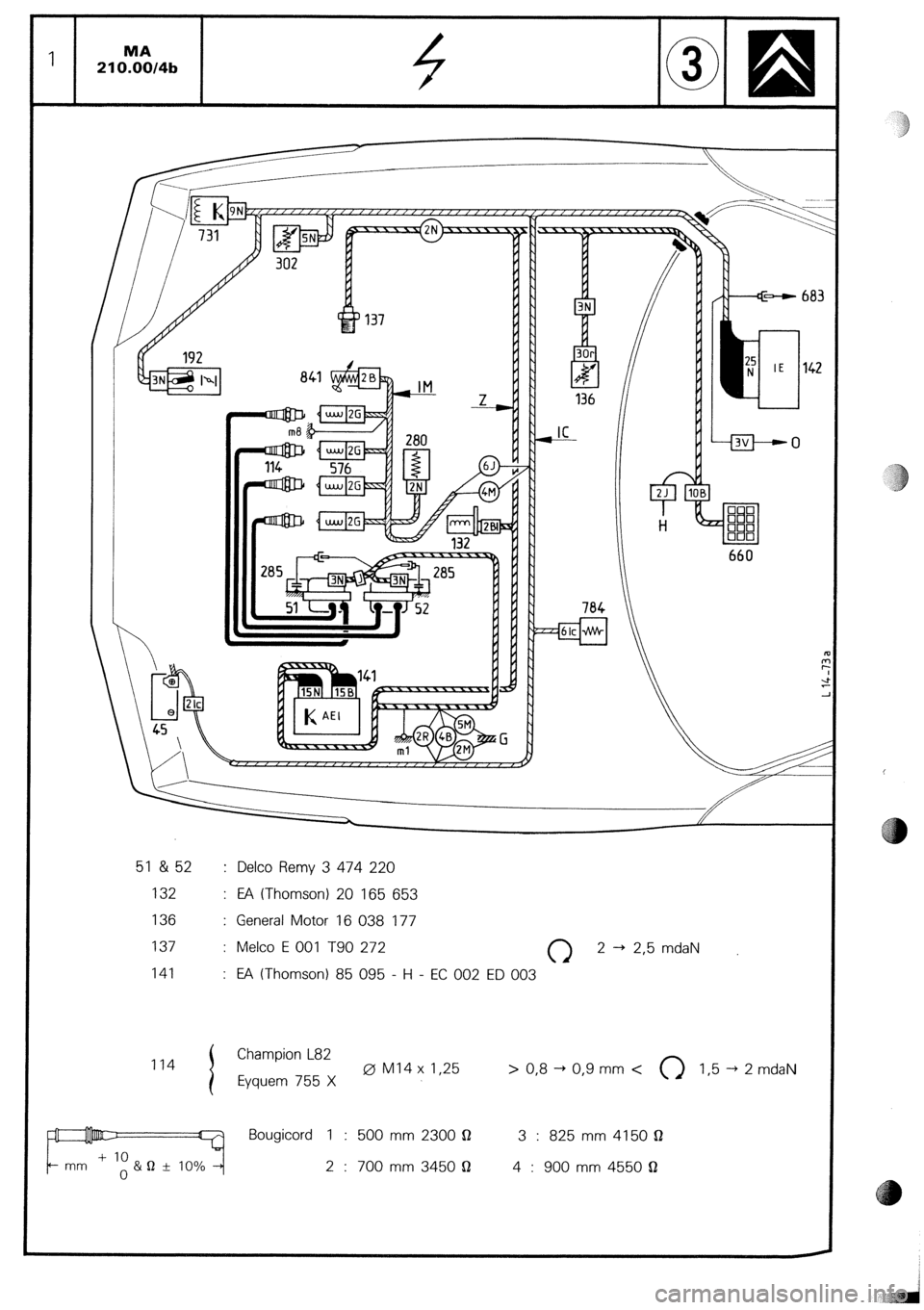
51 &52 : Delco Remy 3 474 220
132
: EA (Thomson) 20 165 653
136 : General Motor 16 038 177
137 : Melco E 001 T90 272
0 2 -+ 2,5 mdaN
141
: E!A (Thomson) 85 095 - H - EC 002 ED 003
114
I Champion L82
Eyquem 755 X 0 Ml4 x I,25 > 0,8 + 0,9 mm <
0 I,5 -+ 2 mdaN
g Jlllllu&~ 7 Bougicord 1 : 500 mm 2300 Q
3 : 825 mm 4150 Q
+ 10
+- mm
o&" f 10% -+ 2 : 700 mm 3450 Q
4 : 900 mm 4550 Q
1)
Page 254 of 648
MA 21 O.O0/4b 2
I I I I I I I I I I I I I 1 I I I I I I I I I
1 2 3 4 S 6 1 8 9 10 11 12 13 14 15 16 17 li )l9 20 21 22 23 2~ :S :6 :7 i.3 :9 30 :I 312 :3 :L :S
8531
Page 255 of 648
CHECKING THE TRANSLSTORISED IGNlTlON
Page 256 of 648
CHECKlNG THE TRANSISTORISED IGNITION
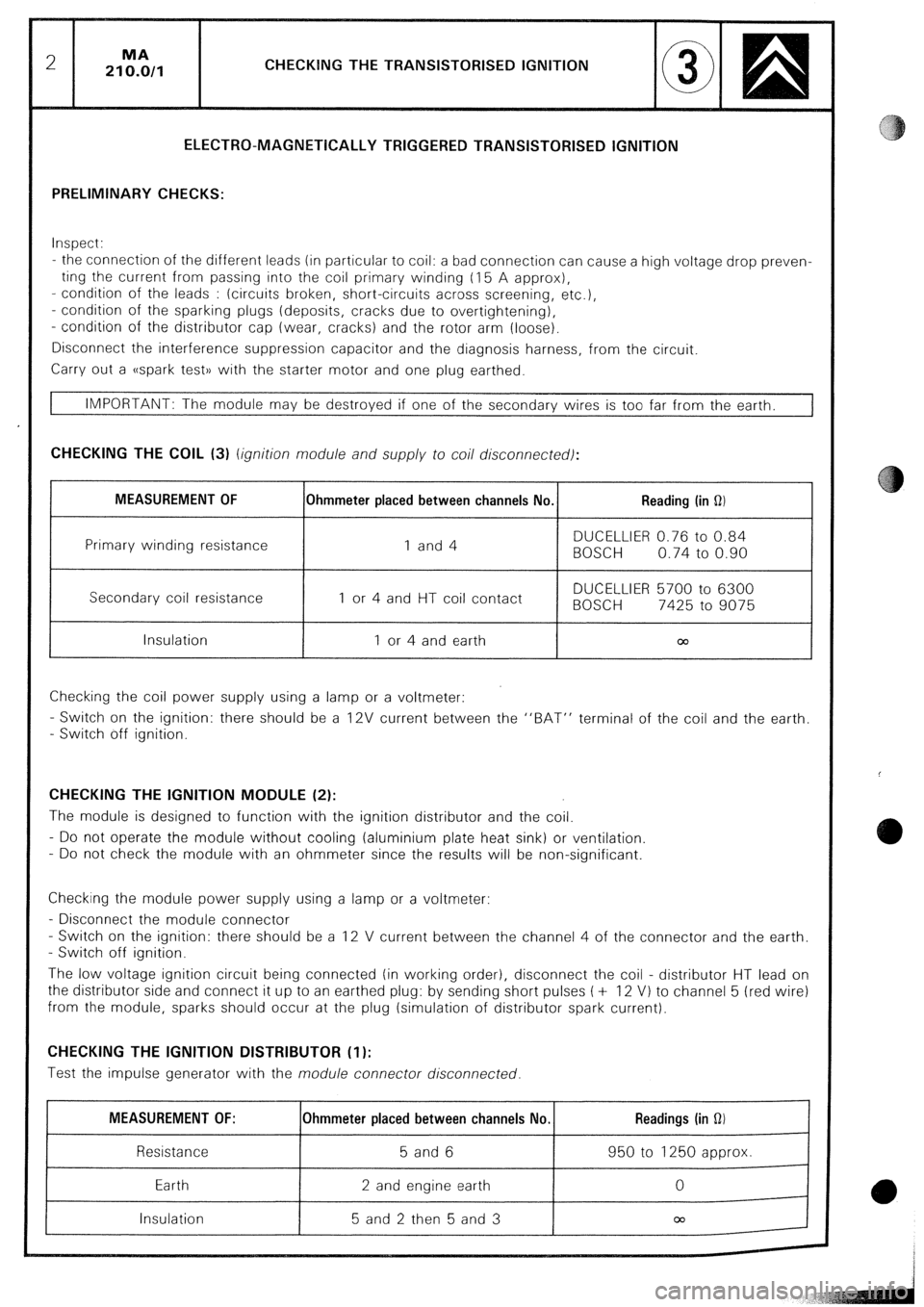
ELECTRO-MAGNETICALLY TRIGGERED TRANSISTORISED IGNITION
PRELIMINARY CHECKS:
Inspect:
- the connection of the different leads (in particular to coil: a bad connection can cause a high voltage drop preven-
ting the current from passing into the coil primary winding (I 5 A approx),
- condition of the leads : (circuits broken, short-circuits across screening, etc.),
- condition of the sparking plugs (deposits, cracks due to overtightening),
- condition of the distributor cap (wear, cracks) and the rotor arm (loose).
Disconnect the interference suppression capacitor and the diagnosis harness, from the circuit.
Carry out a ((spark test)) with the starter motor and one plug earthed.
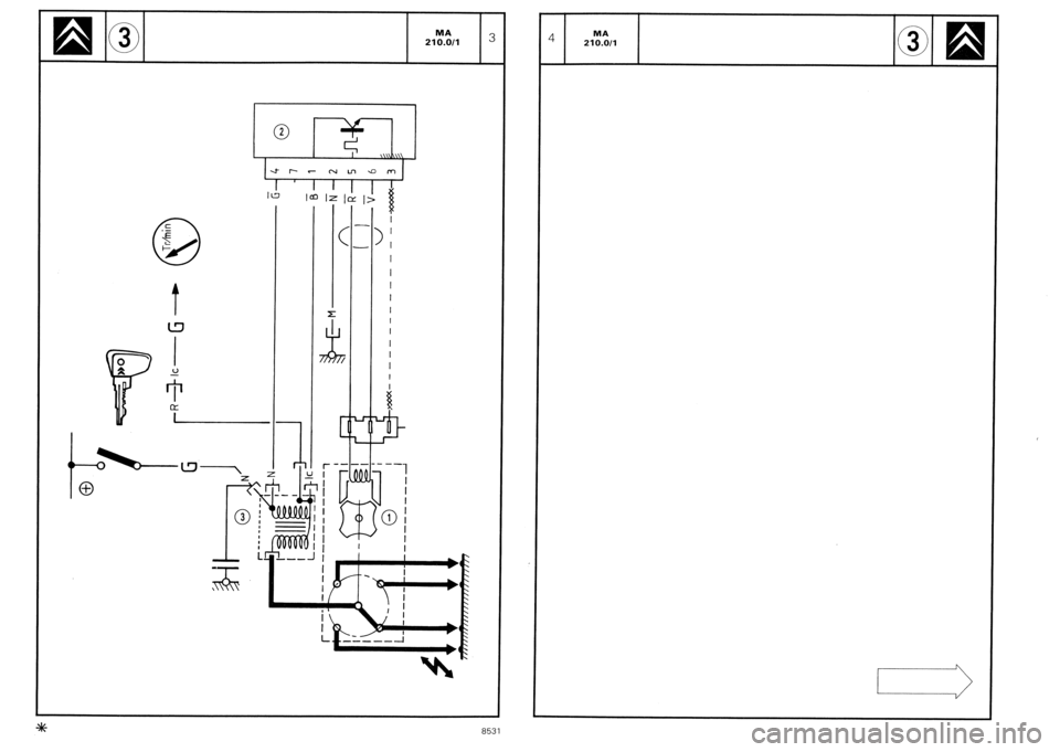
IMPORTANT: The module may be destroyed if one of the secondary wires is too far from the earth. CHECKING THE COIL (3) (ignition module and supply to coil disconnected):
MEASUREMENT OF Ohmmeter placed between channels No. Reading (in 0)
Primary winding resistance 1 and 4 DUCELLIER 0.76 to 0.84
BOSCH 0.74 to 0.90
Secondary coil resistance 1 4 and HT coil contact DUCELLIER 5700 to 6300
or
BOSCH 7425 to 9075
Insulation 1 or 4 and earth 00
Checking the coil power supply using a lamp or a voltmeter:
- Switch on the ignition: there should be a 12V current between the “BAT” terminal of the coil and the earth
- Switch off ignition. CHECKING THE IGNITION MODULE (2):
The module is designed to function with the ignition distributor and the coil.
- Do not operate the module without cooling (aluminium plate heat sink) or ventilation
- Do not check the module with an ohmmeter since the results will be non-significant.
Checking the module power supply using a lamp or a voltmeter:
- Disconnect the module connector
- Switch on the ignition: there should be a 12 V current between the channel 4 of the connector and the earth.
- Switch off ignition.
The low voltage ignition circuit being connected (in working order), disconnect the coil - distributor HT lead on
the distributor side and connect it up to an earthed plug: by sending short pulses ( + 12 VI to channel 5 (red wire)
from the module, sparks should occur at the plug (simulation of distributor spark current). CHECKING THE IGNITION DISTRIBUTOR (1):
Test the impulse generator with the module connector disconnected. MEASUREMENT OF:
Resistance
Earth
Insulation Ohmmeter placed between channels No. 5 and 6
2 and engine earth
5 and 2 then 5 and 3 Readings (in Q) 950 to 1250 approx.
0
m
,
Page 257 of 648
Page 258 of 648
Page 259 of 648
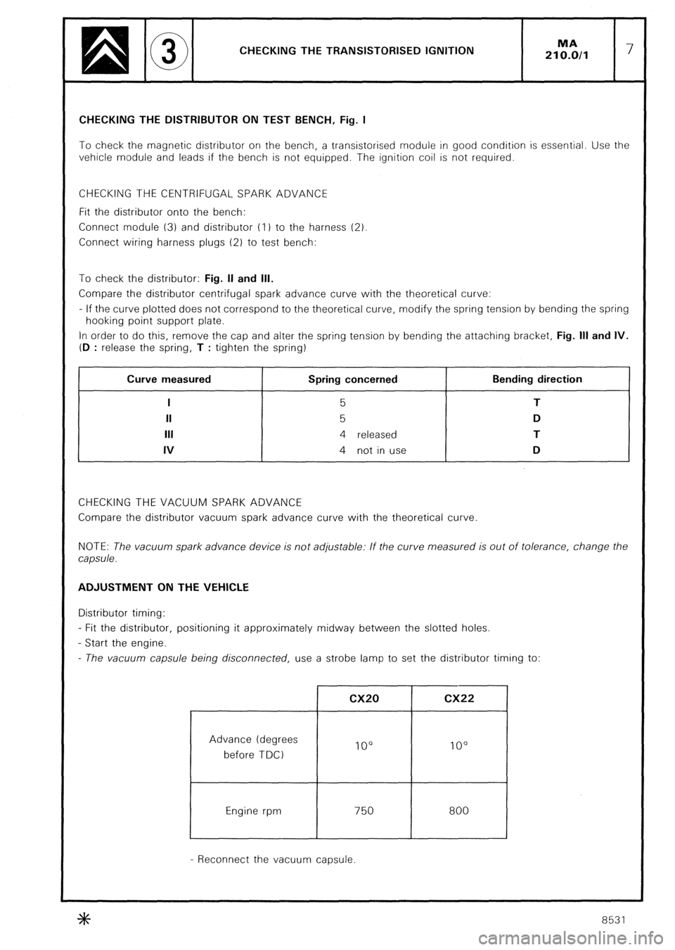
CHECKING THE TRANSISTORISED IGNITION MA
210.0/l 7 CHECKING THE DISTRIBUTOR ON TEST BENCH, Fig. I
To check the magnetic distributor on the bench, a transistorised module in good condition is essential. Use the
vehicle module and leads if the bench is not equipped. The ignition coil is not required.
CHECKING THE CENTRIFUGAL SPARK ADVANCE
Fit the distributor onto the bench:
Connect module (3) and distributor (I 1 to the harness (2)
Connect wiring harness plugs (2) to test bench:
To check the distributor: Fig. II and Ill.
Compare the distributor centrifugal spark advance curve with the theoretical curve:
- If the curve plotted does not correspond to the theoretical curve, modify the spring tension by bending the spring
hooking point support plate.
In order to do this, remove the cap and alter the spring tension by bending the attaching bracket, Fig. Ill and IV.
(D
: release the spring, T : tighten the spring) , Curve measured
I
II
Ill
IV Spring concerned
5
5
4 released
4 not in use Bending direction
T
D
T
D
CHECKING THE VACUUM SPARK ADVANCE
Compare the distributor vacuum spark advance curve with the theoretical curve
NOTE: The vacuum spark advance device is not adjustable: If the curve measured is out of tolerance, change the
capsule. ADJUSTMENT ON THE VEHICLE
Distributor timing:
- Fit the distributor, positioning it approximately midway between the slotted holes.
- Start the engine.
- The vacuum capsule being disconnected, use a strobe lamp to set the distributor timing to:
Advance (degrees
before TDC)
Engine rpm cx20 cx22
IO0 lo0
750
I 800
- Reconnect the vacuum capsule.
8531
Page 260 of 648
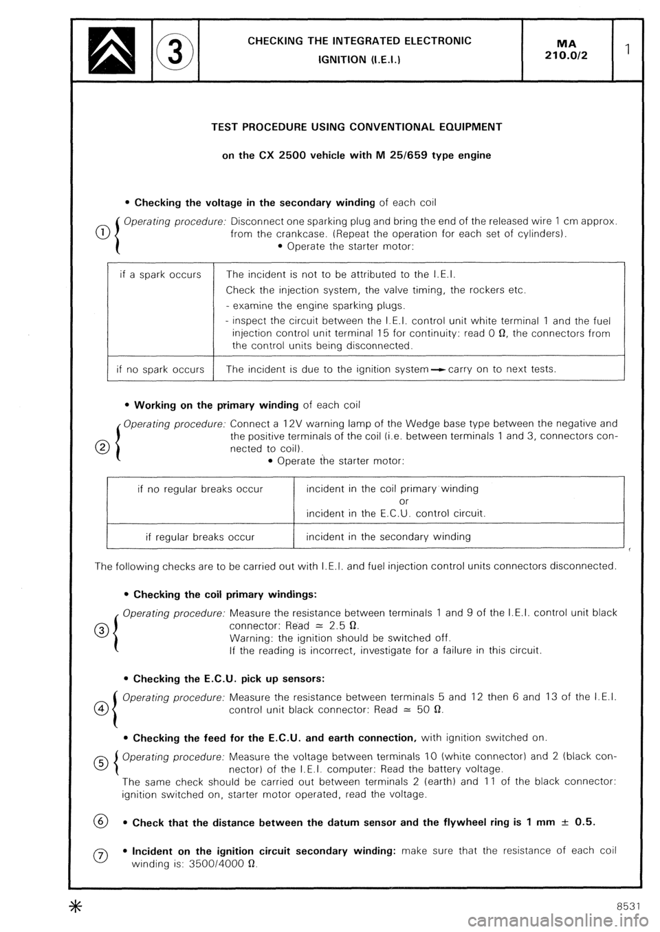
CHECKING THE INTEGRATED ELECTRONlC
IGNITION (I.E.I.)
TEST PROCEDURE USING CONVENTIONAL EQUIPMENT
on the CX 2500 vehicle with M 25/659 type engine
l Checking the voltage in the secondary winding of each coil
0 Operating procedure: Disconnect one sparking plug and bring the end of the released wire 1 cm approx
from the crankcase. (Repeat the operation for each set of cylinders).
l Operate the starter motor:
if a spark occurs The incident is not to be attributed to the I.E.I.
Check the injection system, the valve timing, the rockers etc.
- examine the engine sparking plugs.
- inspect the circuit between the I.E.I. control unit white terminal 1 and the fuel
injection control unit terminal 15 for continuity: read 0 0, the connectors from
the control units being disconnected.
if no spark occurs The incident is due to the ignition system--ccarry on to next tests.
l Working on the primary winding of each coil
Operating procedure: Connect a 12V warning lamp of the Wedge base type between the negative and
0 the positive terminals of the coil (i.e. between terminals 1 and 3, connectors con-
netted to coil).
l Operate the starter motor:
if no regular breaks occur incident in the coil primary winding
or
incident in the E.C.U. control circuit.
if regular breaks occur incident in the secondary winding
The following checks are to be carried out with I.E.I. and fuel injection control units connectors disconnected.
l Checking the coil primary windings:
Operating procedure: Measure the resistance between terminals 1 and 9 of the I.E.I. control unit black
0 connector: Read = 2.5 0.
Warning: the ignition should be switched off.
If the reading is incorrect, investigate for a failure in this circuit.
l Checking the E.C.U. pick up sensors:
co Operating procedure: Measure the resistance between terminals 5 and 12 then 6 and 13 of the I.E.I.
control unit black connector: Read = 50 a.
l Checking the feed for the E.C.U. and earth connection, with ignition switched on
Operating procedure: Measure the voltage between terminals IO (white connector) and 2 (black con-
nector) of the I.E.I. computer: Read the battery voltage.
The same check should be carried out between terminals 2 (earth) and 11 of the black connector:
ignition switched on, starter motor operated, read the voltage.
69 l Check that the distance between the datum sensor and the flywheel ring is 1 mm + 0.5.
0 l Incident on the ignition circuit secondary winding: make sure that the resistance of each coil
winding is: 350014000 a.
8531