light CITROEN DS3 2018 Handbook (in English)
[x] Cancel search | Manufacturer: CITROEN, Model Year: 2018, Model line: DS3, Model: CITROEN DS3 2018Pages: 248, PDF Size: 8.79 MB
Page 165 of 248

163
Leather
Leather is a natural product. Appropriate
regular care and cleaning is essential for its
durability.
Refer to your vehicle's Maintenance and
Warranty Guide for information on all the
special precautions to observe.
Care of the stickers
These styling stickers are treated to give good
resistance to ageing and tearing.
They have been designed to allow you to
customise your vehicle's bodywork.
Available also as accessories, we recommend
that you have them applied by a
network dealer
or a
qualified workshop.
When washing your vehicle, keep the
high-pressure lance tip at least 30
cm
away from the stickers.
Fabric roof
Before washing the fabric, remove as
much dirt as possible using a soft brush or
a
vacuum cleaner.
We recommend cleaning your vehicle in
an automatic roller-brush car wash.
To avoid damaging the roof, never use
a
high-pressure jet wash.
Allow the vehicle to dry in the shade and
avoid exposing it to direct sunlight.
To remove stains, dab them (never rub
them) with a
sponge and some soapy
water, then immediately rinse the fabric
with clean water.
Immediately remove bird droppings or
plant resins, their caustic nature could
damage the fabric. For regular care of the fabric and to keep
its original appearance, we recommend
using the environmentally friendly product
"Insect remover – all-roof cleaner" from
the "TECHNATURE" range. To obtain this
product, visit your dealer.
Never use chemical products, detergents,
stain removers, solvents, alcohol, petrol,
etc. to clean the fabric.
To waterproof the fabric, use only
waterproofing products specifically for
fabric hoods.
Acoustic air deflector
We recommend that you clean the
acoustic air deflector with care
, using
a
soft brush.
07
Practical information
Page 177 of 248
175
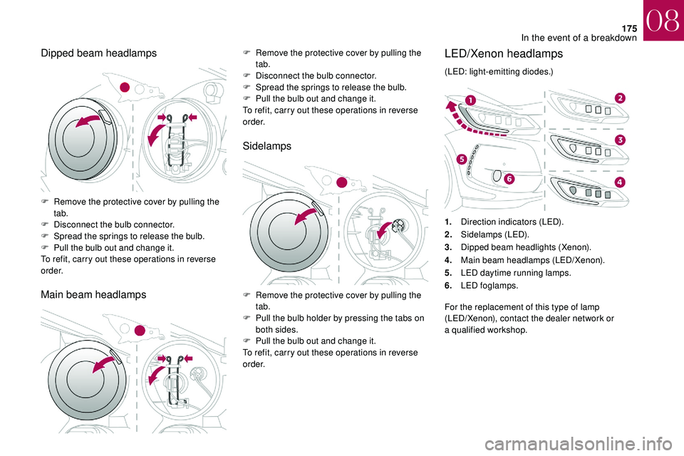
Dipped beam headlamps
Main beam headlampsF Remove the protective cover by pulling the tab.
F
D
isconnect the bulb connector.
F
S
pread the springs to release the bulb.
F
P
ull the bulb out and change it.
To refit, carry out these operations in reverse
o r d e r.
Sidelamps
F Remove the protective cover by pulling the tab.
F
D
isconnect the bulb connector.
F
S
pread the springs to release the bulb.
F
P
ull the bulb out and change it.
To refit, carry out these operations in reverse
o r d e r.
F
R
emove the protective cover by pulling the
tab.
F
P
ull the bulb holder by pressing the tabs on
both sides.
F
P
ull the bulb out and change it.
To refit, carry out these operations in reverse
o r d e r.
LED/Xenon headlamps
(LED: light-emitting diodes.)
1. Direction indicators (LED).
2. Sidelamps (LED).
3. Dipped beam headlights (Xenon).
4. Main beam headlamps (LED/Xenon).
5. LED daytime running lamps.
6. LED foglamps.
For the replacement of this type of lamp
(LED/Xenon), contact the dealer network or
a
qualified workshop.
08
In the event of a breakdown
Page 181 of 248

179
Number plate lamps (LED)
Third brake lamp (4 x W5W bulbs)F Push centrally on the lamp body, while levering it with two screwdrivers to extract it
to the outside.
F
D
isconnect the connector and, if necessary,
the lamp screenwash tube.
F
T
urn the bulb holder corresponding to the
faulty bulb a
quarter turn.
F
P
ull the bulb out and change it.
To refit, carry out these operations in reverse
o r d e r.Third brake lamp (LED)
For the replacement of this type of LED lamp,
contact the dealer network or a qualified
workshop.
F
O
pen the boot.
F
R
emove the two blanking plugs A located
on the lining. For the replacement of this type of light emitting
diode lamp, contact the dealer network or
a
qualified workshop.
08
In the event of a breakdown
Page 182 of 248

180
Interior lighting
Courtesy lamp (1/W5W)
Unclip the cover of courtesy lamp 1 with a fine
s crewdriver, on the control side, to access the
faulty bulb.
Map reading lamps (2/W5W)
Unclip the cover of courtesy lamp 1 . To
access the faulty bulb, unclip the reading lamp
2
partition concerned.
Boot lamp (W5W) Footwell and central storage lighting
(W5W)
Unclip the unit to access the bulb.
Glove box lighting (W5W)Unclip the unit by pushing the base from
behind.
Unclip the unit to access the bulb.
08
In the event of a breakdown
Page 185 of 248
183
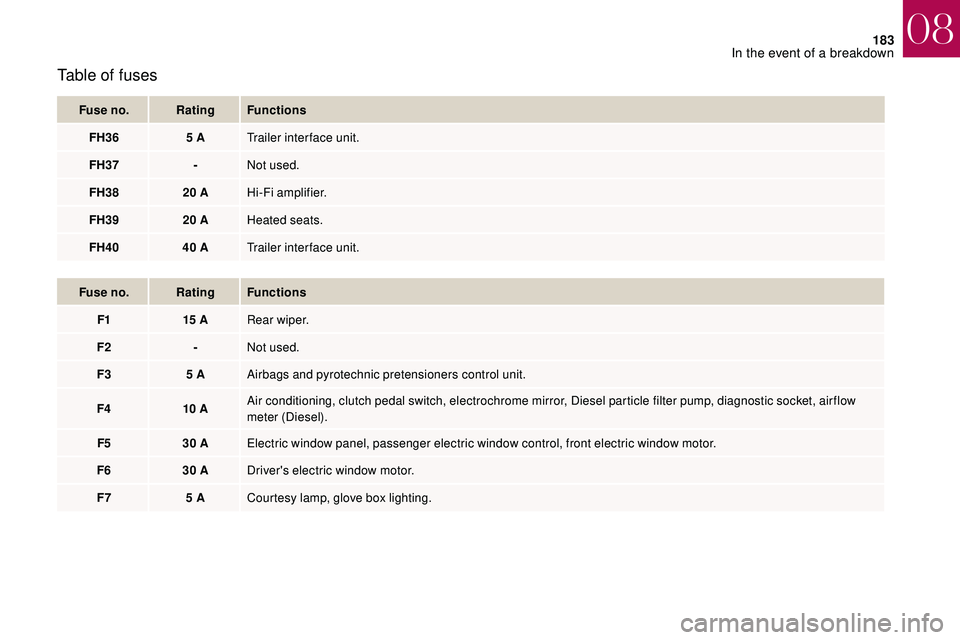
Table of fuses
Fuse no.Rating Functions
FH36 5
ATrailer inter face unit.
FH37 -Not used.
FH38 20
AHi-Fi amplifier.
FH39 20
AHeated seats.
FH40 40
ATrailer inter face unit.
Fuse no. Rating Functions
F1 15
ARear wiper.
F2 -Not used.
F3 5
AAirbags and pyrotechnic pretensioners control unit.
F4 10
AAir conditioning, clutch pedal switch, electrochrome mirror, Diesel particle filter pump, diagnostic socket, air flow
meter (Diesel).
F5 30
AElectric window panel, passenger electric window control, front electric window motor.
F6 30
ADriver's electric window motor.
F7 5
ACourtesy lamp, glove box lighting.
08
In the event of a breakdown
Page 189 of 248
187
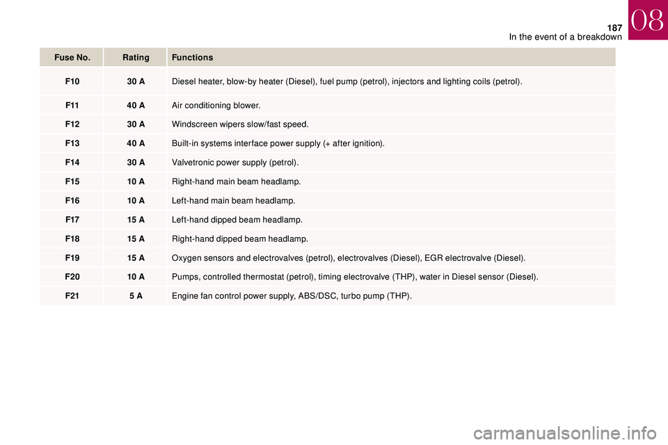
Fuse No.Rating Functions
F10 30
ADiesel heater, blow-by heater (Diesel), fuel pump (petrol), injectors and lighting coils (petrol).
F11 40
AAir conditioning blower.
F12 30
AWindscreen wipers slow/fast speed.
F13 40
ABuilt-in systems inter face power supply (+ after ignition).
F14 30
AValvetronic power supply (petrol).
F15 10
ARight-hand main beam headlamp.
F16 10
ALeft-hand main beam headlamp.
F17 15
ALeft-hand dipped beam headlamp.
F18 15
ARight-hand dipped beam headlamp.
F19 15
AOxygen sensors and electrovalves (petrol), electrovalves (Diesel), EGR electrovalve (Diesel).
F20 10
APumps, controlled thermostat (petrol), timing electrovalve (THP), water in Diesel sensor (Diesel).
F21 5
AEngine fan control power supply, ABS/DSC, turbo pump (THP).
08
In the event of a breakdown
Page 191 of 248
189
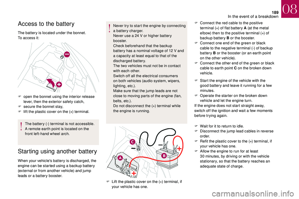
Access to the battery
The battery is located under the bonnet.
To access it:
F
o
pen the bonnet using the interior release
lever, then the exterior safety catch,
F
s
ecure the bonnet stay,
F
l
ift the plastic cover on the (+) terminal.The battery (-) terminal is not accessible.
A remote earth point is located on the
front left-hand wheel arch.
Starting using another battery
When your vehicle's battery is discharged, the
engine can be started using a backup battery
(external or from another vehicle) and jump
leads or a
battery booster. Never try to start the engine by connecting
a
battery charger.
Never use a 24 V or higher battery
b o o s t e r.
Check beforehand that the backup
battery has a nominal voltage of 12 V and
a capacity at least equal to that of the
discharged battery.
The two vehicles must not be in contact
with each other.
Switch off all the electrical consumers
on both vehicles (audio system, wipers,
lighting, etc.).
Make sure that the jump leads are not
close to moving parts of the engine (fan,
belts, etc.).
Do not disconnect the (+) terminal while
the engine is running. F
C
onnect the red cable to the positive
terminal (+) of flat battery A (at the metal
elbow) then to the positive terminal (+) of
backup battery B or the booster.
F
C
onnect one end of the green or black
cable to the negative terminal (-) of backup
battery B or the booster (or an earth point
on the other vehicle).
F
C
onnect the other end of the green or black
cable to earth point C on the broken down
vehicle.
F
L
ift the plastic cover on the (+) terminal, if
your vehicle has one. F
S
tart the engine of the vehicle with the
good battery and leave it running for a few
minutes.
F
O
perate the starter on the broken down
vehicle and let the engine turn.
If the engine does not start straight away,
switch off the ignition and wait a few moments
before trying again.
F
W
ait for it to return to idle.
F
D
isconnect the jump lead cables in reverse
o r d e r.
F
R
efit the plastic cover to the (+) terminal, if
your vehicle has one.
F
A
llow the engine to run for at least
30 minutes, by driving or with the vehicle
stationary, so that the battery reaches an
adequate state of charge.
08
In the event of a breakdown
Page 192 of 248
190
Charging the battery using
a
battery charger
For optimum ser vice life of the battery, it is
essential to maintain an adequate state of
charge.
In some circumstances it may be necessary to
charge the battery:
-
i
f you use your vehicle mostly for short
journeys,
-
i
f the vehicle is to be taken off the road for
several weeks.
Contact the dealer network or a
qualified
workshop.
If you plan to charge your vehicle's battery
yourself, use only a
charger compatible
with lead-acid batteries of a
nominal
voltage of 12
V.
Follow the instructions provided by the
manufacturer of the charger.
Never reverse polarities. It is not necessary to disconnect the
battery.
Never try to charge a frozen battery – Risk
of explosion!
If the battery has frozen, have it checked
in the dealer network or by a
qualified
workshop who will check that the internal
components have not been damaged and
that the container has not cracked, which
would mean a
risk of toxic and corrosive
acid leaking.
Disconnecting the battery
Some functions, including Stop & Start,
are not available if the battery is not
sufficiently charged.
F
S
witch off the ignition.
F
S
witch off all electrical consumers (audio
system, lighting, wipers,etc.).
F
S
witch off the charger B before connecting
the cables to the battery, so as to avoid any
dangerous sparks.
F
E
nsure that the charger cables are in good
condition.
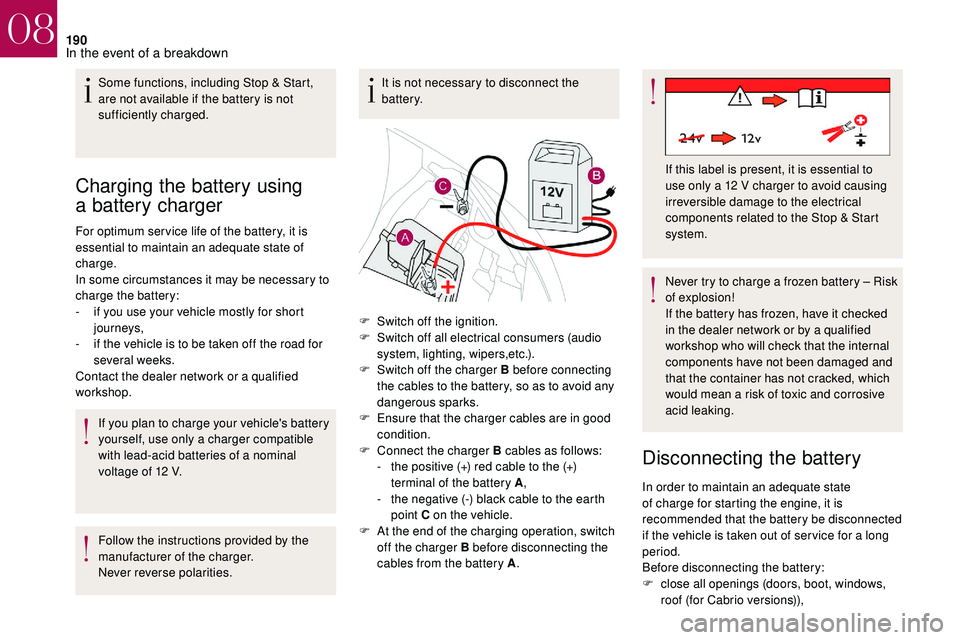
F
C
onnect the charger B cables as follows:
-
t
he positive (+) red cable to the (+)
terminal of the battery A ,
-
t
he negative (-) black cable to the earth
point C on the vehicle.
F
A
t the end of the charging operation, switch
off the charger B before disconnecting the
cables from the battery A . If this label is present, it is essential to
use only a
12 V charger to avoid causing
irreversible damage to the electrical
components related to the Stop & Start
system.
In order to maintain an adequate state
of charge for starting the engine, it is
recommended that the battery be disconnected
if the vehicle is taken out of ser vice for a
long
period.
Before disconnecting the battery:
F
c
lose all openings (doors, boot, windows,
roof (for Cabrio versions)),
08
In the event of a breakdown
Page 193 of 248
191
F switch off all electrical consumers (audio system, wipers, lighting, etc.),
F
s
witch off the ignition and wait for four
minutes.
Upon accessing the battery, you only need to
disconnect the positive (+) terminal.
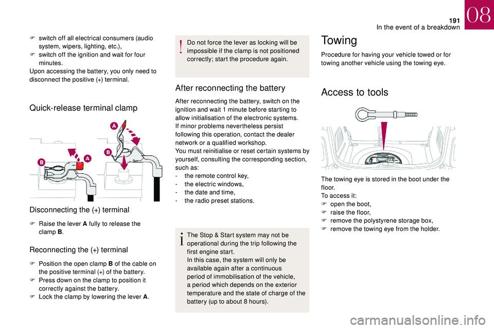
Quick-release terminal clamp
Disconnecting the (+) terminal
F Raise the lever A fully to release the clamp B .
Reconnecting the (+) terminal
F Position the open clamp B of the cable on
the positive terminal (+) of the battery.
F
P
ress down on the clamp to position it
correctly against the battery.
F
L
ock the clamp by lowering the lever A .Do not force the lever as locking will be
impossible if the clamp is not positioned
correctly; start the procedure again.
After reconnecting the battery
After reconnecting the battery, switch on the
ignition and wait 1
minute before starting to
allow initialisation of the electronic systems.
If minor problems nevertheless persist
following this operation, contact the dealer
network or a
qualified workshop.
You must reinitialise or reset certain systems by
yourself, consulting the corresponding section,
such as:
-
t
he remote control key,
-
t
he electric windows,
-
t
he date and time,
-
t
he radio preset stations.The Stop & Start system may not be
operational during the trip following the
first engine start.
In this case, the system will only be
available again after a
continuous
period of immobilisation of the vehicle,
a period which depends on the exterior
temperature and the state of charge of the
battery (up to about 8
hours).
To w i n g
Procedure for having your vehicle towed or for
towing another vehicle using the towing eye.
Access to tools
The towing eye is stored in the boot under the
f l o o r.
To access it:
F
o
pen the boot,
F
r
aise the floor,
F
r
emove the polystyrene storage box,
F
r
emove the towing eye from the holder.
08
In the event of a breakdown
Page 196 of 248
194
Characteristics of engines
and towed loads
Engines
The engine specifications (capacity, max.
power, max. speed, energy, CO
2 emissions,
e
tc.) for your vehicle are given in the
registration document and in the sales
literature.
These characteristics correspond to the values
type-approved on a
test bed, under conditions
defined in European legislation
(Directive 1999/99/EC).
For more information, contact the dealer
network or a
qualified workshop.
Weights and towed loads
The maximum weights and towed loads for
your vehicle are given in the registration
document and in the sales literature.
These values are also given on the
manufacturer's plate or label.
For more information, contact the dealer
network or a qualified workshop. The GTW and towed load values indicated are
valid up to a
maximum altitude of 1,000 metres.
The towed load value must be reduced by 10%
for each additional 1,000 metres of altitude.
The maximum authorised nose weight
corresponds to the weight permitted on the
towbar (removable with or without a tool).
GT W: Gross train weight.
High exterior temperatures may result
in a reduction in the per formance of
the vehicle to protect the engine. If the
exterior temperature is above 37°C, limit
the towed load.
Towing with a
towing vehicle which is only
slightly laden may negatively affect its
handling.
Towing a
trailer increases the braking
distance.
When towing, never exceed the speed
of 62
mph (100 km/h) (obser ve the local
legislation in force). If the exterior temperature is high, it is
recommended that the engine be allowed
to idle for 1
to 2 minutes after the vehicle
comes to a stop, to facilitate its cooling.
09
Technical data