CITROEN RELAY 2016 Handbook (in English)
Manufacturer: CITROEN, Model Year: 2016, Model line: RELAY, Model: CITROEN RELAY 2016Pages: 308, PDF Size: 10.98 MB
Page 261 of 308

259
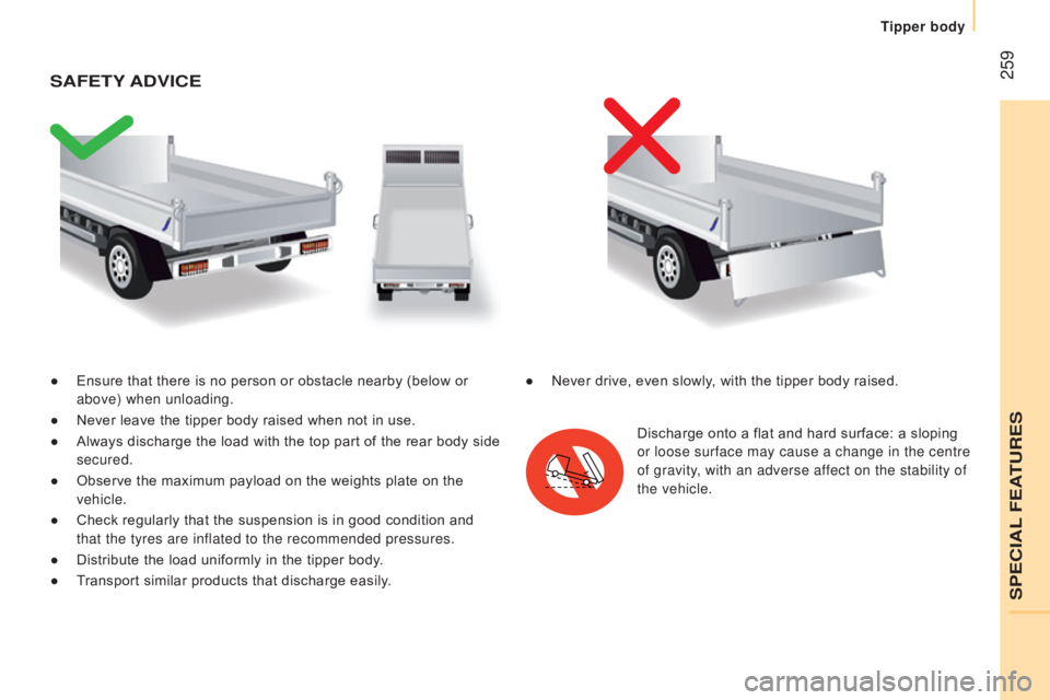
● Ensure that there is no person or obstacle nearby (below or
above) when unloading.
●
Never leave the tipper body raised when not in use.
●
Always discharge the load with the top part of the rear body si
de
secured.
●
Observe the maximum payload on the weights plate on the
vehicle.
●
Check regularly that the suspension is in good condition and
that the tyres are inflated to the recommended pressures.
●
Distribute the load uniformly in the tipper body
.
●
T
ransport similar products that discharge easily.
SAFEtY A d VI c E
Discharge onto a flat and hard surface: a sloping
or loose surface may cause a change in the centre
of gravity, with an adverse affect on the stability of
the vehicle.
●
Never drive, even slowly
, with the tipper body raised.
SPECIAL FEATURES
Tipper body
Page 262 of 308

260
cHArActErIStIcS
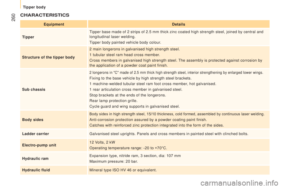
Equipmentdetails
tipperT
ipper base made of 2 strips of 2.5 mm thick zinc coated high strength st\
eel, joined by central and
longitudinal laser welding.
Tipper body painted vehicle body colour.
Structure of the tipper body 2 main longerons in galvanised high strength steel.
1 tubular steel ram head cross member.
Cross members in galvanised high strength steel. The assembly is protected against corrosion by
the application of a powder coat paint finish.
Sub chassis
2 longerons in "C" made of 2.5 mm thick high strength steel, interior st\
rengthening by enlarged lower wings.
Fixing to the base vehicle by high strength steel brackets.
1 machine-welded tubular steel ram foot cross member, hot galvanised.
1 rear articulation cross member in galvanised steel.
Stop brackets at the ends of the longerons.
Rear lamp protection grille.
Cycle guard and wing supports in galvanised steel.
Body sides
Body sides in high strength steel, 15/10 thickness, cold formed, assembled by continuous laser welding.
Anti-corrosion protection assured by a powder coating paint finish.
Catches with reinforced zinc protection integrated into the form of the \
sides.
Ladder carrier Galvanised steel uprights. Panels and cross members in painted steel wit\
h clinched bolts.
Electro-pump unit 12 Volts, 2 kW
Operating temperature range: -20 to +70°C.
Hydraulic ram Expansion type, nitride ram, 3 section, dia: 107 mm
Maximum pressure: 20 bar.
Hydraulic fluid Mineral type ISO HV 46 or equivalent.
Tipper body
Page 263 of 308

261
tipper (in mm)
Load length 3 200
Overall length 3
248
Load width 2 000
Overall width 2 100
Height of body sides 350
Overall height 550
dIMEnSIOnS
This conversion is only available on the L2 single chassis-cab; refer to\
the table below for the characteristics of the tipper.
For information on the characteristics of the L2 chassis cab, refer to t\
he "Dimensions" section for the floor cab version.
SPECIAL FEATURES
Tipper body
Page 264 of 308

262
WEIGHtS And tOWE d LOA d S ( KG )
For more information, refer to your registration certificate.
In each country, it is imperative that the towed loads authorised by
local legislation are complied with. To find out your vehicle's towing
capacities and its gross train weight, consult a franchised dealer.
The maximum authorised speed is reduced when towing (comply
with the legislation in force in your country).
With load transfer, the braked trailer weight can be increased,
on condition that the equivalent of this load is removed from the
vehicle so that the GTW is not exceeded. Warning: towing with a
lightly loaded towing vehicle may have an adverse effect on its road
holding.
The GTW and towed load values indicated are valid up to a
maximum altitude of 1000 metres; the towed load mentioned must
be reduced by 10 % for each additional 1000 metres.
High ambient temperatures may result in a reduction in the
performance of the vehicle in order to protect the engine; when the
ambient temperature is higher than 37 °C, limit the towed weight.
The kerb weight is equal to the weight without load + driver (75
kg) +
fuel tank filled to 90%. Before towing a trailer, check
that:
-
the nose weight on the
towbar ball does not exceed
the value (S) indicated on
the trailer's weights plate,
-
the maximum trailer weight
is less than the value
indicated on the trailer's
weights plate and the Gross
Vehicle Weight (GVW)
does not exceed the value
indicated on the vehicle's
weights plate.
-
in the case of a self-
supporting trailer
, the Gross
Train Weight must not
exceed the value indicated
on the vehicle's weights
plate.
General points
Tipper body
Page 265 of 308

263
HYdrAuLIc SYStEM
these precautions are mandatory for any work on the hydraulic
system.
●
When carrying out maintenance work under the tipper body
,
place the tipper body in the safety position secured with its stay
(position indicated by a red arrow under the back of the tipper
body),
●
Never work under a tipper body that is not supported,
●
Switch of
f the power supply to the electro-hydraulic unit using
the circuit breaker,
●
V
ehicle stationary, engine off.
As a safety measure we strongly advise against doing anything
under the tipper body while it is being operated or while it is
being serviced.
SPECIAL FEATURES
Tipper body
Page 266 of 308

264
SErVIc I n G
r eservoir
Check and top up the fluid level regularly. Replace the fluid
annually. Replace the fluid if it contains water.
Check the condition of the hydraulic hose and the sealing of the
hydraulic system regularly.
Pump and motor
Requires no servicing, the ball bearings are lubricated for life and
the plain bearings by the pumped fluid.
Lubrication
The tipper body and ram pivots do not have grease nipples.
Lubricate regularly the hinges and retainers for the tipper body sides
as well as the catches for the rear tipper body side.
Sub-chassis and tipper body
For maximum life, we recommend that you clean your tipper body
by washing it down regularly with hose.
Touch-in the paint chips quickly to avoid the spread of rust.
After 8 months of use, check the tightening torque of the
fixings of the underbody to the chassis (following the
recommendations of the body converter).
cleaning the valve slider
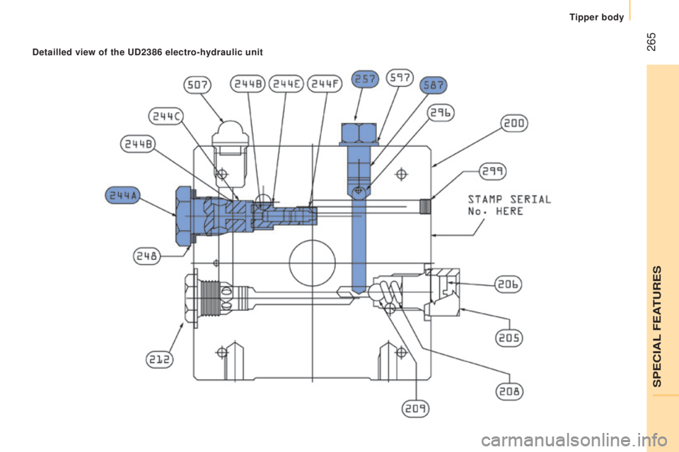
● Remove the plug 244A taking care to recover the ball.
●
Using a wide screwdriver
, remove the bore / piston bolt
assembly.
●
Check that the piston slides smoothly and remove any
impurities. Pass a magnet over if there is any swarf present.
●
Refit the assembly and ensure that the piston slides smoothly
.
Retain the ball with some grease on the plug for reassembly.
●
Bleed the hydraulic system.
Bleed the electro-hydraulic unit
● Remove the hexagonal plug 257.
●
Slacken by a half turn the bolt
587 located inside, using a
hexagonal 6 mm spanner.
●
Operate the electro-hydraulic unit for a few moments by
pressing the raise button.
●
The tipper body does not rise, or very slowly
. When fluid flows
from the orifice, the system is bled.
●
Retighten bolt
587 and refit the plug 257, check that the tipper
body lowers correctly.
Tipper body
Page 267 of 308

265detailled view of the ud2386 electro-hydraulic unit
SPECIAL FEATURES
Tipper body
Page 268 of 308

266
dIAGnOSIS
SymptomElectricalHydraulic Verification / c heck
The hydraulic unit does
not operate. X
Power supply harness and relay.
X Control harness (control unit).
X Circuit breaker.
Unit very noisy, body
rises slowly. X
Pick-up strainer blocked or squashed at the bottom of the reservoir.
New unit very noisy,
body rises quickly. X
Pump alignment, change the unit.
The ram goes down on
its own. X
Return valve squashed or jammed.
The ram does not go
down. X
Yes, check the valve slider and bleed.
Refer to the "Servicing" section.
X No, check the return valve winding and electrical connections.
X No, replace the electrovalve.
X No, check the alignment of the ram.
Tipper body
Page 269 of 308

267
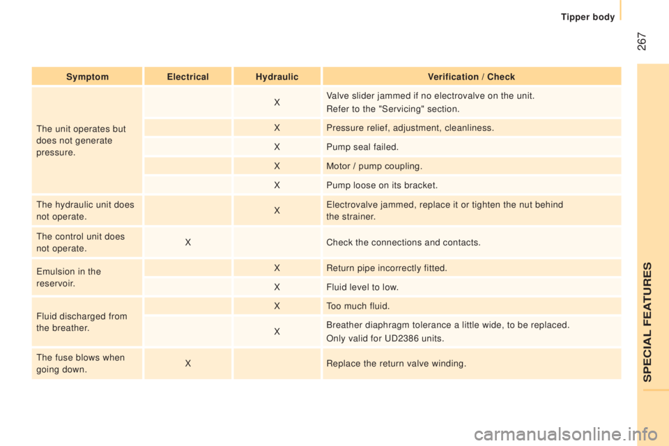
SymptomElectricalHydraulic Verification / c heck
The unit operates but
does not generate
pressure. X
Valve slider jammed if no electrovalve on the unit.
Refer to the "Servicing" section.
X Pressure relief, adjustment, cleanliness.
X Pump seal failed.
X Motor / pump coupling.
X Pump loose on its bracket.
The hydraulic unit does
not operate. XElectrovalve jammed, replace it or tighten the nut behind
the strainer.
The control unit does
not operate. X
Check the connections and contacts.
Emulsion in the
reservoir. X
Return pipe incorrectly fitted.
X Fluid level to low.
Fluid discharged from
the breather. X
Too much fluid.
X Breather diaphragm tolerance a little wide, to be replaced.
Only valid for UD2386 units.
The fuse blows when
going down. X
Replace the return valve winding.
SPECIAL FEATURES
Tipper body
Page 270 of 308
