charging DATSUN 210 1979 Service Manual
[x] Cancel search | Manufacturer: DATSUN, Model Year: 1979, Model line: 210, Model: DATSUN 210 1979Pages: 548, PDF Size: 28.66 MB
Page 136 of 548
3
Check
air
injection
pump
belt
tension
and
adjust
to
specifications
if
necessary
4
Plug
up
air
discharging
hose
from
C
A
C
valve
California
models
y
o
EC144A
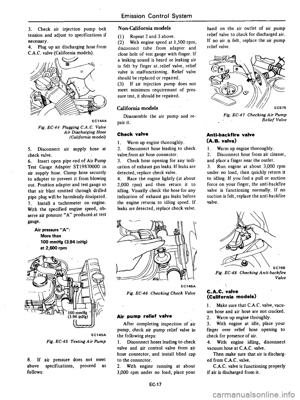
Fig
EC
44
Plugging
C
A
C
Value
Air
Discharging
Hose
California
model
S
Disconnect
air
supply
hose
at
check
valve
6
Insert
open
pipe
end
of
Air
Pump
Test
Gauge
Adapter
STl9870000
in
air
supply
hose
Clamp
hose
securely
to
adapter
to
prevent
it
from
blowing
out
Position
adapter
and
test
gauge
so
that
air
blast
emitted
through
drilled
pipe
plug
will
be
harmlessly
dissipated
7
Install
a
tachometer
on
engine
With
the
specified
engine
speed
ob
serye
air
pressure
A
produced
at
test
gauge
Air
pressure
A
More
than
100
mmHg
3
94
inHg
at
2
600
rpm
I
jff
100
m
Hg
f1
3
94
mHg
I
EC145A
Fig
EC
45
Testing
Air
Pump
8
If
air
pressure
does
not
meet
above
specifications
proceed
as
follows
Emission
Control
System
Non
California
models
1
Repeat
2
and
3
above
2
With
engine
speed
at
1
500
rpm
disconnect
tube
from
adapter
and
close
hole
of
test
gauge
with
finger
If
a
leaking
sound
is
heard
or
leaking
air
is
felt
by
finger
at
relief
valve
relief
valve
is
malfunctioning
Relief
valve
should
be
replaced
or
repaired
3
If
air
injection
pump
does
not
meet
minimum
requirement
of
pres
sure
test
it
should
be
repaired
California
models
Disassemble
the
air
pump
and
re
pair
it
Check
valve
Warm
up
engine
thoroughiy
2
Disconnect
hose
leading
to
check
valve
from
air
hose
connector
3
Check
hose
opening
for
any
indi
cation
of
exhaust
gas
leaks
If
leaks
are
detected
replace
check
valve
4
Race
the
engine
lightly
at
about
2
000
rpm
and
then
return
it
to
idling
Visually
check
the
hose
for
any
indication
of
exhaust
gas
leaks
before
the
engine
returns
to
idling
speed
If
leaks
are
detected
replace
check
valve
EC146A
Fig
EC
46
Checking
Check
Valve
Air
pump
relief
valve
After
completing
inspection
of
air
pump
check
air
pump
relief
valve
in
the
following
steps
I
Disconnect
hoses
leading
to
check
valve
and
air
control
valve
from
air
hose
connector
and
install
blind
c
p
to
the
connector
2
With
engine
running
at
about
3
000
rpm
under
no
load
place
your
EG
7
hand
on
the
air
outlet
of
air
pump
relief
valve
to
check
for
discharged
air
If
no
air
is
felt
replace
the
air
pump
relief
valve
G
EC575
Fig
EC
47
Checking
Air
Pump
Relief
Valve
Anti
backfire
valve
A
B
valve
I
Warm
up
engine
thoroughly
2
Disconnect
hose
from
air
cleaner
and
place
a
finger
near
the
outlet
3
Run
engine
at
about
3
QOO
rpm
under
no
load
then
quickly
return
it
to
idling
If
you
feel
a
pull
or
suction
force
on
your
finger
the
anti
backfire
valve
is
functioning
normally
If
no
suction
is
felt
replace
the
anti
backfire
valve
EC768
Fig
EC
48
Chocking
Anti
backfire
Valve
C
A
C
valve
California
models
I
Make
sure
that
C
A
C
valve
vacu
um
hose
and
air
hose
are
not
cracked
2
Warm
up
engine
throughly
3
With
engine
at
idle
place
your
fmger
over
relief
hose
opening
to
check
for
presence
of
air
4
With
engine
idling
disconnect
vacuum
hose
at
C
A
C
valve
Then
make
sure
that
air
is
discharg
ed
from
C
A
C
valve
C
A
C
valve
is
functioning
properly
if
air
is
discharged
from
it
Page 159 of 548
DATSUN
210
Model
8310
Series
SECTIONEE
ENGINE
ELECTRICAL
SYSTEM
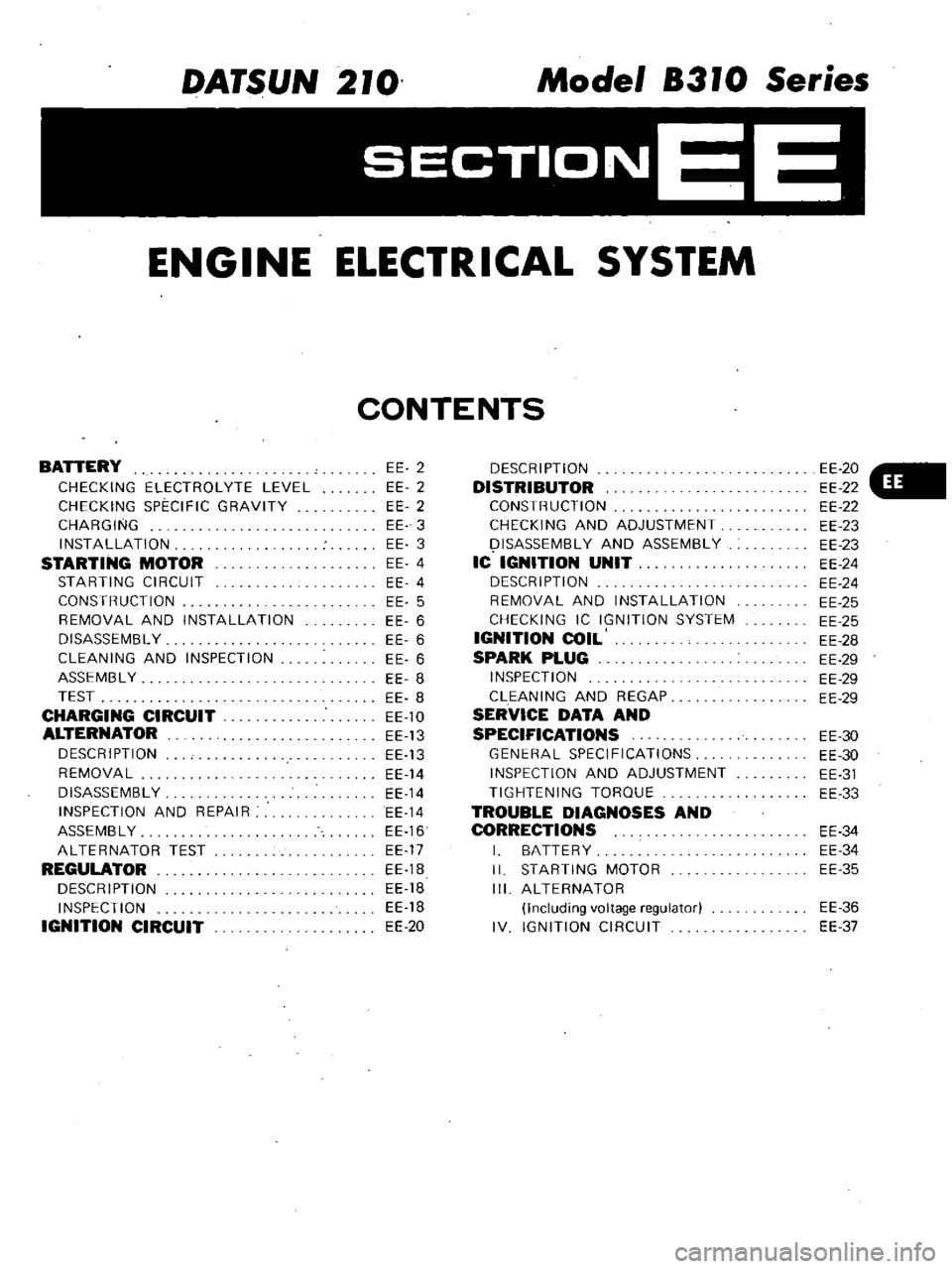
CONTENTS
BATTERY
CHECKING
ELECTROLYTE
LEVEL
CHECKING
SPECIFIC
GRAVITY
CHARGING
INSTALLATION
STARTING
MOTOR
STARTING
CIRCUIT
CONSTRUCTION
REMOVAL
AND
INSTALLATION
DISASSEMBL
Y
CLEANING
AND
INSPECTION
ASSEMBL
Y
TEST
CHARGING
CIRCUIT
ALTERNATOR
DESCRIPTION
REMOVAL
DISASSEMBLY
INSPECTION
AND
REPAIR
ASSEMBLY
ALTERNATOR
TEST
REGULATOR
DESCRIPTION
INSPECTION
IGNITION
CIRCUIT
EE
2
EE
2
EE
2
EE
3
EE
3
EE
4
EE
4
EE
5
EE
6
EE
6
EE
6
EE
8
EE
8
EE
10
EE
13
EE
13
EE
14
EE
14
EE
14
EE
16
EE
17
EE
1B
EE
18
EE
18
EE
20
DESCRIPTION
DISTRIBUTOR
CONSTRUCTION
CHECKING
AND
ADJUSTMENT
I
ISASSEMBL
Y
AND
ASSEMBLY
IC
IGNITION
UNIT
DESCRIPTION
REMOVAL
AND
INSTALLATION
CHECKING
IC
IGNITION
SYSTEM
IGNITION
COIL
SPARK
PLUG
INSPECTION
CLEANING
AND
REGAP
SERVICE
DATA
AND
SPECIFICATIONS
GENERAL
SPECIFICATIONS
INSPECTION
AND
ADJUSTMENT
TIGHTENING
TORQUE
TROUBLE
DIAGNOSES
AND
CORRECTIONS
I
BATTERY
II
STARTING
MOTOR
III
ALTERNATOR
Including
voltage
regulator
IV
IGNITION
CIRCUIT
EE
20
EE
22
EE
22
EE
23
EE
23
EE
24
EE
24
EE
25
EE
25
EE
28
EE
29
EE
29
EE
29
EE
30
EE
30
EE
31
EE
33
EE
34
EE
34
EE
35
EE
36
EE
37
Page 160 of 548
WARNING
Never
touch
positive
and
negative
terminals
at
the
same
time
with
are
hands
Th
l
Il
d
result
in
injury
CHECKING
ELECTROLYTE
LEVEL
Remove
six
vent
plugs
and
check
for
electrolyte
level
in
each
cell
If
necessary
pour
distilled
water
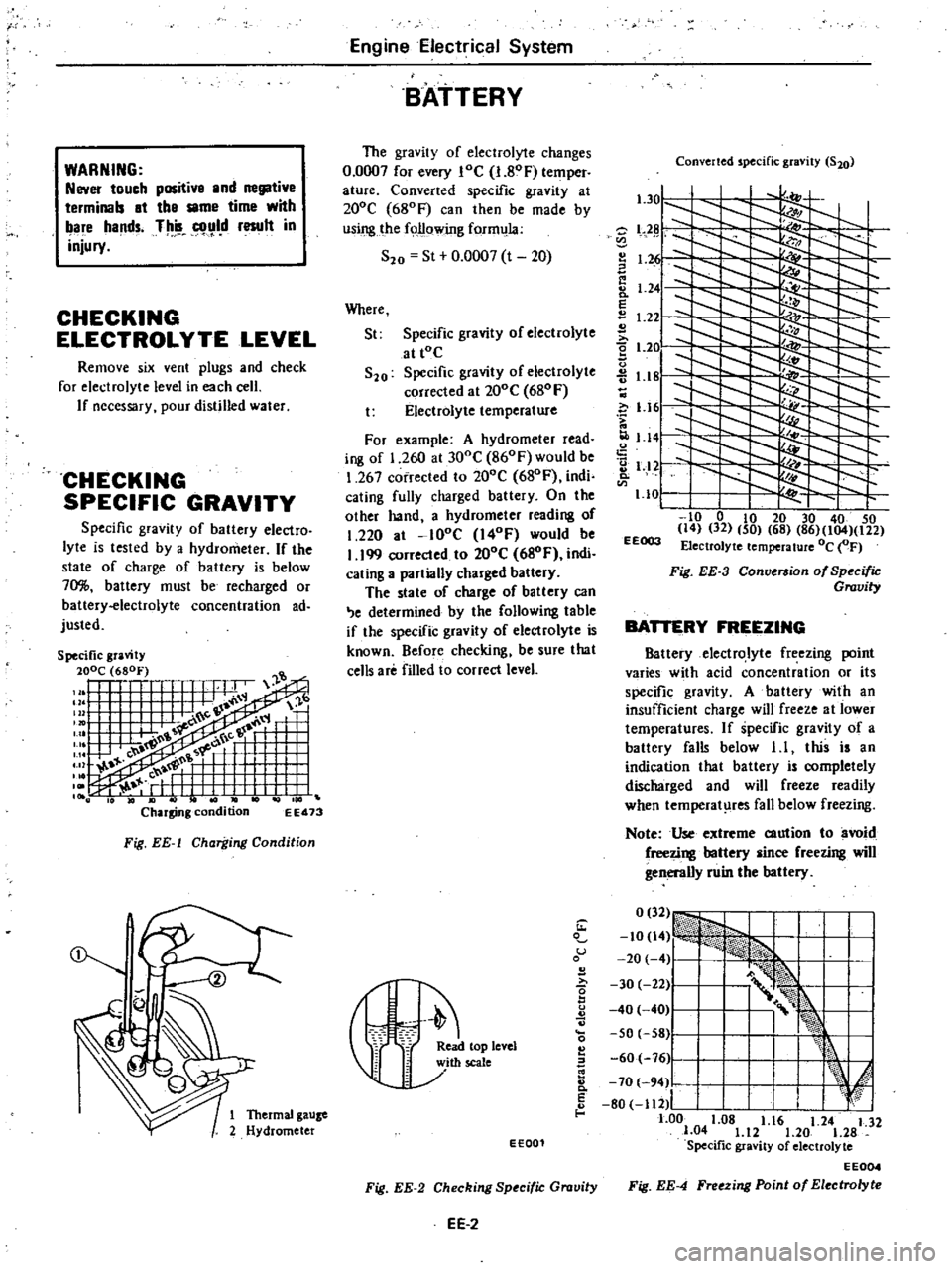
CHECKING
SPECIFIC
GRAVITY
Specific
gravity
of
battery
electro
lyte
is
tested
by
a
hydrometer
If
the
state
of
charge
of
battery
is
below
70
battery
must
be
recharged
or
battery
electrolyte
concentration
ad
justed
EE473
Fig
EE
l
Charging
Condition
Engine
Electrical
System
BATTERY
The
gravity
of
electrolyte
changes
0
0007
for
every
loe
I
80F
temper
ature
Converted
specific
gravity
at
200e
680F
can
then
be
made
by
using
the
following
form
la
S20
St
0
0007
t
20
Where
St
Specific
gravity
of
electrolyte
at
tOe
S20
Specific
gravity
of
electrolyte
corrected
al
200e
680
F
t
Electrolyte
temperature
For
example
A
hydrometer
read
ing
of
1
260
at
300e
860F
would
be
1
267
corrected
to
200e
680F
indi
cating
fully
charged
battery
On
the
olher
hand
a
hydrometer
reading
of
1
220
at
lOoe
I40F
would
be
I
199
corrected
to
200e
680F
indi
cating
a
partially
charged
battery
The
state
of
charge
of
battery
can
e
determined
by
the
following
table
if
the
specific
gravity
of
electrolyte
is
known
Before
checking
be
sure
that
cells
are
filled
to
correct
level
Converted
specific
gravity
S20
l
301
l
Z
L2
I
1
2
I
Ii
8
1
24
E
1
22
2
t
2e
u
1
18
c
i
1
161
1
141
2
1
12
Q
1
10
I
to
0
to
20
30
40
50
14
32
50
68
86
104
122
EEOO3
Electrolyte
temperature
Oc
OF
Fig
EE
3
Conversion
of
Specific
Gravity
BATTERY
FREEZING
Battery
electrolyte
freezing
point
varies
with
acid
concentration
or
its
specific
gravity
A
battery
with
an
insufficient
charge
will
freeze
al
lower
temperatures
If
specific
gravity
of
a
battery
falls
below
1
I
this
is
an
indication
that
battery
is
completely
discharged
and
will
freeze
readily
when
temperat
res
fall
below
freezing
Note
Use
extreme
caution
to
avoid
freezing
battery
since
freezing
will
generally
ruin
the
battery
1
u
B
I
r
eleYel
60
76
Ji
I
k
E
I
I
d
8
70
94
80
112
I
I
f
1
Thermal
gauze
1
00
1
08
1
16
1
24
1
32
2
Hydrometer
1
04
1
12
1
20
1
28
EE001
Specific
gravity
of
electrolyte
EE004
Fig
EE
2
Checking
Specific
Gravity
Fig
EE
4
Freezing
Point
of
Electrolyte
EE
2
Page 161 of 548
CHARGING
If
electrolyte
level
is
satisfactory
battery
must
be
charged
when
electro
lyte
gravity
reading
falls
below
1
20
or
1
22
NS70
If
battery
on
car
is
quick
charged
to
bring
it
up
to
full
charge
the
operation
should
be
carried
out
with
negative
cable
removed
Prior
to
charging
corroded
termi
nals
should
be
cleaned
with
a
brush
and
common
baking
soda
solution
In
addition
the
following
items
should
be
observed
while
battery
is
being
Engine
Electrical
System
charged
I
Be
sure
that
electrolyte
level
is
above
top
of
each
plate
2
Keep
removed
plugs
in
a
safe
place
3
Do
not
allow
electrolyte
tempera
ture
to
go
over
4SoC
1130F
4
After
charging
check
to
be
cer
tain
that
specific
gravity
does
not
exceed
maximum
charging
specific
gravity
at
20
C
680F
Correction
can
be
made
by
adding
distilled
water
into
cells
as
necessary
5
Keep
battery
away
from
open
EE
3
flame
while
it
is
being
charged
6
After
all
vent
plugs
have
been
tightened
clean
all
sprayed
electrolyte
off
upper
face
of
battery
INSTALLATION
1
InstaU
and
tighten
clamps
secure
ly
2
After
clamps
have
been
tightened
clean
battery
cable
terminals
and
apply
grease
to
retard
formation
of
corrosion
Page 168 of 548
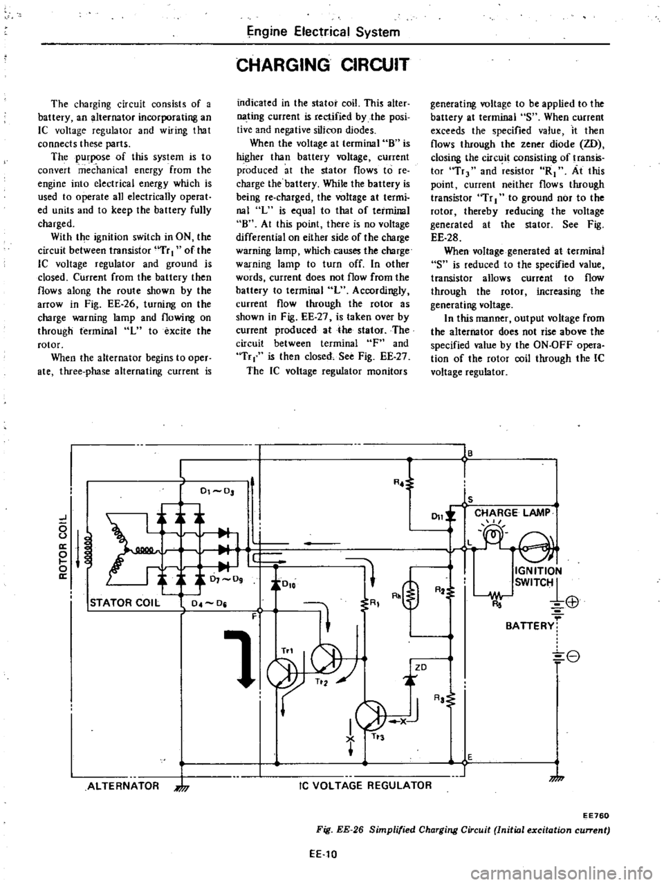
The
charging
circuit
consists
of
a
battery
an
alternator
incorporating
an
IC
voltage
regulator
and
wiring
that
connects
these
parts
The
purpose
of
this
system
is
to
convert
mec
hanka
energy
from
the
engine
into
electrical
energy
which
is
used
to
operate
all
electrically
operat
ed
units
and
to
keep
the
battery
fully
charged
With
the
ignition
switch
in
ON
the
circuit
between
transistor
uTr
I
of
the
lC
voltage
regulator
and
ground
is
closed
Current
from
the
battery
then
flows
along
the
route
shown
by
the
arrOW
in
Fig
EE
26
turning
on
the
charge
warning
lamp
and
flowing
on
through
terminal
L
to
excite
the
rotor
When
the
alternator
begins
to
oper
ate
three
phase
alternating
current
is
ngine
Elect
ical
System
CHARGING
CIRCUIT
indicated
in
the
stator
coil
This
alter
nating
current
is
rectified
by
the
posi
tive
and
negative
silicon
diodes
When
the
voltage
at
terminal
8
is
higher
than
battery
voltage
current
produced
at
the
stator
flows
to
re
charge
the
battery
While
the
battery
is
being
re
charged
the
voltage
at
termi
nal
L
is
equal
to
that
of
terminal
8
At
this
point
there
is
no
voltage
differential
on
either
side
of
the
charge
warning
lamp
which
causes
the
charge
warning
lamp
to
turn
off
In
other
words
current
does
not
flow
from
the
battery
to
terminal
L
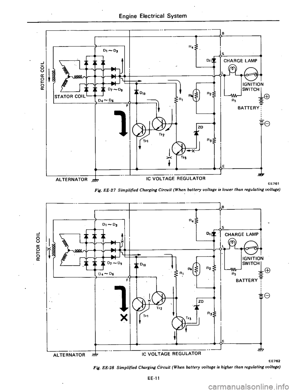
Accordingly
current
flow
through
the
rotor
as
shown
in
Fig
EE
27
is
taken
over
by
current
produced
at
the
stator
The
circuit
between
terminal
F
and
Tr
is
then
closed
See
Fig
EE
27
The
IC
voltage
regulator
monitors
generating
voltage
to
be
applied
to
the
battery
at
terminal
S
When
current
exceeds
the
specified
value
it
then
flows
through
the
zener
diode
ZD
closing
the
circ
it
consisting
of
transis
tor
Tr
and
resistor
R1
At
this
point
current
neither
flows
through
transistor
Tr
I
to
ground
nor
to
the
rotor
thereby
reducing
the
voltage
generated
at
the
stator
See
Fig
EE
28
When
voltage
generated
at
terminal
S
is
reduced
to
the
specified
value
transistor
allows
current
to
flow
through
the
rotor
increasing
the
generating
voltage
In
this
manner
output
voltage
from
the
alternator
does
not
rise
above
the
specified
value
by
the
ON
OFF
opera
tion
of
the
rotor
coil
through
the
IC
voltage
regulator
16
L
R
l
I
01
0
ls
CHARGE
LAMP
J
011
L
e
0
u
a
M
e
i
J
0
io
o
IGNITION
a
0
09
SWITC1
R2
El1
STATOR
COIL
04
0
R
F
1
BATTERY
8
ZD
ALTERNATOR
7
I
1
AJ
TI
3
IC
VOLTAGE
REGULATOR
Aa
E
1
7
EE760
Fig
EE
26
Simplified
Charging
Circuit
Initial
excitation
current
EE
10
Page 169 of 548
J
o
u
o
ll
ALTERNATOR
nJn
l
0
0
Engine
Electrical
System
F
00IB
RJ
1
1s
0111
CHARGE
LAMP
rt
ei
tOlD
11
1
IGNITION
SWITC1
R2
i
I
oJor
EB
R
BATTERY
f
3
07
09
0
4
0
1
8
r
I
G
XiJ
Tts
R
o
s
o
E
1
J
IC
VOLTAGE
REGULATOR
Fig
EE
27
Simplified
Charging
Circ14it
When
battery
voltage
is
lower
than
regulating
voltage
EE761
I
h
it
r
f
1
0
0
J
o
U
ll
o
I
o
cr
ALTERNATOR
m
l
01
03
1
X
RJ
16
I
1s
OIlI
r
CHARGE
LAMP
L
l
@
R2
IGNITION
SWITCH1
w
Lp
R
l
Q7
BATTERY
T
8
T
F
i
R
j
JZO
RS
E
J
7
Ie
VOLTAGE
REGULATOR
EE762
Fig
EE
28
Simplified
Cluzrging
Circuit
When
battery
voltage
i
higher
than
regulating
voltage
EE
11
Page 171 of 548
DESCRIPTION
The
alternator
incorporates
an
Ie
voltage
regulator
which
maintains
volt
age
within
the
specified
range
and
prevents
output
voltage
from
rising
higher
than
the
specified
value
Except
for
the
Ie
circuit
alternator
parts
are
essentially
the
same
as
those
of
the
conventional
type
alternator
Service
procedures
outlined
in
this
section
are
restricted
to
information
on
other
than
the
voltage
regulator
In
the
alternator
a
magnetic
field
is
CD
Engine
Electrical
System
ALTERNATOR
produced
by
the
rotor
which
consists
of
alternator
shaft
field
coil
pole
pieces
and
slip
rings
The
slip
rings
pressed
in
the
shaft
conduct
only
a
small
field
current
Output
current
is
generated
in
the
armature
coils
located
in
the
stator
The
stator
has
three
windings
and
generates
three
phase
alternating
current
Silicon
diodes
act
like
a
one
way
valve
for
electricity
so
that
charging
current
passes
easily
but
reverse
current
is
shut
out
In
this
alternator
pack
type
silicon
diodes
are
used
as
main
diodes
Nine
diodes
three
negative
three
positive
and
three
sub
diodes
are
installed
in
positive
and
negative
plates
as
an
assembly
These
diodes
are
direct
soldered
at
their
tips
and
constructed
with
posi
tive
and
negative
conjunction
They
are
mounted
on
the
two
plates
which
combine
the
function
of
heat
dissipating
plate
and
positive
negative
terminals
and
are
light
in
weight
and
easy
to
service
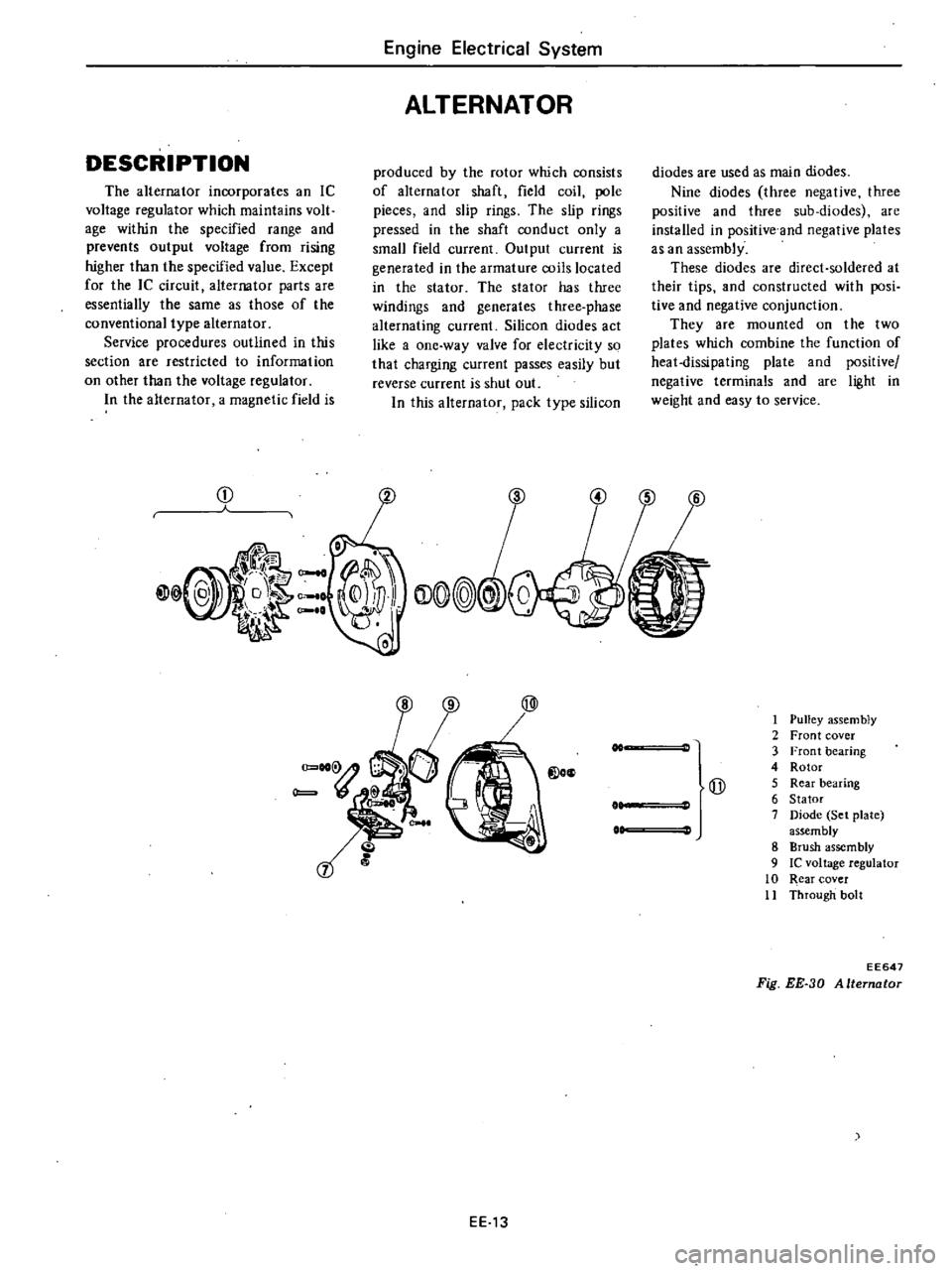
EE13
1
Pulley
assem
bly
2
Front
cover
3
Front
bearing
4
Rotor
Qj
5
Rear
bearing
6
Stator
7
Diode
Set
plate
assembly
8
Brush
assembly
9
Ie
voltage
regulator
10
Rear
cover
11
Through
bolt
EE647
Fig
EE
30
Alternator
Page 176 of 548
DESCRIPTION
The
regulator
consists
essentially
of
in
egrated
circuits
incorporating
tran
sistors
These
transistors
int
errupt
and
admit
current
flow
to
the
alternator
rotor
coil
thus
maintaining
its
output
voltage
at
a
constant
value
Unlike
in
a
mechanical
type
regulator
an
electron
ic
relay
employing
transistors
is
uti
lized
These
transistors
are
enclosed
in
a
very
compact
sealed
case
The
electronic
relay
is
soldered
to
the
Brush
Ie
regulator
R
J
DIO
F
i
ZD
Tn
Engipe
Electrjcal
Syst
em
REGULATOR
brush
assembly
inside
the
alternator
Should
any
problem
with
the
relay
arise
it
should
be
replaced
together
with
the
brush
assembly
In
the
charge
warning
lamp
circuit
a
diode
is
at
tached
to
the
stator
coil
to
monitor
generating
voltage
at
the
stator
so
that
when
the
monitored
voltage
and
charging
voltage
are
equal
during
re
charging
the
charge
warning
lamp
is
turned
off
Accordingly
a
charge
warning
relay
is
not
employed
in
this
circuit
s
r
t
E
F
L
S
B
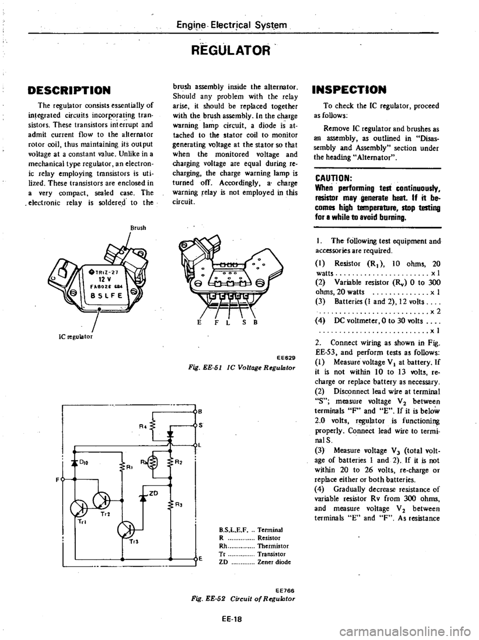
EE629
Fig
EE
51
lC
Voltage
RegultJtor
I
B
S
L
I
R
R
E
B
S
L
E
F
Terminal
R
Resistor
Rh
Thermistor
Tr
Transistor
ZD
Zener
diode
EE766
Fig
EE
52
Circuit
of
RegultJtor
EE
18
INSPECTION
To
check
the
IC
regulator
proceed
as
follows
Remove
IC
regulator
and
brushes
as
an
assembly
as
outlined
in
Disas
sembly
and
Assembly
section
under
the
heading
Alternator
CAUTION
When
performing
test
continuously
resistor
may
generate
heat
If
it
be
comes
high
temperature
stop
testing
for
a
while
to
avoid
burning
The
following
test
equipment
and
accessories
are
required
I
Resistor
R
10
ohms
20
watts
x
I
2
Variable
resistor
Rv
0
to
300
ohms
20
watts
x
I
3
Batteries
I
and
2
12
volts
x2
4
DC
voltmeter
0
to
30
volts
x
I
2
Connect
wiring
as
shown
in
Fig
EE
S3
and
perform
tests
as
follows
I
Measure
voltage
VI
at
battery
If
it
is
not
within
10
to
13
volts
re
charge
or
replace
battery
as
necessary
2
Disconnect
lead
wire
at
terminal
s
measure
voltage
V
2
between
terminals
F
and
E
If
it
is
below
2
0
volts
regulator
is
functioning
properly
Connect
lead
wire
to
termi
nalS
3
Measure
voltage
V
3
total
volt
age
of
batteries
I
and
2
If
it
is
not
within
20
to
26
volts
re
charge
or
replace
either
or
both
batteries
4
Gradually
decrease
resistance
of
variable
resistor
Rv
from
300
ohms
and
measure
voltage
V
2
between
terminals
En
and
F
As
resistance
Page 189 of 548
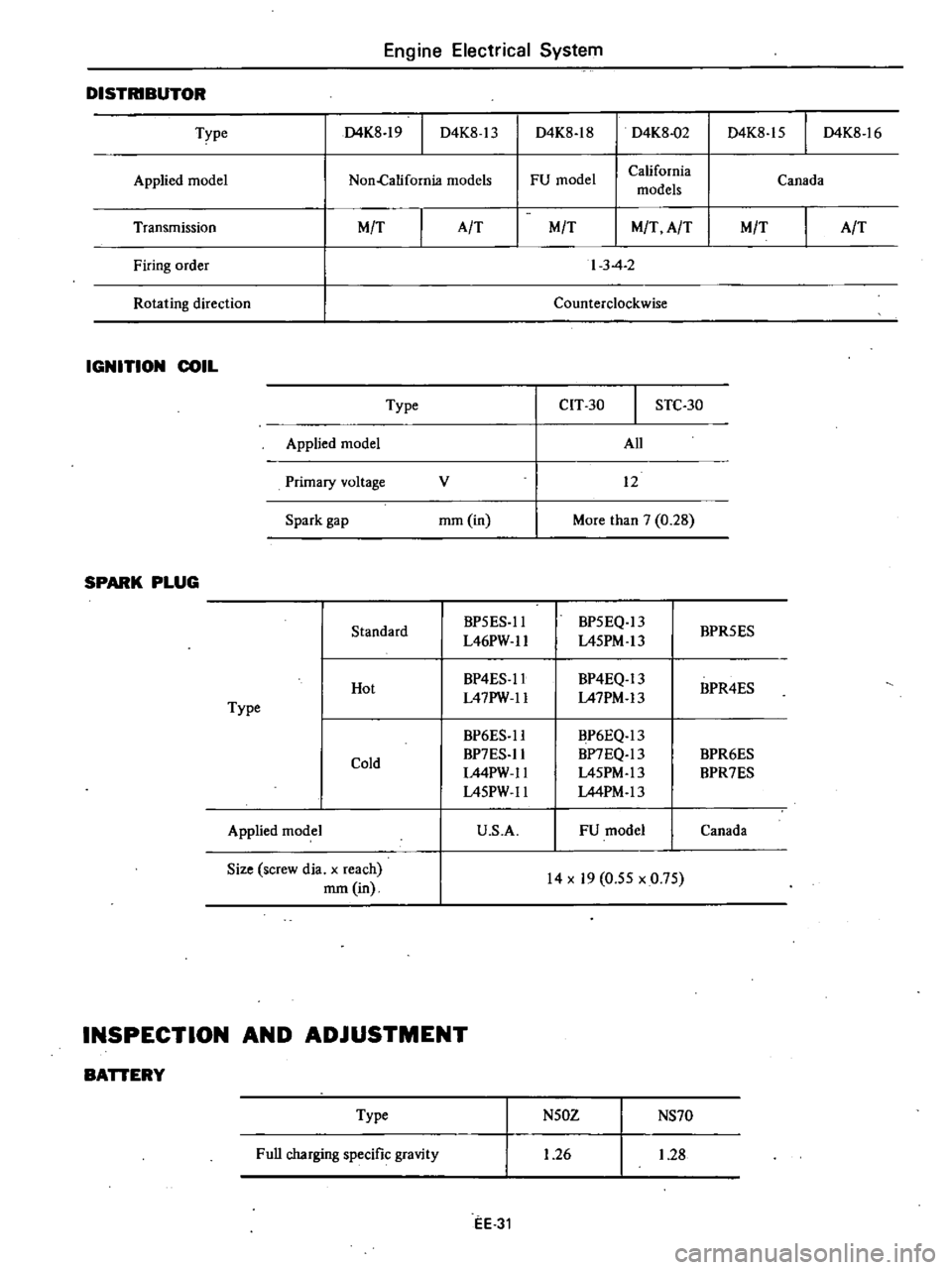
Engine
Electrical
System
DISTRIBUTOR
D4K8
18
D4K8
15
I
D4K8
16
Type
D4K8
19
I
D4K8
13
D4K8
02
Applied
model
FU
model
California
models
Canada
Non
California
models
Transmission
MfT
Firing
order
Rotating
direction
IGNITION
COIL
Type
Applied
model
Primary
voltage
Spark
gap
SPARK
PLUG
Standard
Hot
Type
Cold
Applied
model
Size
screw
dia
x
reach
mm
in
AfT
MfT
MfT
AfT
MfT
AfT
I
3
4
2
Counterclockwise
cn
30
STC
30
All
v
12
mm
in
More
than
7
0
28
BP5ES
II
BP5EQ
13
BPR5ES
L46PW
1I
L45PM
13
BP4ES
1I
BP4EQ
13
BPR4ES
L47PW
1I
L47PM
13
BP6ES
1I
BP6EQ
13
BP7ES
1I
BP7EQ
13
BPR6ES
L44PW
1I
L45PM
13
BPR7ES
L45PW
1I
L44PM
13
U
S
A
FU
model
Canada
14
x
19
0
55
x
0
75
INSPECTION
AND
ADJUSTMENT
BATTERY
Type
Full
charging
specific
gravity
N50Z
NS70
1
26
1
28
EE
31
Page 192 of 548
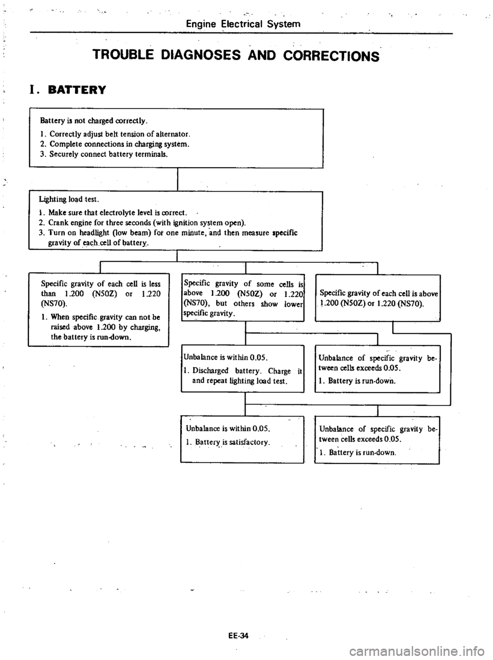
Engine
Electrical
System
TROUBLE
DIAGNOSES
AND
CORRECTIONS
I
BATTERY
Battery
is
not
charged
correctly
I
Correctly
adjust
belt
tension
of
alternator
2
Complete
connections
in
charging
system
3
Securely
connect
battery
terminals
Lighting
Joadtest
I
Make
sure
that
electrolyte
level
is
correct
2
Crank
engine
for
three
seconds
with
ignition
system
open
3
Turn
on
headlight
low
beam
for
one
minute
and
then
measure
specific
gravity
of
each
cell
of
battery
Specific
gravity
of
each
cell
is
less
than
1
200
N50Z
or
1
220
NS70
1
When
specific
gravity
can
not
be
raised
above
1
200
by
charging
the
battery
is
run
down
Specific
gravity
of
some
cells
is
above
1
200
N50Z
or
1
220
NS70
but
others
show
lower
specific
gravity
Unbalance
is
within
0
05
Discharged
battery
Charge
it
and
repeat
lighting
lood
test
Unbalance
is
within
0
05
Batter
is
satisfactory
EE
J4
Specific
gravity
of
each
cell
is
above
1
200
N50Z
or
1
220
NS70
Unbalance
of
specific
gravity
be
tween
cells
exceeds
0
05
I
Battery
is
run
down
Unbalance
of
specific
gravity
be
tween
cells
exceeds
0
05
I
Battery
is
run
down