engine oil DATSUN 210 1979 Owners Manual
[x] Cancel search | Manufacturer: DATSUN, Model Year: 1979, Model line: 210, Model: DATSUN 210 1979Pages: 548, PDF Size: 28.66 MB
Page 233 of 548
Manual
Transmission
S
R
o
o
D
l
@
@
l
@
l
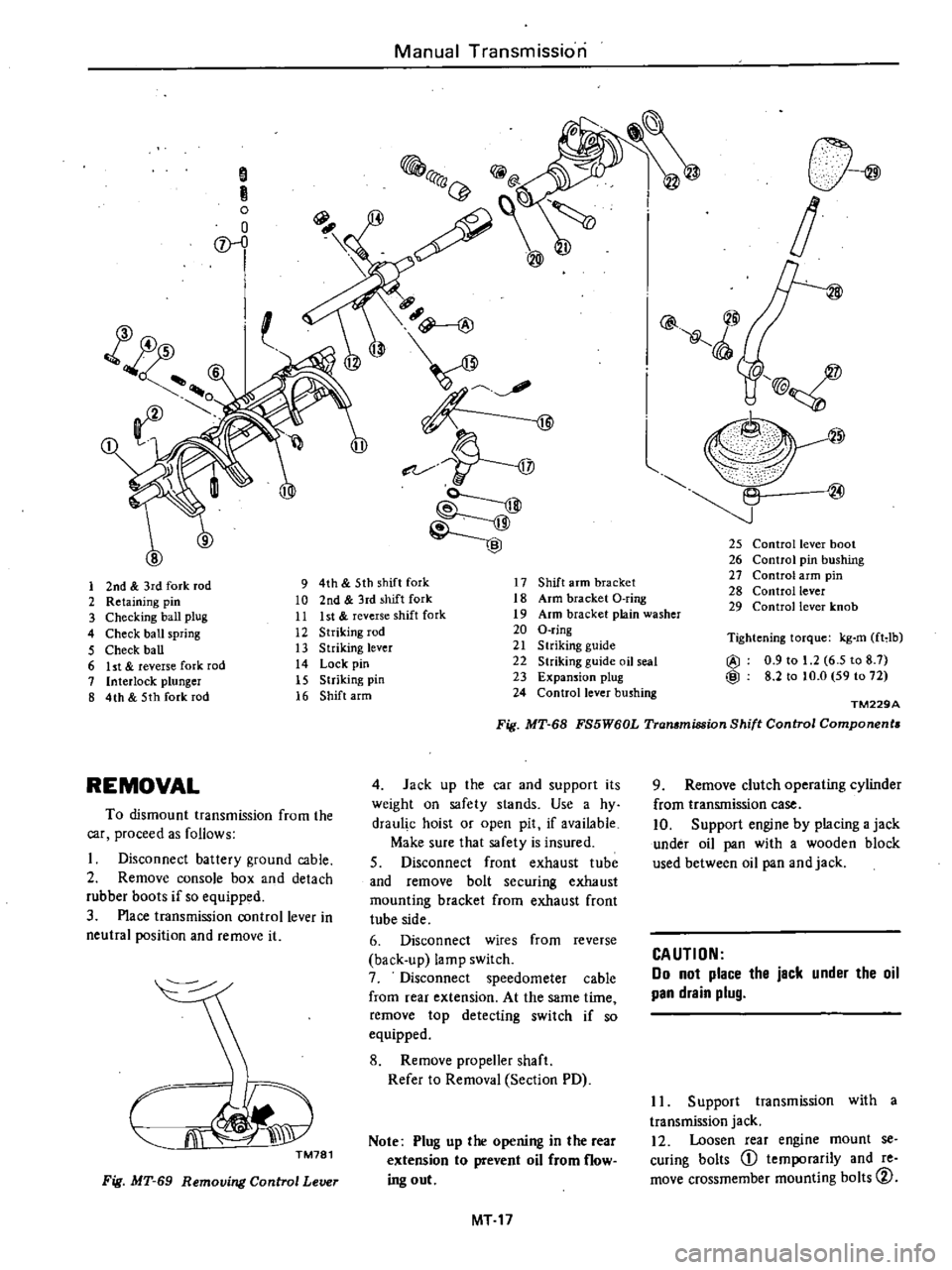
25
Control
lever
boot
26
Control
pin
bushing
27
Control
arm
pin
28
Control
lever
29
Control
lever
knob
1
2nd
3rd
fork
rod
9
4th
5th
shift
fork
17
Shift
arm
bracket
2
Retaining
pin
10
2nd
3rd
shift
fork
18
Arm
bracket
O
ring
3
Checking
ball
plug
11
Ist
reverse
shift
fork
19
Arm
bracket
plain
washer
4
Check
ball
spring
12
Striking
rod
20
O
ring
5
Check
ball
13
Striking
lever
21
S
lriking
guide
6
ht
reverse
fork
rod
14
Lock
pin
22
Striking
guide
oil
seal
7
Interlock
plunger
15
Striking
pin
23
Expansion
plug
8
4th
5th
fork
rod
16
Shift
arm
24
Control
lever
bushing
Tightening
torque
kg
m
fHb
@
0
9
to
1
2
6
5
to
8
7
@
8
2
to
to
O
59
to
72
TM229A
Fig
MT
68
FS5W60L
Transmission
Shift
Control
Components
REMOVAL
4
Jack
up
the
car
and
supporl
its
weight
on
safety
slands
Use
a
hy
draul
c
hoist
or
open
pit
if
available
Make
sure
that
safety
is
insured
S
Disconnect
front
exhaust
tube
and
remove
bolt
securing
exhaust
mounting
bracket
from
exhaust
front
tube
side
6
Disconnect
wires
from
reverse
back
up
lamp
switch
7
Disconnect
speedometer
cable
from
rear
extension
At
the
same
time
remove
top
detecting
switch
if
so
equipped
8
Remove
propeller
shaft
Refer
to
Removal
Section
PD
To
dismount
transmission
from
the
car
proceed
as
follows
Disconnect
battery
ground
cable
2
Remove
console
box
and
detach
rubber
boots
if
so
equipped
3
Place
transmission
control
lever
in
neutral
position
and
remove
it
CJi
J
TM781
Note
Plug
up
the
opening
in
the
rear
extension
to
prevent
oil
from
flow
ing
out
Fig
MT
69
Removing
Control
Lever
MT
17
9
Remove
clutch
operating
cylinder
from
transmission
case
10
Support
engine
by
placing
a
jack
under
oil
pan
with
a
wooden
block
used
between
oil
pan
and
jack
CAUTION
Do
not
place
the
jack
under
the
oil
pan
drain
plug
II
Support
transmission
with
a
transmission
jack
12
Loosen
rear
engine
mount
se
curing
bolts
CD
temporarily
and
re
move
crossmember
mounting
bolts
CV
Page 234 of 548
o
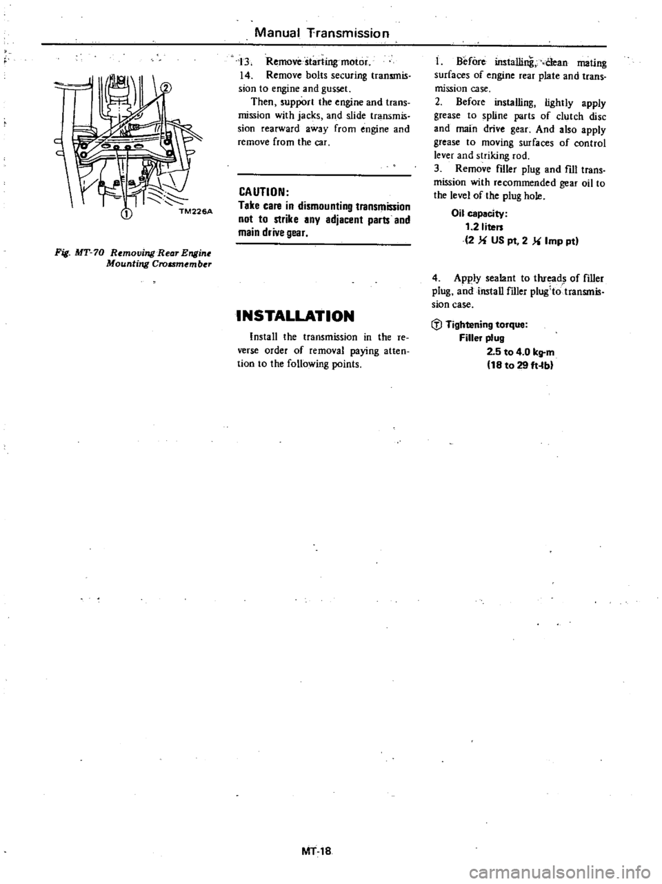
Fig
MT
70
R
movi7l
lB
ar
Ensi
Mounting
Croum
mber
Manual
Transmission
3
Remove
starting
motor
14
Remove
bolts
securing
transmis
sJon
to
engine
and
gusset
Then
support
the
engine
and
trans
mission
with
jacks
and
slide
transmis
sion
rearward
away
from
engine
and
remove
from
the
car
CAUTION
Take
cate
in
dismounting
transmission
not
to
strike
any
adjacenl
parts
and
main
drive
gear
INSTALLATION
Install
the
transmission
in
the
re
verse
order
of
removal
paying
atten
tion
to
the
following
points
MT18
t
Before
installing
Clean
mating
surfaces
of
engine
rear
plate
and
trans
mission
case
2
Before
installing
lightly
apply
grease
to
spline
parts
of
clutch
disc
and
main
drive
gear
And
also
apply
grease
to
moving
surfaces
of
control
lever
and
striking
rod
3
Remove
filler
plug
and
fill
trans
mission
with
recommended
gear
oil
to
the
level
of
the
plug
hole
Oil
capacity
t
2
liters
2
US
pt
2
Imp
ptl
4
Apply
sealant
to
thread
of
filler
plug
and
install
filler
plug
totransmis
sian
case
l
l
Tightening
torque
Filler
plug
2
5
to
4
0
kg
m
t8
to
29
ft
bl
Page 239 of 548
1
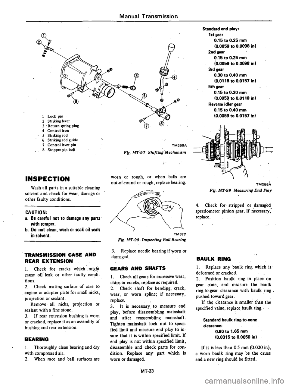
Lock
pin
2
Striking
lever
3
Return
pring
plug
4
Control
lever
5
Striking
rod
6
Striking
rod
guide
7
Control
lever
pin
8
Stopper
pin
bolt
INSPECTION
Wash
all
parts
in
a
suitable
cleaning
solvent
and
check
for
wear
damage
or
other
faulty
conditions
CAUTION
a
Be
careful
not
to
damage
any
parts
with
scraper
b
Do
not
clean
wash
or
soak
oil
seals
in
solvent
TRANSMISSION
CASE
AND
REAR
EXTENSION
1
Check
for
cracks
which
might
cause
oil
leak
or
other
faulty
condi
tions
2
Check
mating
surface
of
case
to
engine
or
adapter
plate
for
small
nicks
projection
or
sealant
Remove
all
nicks
projection
or
sealant
with
a
fine
stone
3
If
rear
extension
bushing
is
worn
or
cracked
replace
it
as
an
assembly
of
bushing
and
rear
extension
BEARING
I
Thoroughly
clean
bearing
and
dry
with
compressed
air
2
When
race
and
ball
surfaces
are
Manual
Transmission
1
TM255A
Fig
MT
97
Shifting
Mechanism
worn
or
rough
or
when
balls
are
out
of
round
or
rough
replace
bearing
TM372
Fig
MT
98
Inspecting
Ball
Bearing
3
Replace
needle
bearing
if
worn
or
damaged
GEARS
AND
SHAFTS
I
Check
all
gears
for
excessive
wear
chips
or
cracks
replace
as
required
2
Check
shaft
for
bendillg
crack
wear
or
worn
spline
if
necessary
replace
3
It
is
necessary
to
measure
end
play
before
disassembling
mainshaft
and
after
reassembling
mainshaft
Tighten
mainshaft
lock
nut
to
speci
fied
limit
and
measure
end
play
to
in
sure
that
it
is
within
specified
limit
If
end
play
is
not
within
specified
limit
disassemble
and
check
parts
for
con
dition
Replace
any
part
which
is
worn
or
damaged
MT
23
Standard
end
play
1
t
gear
0
15
to
0
25
mm
0
0059
to
0
0098
in
2nd
gear
0
15
to
0
25
mm
0
0059
to
0
0098
in
3rd
gear
0
30
to
0
40
mm
0
0118
to
0
0157
in
5th
gear
0
15
to
0
30
mm
0
0059
to
0
0118
in
Reverse
idler
gear
0
15
to
0
40
mm
0
0059
to
0
0157
in
TM256A
Fig
MT
99
Measuring
End
Phly
4
Check
for
stripped
or
damaged
speedometer
pinion
gear
If
necessary
replace
BAULK
RING
I
Replace
any
baulk
ring
which
is
deformed
or
cracked
2
Position
baulk
ring
in
place
on
gear
cone
and
measure
the
baulk
ring
to
gear
clearance
with
baulk
ring
pushed
toward
gear
If
th
clearance
is
smaller
than
the
specified
value
replace
baulk
ring
Standard
baulk
rinltto
cone
dearance
0
80
to
1
65
mm
0
0315
to
0
0650
in
If
it
is
less
than
0
5
mm
0
020
in
a
worn
baulk
ring
may
be
the
cause
and
a
new
ring
should
be
fitted
Page 240 of 548
it
TMS06
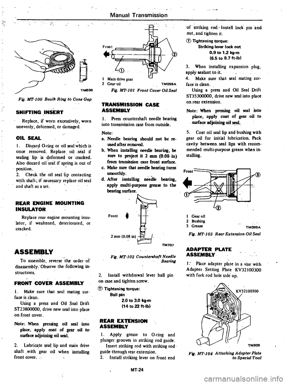
Fig
MT
100
Baulk
Ring
to
Con
Gap
SHiniNG
IIUERT
Replace
if
WOrn
excessively
worn
unevenly
defonned
or
damaged
OIL
SEAL
I
Dis
r
l
O
ring
or
oil
seal
which
is
once
removed
Replace
oil
seal
if
sealing
lip
is
qefonned
or
cracked
Also
discard
oil
seal
if
spring
is
out
of
position
2
Check
tlie
oil
seal
lip
contacting
with
shaft
if
necessary
replace
oil
seal
and
shaft
as
a
set
REAR
ENGINE
MOUNTING
INSULATOR
Replace
rear
engine
mounting
insu
lator
if
weakened
deteriorated
or
cracked
ASSEMBLY
To
assemble
reverse
the
order
of
disassembly
Observe
the
following
in
structions
FRONT
COYER
ASSEMBLY
I
Make
sure
that
seal
mating
sur
face
is
clean
Using
a
press
and
Oil
Seal
Drift
ST23800000
drive
new
seal
into
place
on
front
cover
Nole
When
pressing
oil
seal
into
place
apply
coat
of
gear
oil
to
surface
adjoining
oil
seat
2
Lubrica
te
seal
lip
and
main
drive
shaft
with
gear
oil
when
installing
front
cover
Manual
Transmission
Front
h
I
4
1
Main
drive
gear
2
GearoiJ
TM098A
Fig
MT
101
Front
Cover
Oil
S
al
TRANSMISSION
CASE
ASSEMBLY
I
Press
countershaft
needle
bearing
into
transmission
case
from
outside
Note
a
Needle
bearing
should
not
be
re
used
after
removal
b
When
inslalling
needle
bearing
be
sure
to
project
it
2
mm
0
08
in
from
tramission
case
front
mace
c
Make
sure
that
needle
bearing
torm
smoothly
d
After
instal6ng
needle
bearing
apply
multi
purpose
grease
to
the
bearing
smace
Front
t
2mm
0
08
in
TM707
Fig
MT
I02
Count
haft
N
edle
Bearing
2
Install
withdrawal
lever
ball
pin
on
case
and
tighten
screw
ifl
Tightening
torque
Sail
pin
2
0
to
3
0
kg
m
14
to
22
ft
Ibl
REAR
EXTENSION
ASSEMBLY
I
Apply
grease
to
O
ring
and
plunger
grooves
in
striking
rod
guide
Insert
striking
rod
with
striking
rod
guide
through
rear
extension
2
Install
striking
lever
on
front
end
MT
24
of
striking
rod
Install
lock
pin
and
nut
and
tighten
it
ifl
Tightening
torque
Striking
I
er
lock
nut
0
9
to
12
kg
m
6
5
to
8
7
ft
lbl
3
When
installing
expansion
plug
apply
sealant
to
it
4
Make
sure
that
seal
mating
sur
face
is
clean
Using
a
press
and
Oil
Seal
Drift
ST35300000
drive
new
seal
into
place
on
rear
extension
Note
When
pressing
oil
seal
into
place
apply
coat
of
geat
oil
to
mace
adjoining
oil
seal
5
Coat
oil
seal
lip
and
bushing
with
gear
oil
for
initial
lubrication
Pack
cavity
between
seal
lips
with
recom
mended
multi
purpose
grease
when
in
slalling
FroDt
I
t
Cc
if
i
I
L
1
Gear
oil
2
Bushing
3
Grease
TM099A
Fig
MT
I03
Rear
Eztemion
Oil
Seal
ADAPTER
PLATE
ASSEMBLY
I
Place
adapter
plate
in
a
vise
with
Adapter
Setting
Plate
KV32100JOO
with
fork
rod
hole
side
up
Fig
MT
104
Attaching
AdopterPhlte
to
Special
Tool
Page 249 of 548

TIGHTENING
TORQUE
Ball
pin
Striking
lever
lock
nut
S
llft
arm
bracket
Mainshaft
bearing
retainer
screw
Mainshaft
lock
nut
Rear
extension
installation
bolt
Stopper
pin
bolt
Front
cover
installation
bolt
Speedometer
sleeve
lock
ing
plate
bolt
Top
detecting
switch
Reverse
lamp
switch
Neutral
switch
Return
spring
plug
Gear
oil
filler
plug
Gear
oil
drain
plug
Transmission
to
engine
installation
bolt
Tr
msmissiori
to
engihe
rear
plate
installation
bolt
Transmission
to
gusset
installation
bolt
Starting
motor
to
trans
inissi
n
installation
bolt
Rear
mounting
insulator
to
transmission
installation
bolt
Crossmember
mounting
bolt
Rear
engine
mount
installation
bolt
Clutch
operating
cylinder
installation
bolt
Propeller
shaft
to
differential
carrier
Control
lever
pin
installation
nut
Exhaust
mounting
bracket
to
exhaust
front
tube
FU
model
only
Manual
Transmission
F4W60L
2
0
to
3
0
14
to
22
0
9
to
1
2
6
5
to
8
7
0
7
to
1
0
5
1
to
7
2
1
6
to
2
2
12
to
16
0
5
to
0
8
3
6
to
5
8
1
0
to
1
6
7
to
12
0
3
to
0
5
2
2
to
3
6
2
0
to
3
5
14
to
25
2
0
to
3
5
14
to
25
0
5
to
1
0
3
6
to
7
2
2
5
to
4
0
18
to
29
2
5
to
4
0
18
to
29
1
6
to
2
2
12Jo
16
1
6
to
2
2
12
t
16
4
6
to
6
1
33
to
44
3
0
to
4
0
22
to
29
0
9
to
1
2
6
5
to
8
7
3
2
to
4
3
23
to
31
0
9
to
1
2
6
5
to
8
7
3
1
to
4
1
22
to
30
2
4
to
3
3
17
to
24
1
3
to
1
7
9
to
12
3
2
to
4
3
23
to
31
MT33
Unit
kg
m
ft
lb
FS5W60L
2
0
to
3
0
14
to
22
0
9
to
1
2
6
5
to
8
7
8
2
to
10
0
59
to
72
0
8
to
1
3
5
8
to
9
4
10
0
to
11
0
72
to
80
1
6
to
2
2
12
to
16
1
0
to
1
6
7
to
12
0
3
to
0
5
2
2
to
3
6
2
0
to
3
5
14
to
25
2
0
to
3
5
14
to
25
2
0
to
3
5
14
to
25
0
5
to
1
0
3
6
to
7
2
2
5
to
4
0
18
to
29
i
5
to
4
0
18
to
29
1
6
to
2
2
12
to
16
1
6
to
2
2
12
to
16
4
6
to
6
1
33
to
44
3
0
to
4
0
22
to
29
0
9
to
1
2
6
5
to
8
7
3
2
to
4
3
23
to
31
0
9
to
1
2
6
5
to
8
7
3
1
to
4
1
22
to
30
2
4
to
3
3
17
to
24
1
3
to
1
7
9
to
12
3
2
to
4
3
23
to
31
Page 250 of 548

Manual
Transmission
TROUBLE
DIAGNOSES
AND
CORRECTIONS
Condition
Difficult
to
intermesh
gears
Causes
for
difficult
gear
shifting
are
classi
fie
t
o
ro
lb
c
QncerlJing
coJltr
1
syste
and
transmission
When
gear
shift
lever
is
heavy
and
it
is
difficult
to
shift
gears
clutch
disengagement
may
also
be
unsmooth
First
make
sure
that
clutch
operates
correctly
and
inspect
transmjssion
Gear
slips
out
of
mesh
In
most
cases
this
troubk
occurs
when
check
baD
and
or
spring
is
waIn
or
weaken
ed
or
when
control
system
is
faulty
In
this
case
the
troubk
cannot
be
correct
by
replacing
gears
and
therefore
trouble
shoot
ing
must
be
carried
out
carefuDy
It
should
also
be
noted
that
gear
slips
out
of
mesh
due
to
vibration
generated
by
weakened
front
and
rear
enigne
mounts
Noise
When
noise
occurs
with
engine
idling
and
ceases
when
clutch
is
disengaged
or
when
noise
occurs
while
shifting
gears
it
is
an
indication
that
the
noise
is
from
trans
mission
Transmission
may
rallk
during
engine
idling
Check
air
fuel
mixture
and
ignition
timing
After
above
procedure
readjust
engine
idling
Probable
cause
Worn
gears
shaft
and
or
bearing
Insufficient
operating
stroke
due
to
worn
or
loose
sliding
part
Worn
or
damaged
syncluonizer
Worn
check
baD
and
or
weakened
or
broken
spring
Worn
fork
rod
baU
groove
Worn
or
damaged
bearing
Worn
or
damaged
gear
Insufficient
or
improper
lubricant
Oil
leaking
due
to
damaged
oil
seal
or
sealant
clogged
breather
etc
Worn
bearing
High
humming
occurs
at
a
high
speed
Damaged
bearing
Cyclic
knocking
sound
occurs
also
at
a
low
speed
Worn
spline
Worn
bushing
MT34
Corrective
action
Replace
Repair
ClI
replace
Replace
Replace
Replace
Replace
Replace
Add
oil
or
replace
with
designated
oil
Clean
or
replace
Replace
Replace
Replace
Replace
as
a
rear
ex
tension
assembly
Page 255 of 548

Automatic
Transmission
HYDRAULIC
CONTROL
UNIT
AND
VALVES
The
hydraulic
or
a
tomatic
control
system
is
comprised
of
four
4
basic
groups
the
pressure
supply
system
the
pressure
regulating
system
the
flow
control
valves
and
the
friction
elements
PRESSURE
SUPPLY
SYSTEM
The
pressure
supply
system
consists
of
a
gear
type
oil
pwnp
driven
by
the
engine
through
the
torque
converter
The
pump
provides
pressure
for
aU
hydraulic
and
lubrication
needs
PRESSURE
REGULATOR
VALVES
The
pressure
regulating
valves
con
trol
the
output
pressure
of
the
oil
pump
Pre
ure
rellulator
valve
The
pressure
regulator
valve
con
trois
mainline
pressure
based
on
throttle
opening
for
the
operation
of
the
band
clutches
and
brake
Governor
valve
The
governor
valve
transmits
re
gulated
pressure
based
on
car
peed
to
the
shift
valves
to
control
upshifts
and
downshifts
Vacuum
throttle
valve
The
vacuum
throttle
valve
transmits
regulated
pressure
based
on
engine
load
vacuum
This
pressure
controls
the
pressure
regulator
valve
Also
this
pressure
is
applied
to
one
end
of
the
shift
valves
in
opposition
to
governor
pressure
which
acts
on
the
other
end
of
the
shift
valves
controlling
upshift
and
downshift
speeds
FLOW
CONTROL
VALVES
Manual
valve
The
manual
valve
is
moved
manual
Iy
by
the
car
operator
to
select
the
different
drive
ranges
1
2
ShHt
valve
The
1
2
shift
valve
automaticaIly
shifts
the
transmission
from
first
to
second
or
from
second
to
first
depend
ing
upon
governor
and
throttle
pres
sure
along
with
accelerator
position
solenoid
downshift
valve
See
Hy
draulic
Control
Circuits
Drive
2
2
3
ShHt
valve
The
2
3
shift
valve
automaticaIly
shifts
the
transmission
from
second
to
top
gear
or
from
top
to
second
de
pending
upon
governor
and
throttle
pressure
or
accelerator
position
sole
noid
downshift
valve
See
Hydraulic
Control
Circuits
Drive
3
Range
2
3
Tlmlnll
valve
For
2
3
shifts
a
restrictive
orifice
slows
the
application
fluid
to
the
front
clutch
while
the
slower
reacting
band
is
allowed
to
release
This
prevents
a
hard
2
3
or
3
2
shift
Under
heavy
load
however
the
engine
will
tend
to
run
away
during
the
2
3
or
3
2
shift
pause
therefore
a
2
3
timing
valve
using
throttle
and
governor
pressure
is
used
to
bypass
the
restrictive
orifice
during
such
heavy
load
conditions
Solenoid
down
hHt
valve
The
solenoid
downshift
valve
is
activated
electrically
when
the
ac
celerator
is
f1oor
d
causing
a
forced
downshift
from
top
to
second
top
to
first
or
second
to
first
gear
depending
upon
car
speed
governor
pressure
AT
3
Pre
ure
modified
valve
The
pressure
modifier
valve
assists
the
mainline
pressure
regulator
valve
in
lowering
mainline
pressure
during
high
speed
light
load
conditions
such
as
steady
speed
cruise
Governor
pres
sure
working
against
a
spring
opens
the
valve
which
aUows
modified
throt
tle
pressure
to
work
against
the
pres
sure
regulator
valve
spring
lowering
mainline
pressure
Lower
operating
pressure
under
light
load
reduces
oil
temperature
and
increases
transmis
sian
life
Throttle
back
up
valve
The
throttle
back
up
valve
assists
the
vacuum
throttle
valve
to
increase
line
pressure
when
the
manual
valve
is
shifted
either
to
2
or
I
range
Second
lock
valve
The
second
lock
valve
is
used
to
bypa
the
1
2
shift
valve
to
maintain
the
band
apply
pressure
in
2
posi
tion
The
valve
is
also
used
as
an
oil
passage
for
the
1
2
shift
valve
band
apply
pressure
in
D2
D3
and
12
Range
CLUTCHES
AND
BAND
SERVOS
The
servo
pistons
of
the
clutches
low
reverse
brake
and
band
are
moved
hydraulically
to
engage
the
clutches
brake
and
apply
the
band
The
clutch
and
brake
istons
are
released
by
spring
tension
and
band
piston
is
released
by
spring
tension
and
hy
draulic
pressure
Page 257 of 548
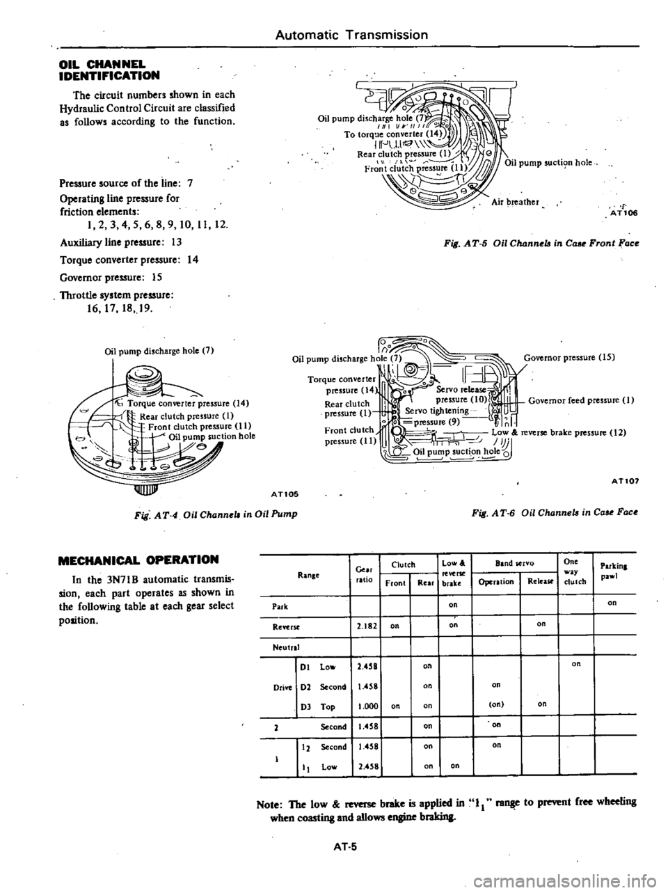
OIL
CHANNEL
IDENTIFICATION
The
circuit
numbers
shown
in
each
Hydraulic
Control
Circuit
are
classified
as
follows
according
to
the
function
Pressure
source
of
the
line
7
Operating
line
pressure
for
friction
elements
I
2
3
4
5
6
g
9
10
11
12
Auxiliary
line
pressure
13
Torque
converter
pressure
14
Governor
pressure
15
Throttle
system
pressure
16
17
18
19
Oil
pump
discharge
hole
7
f
Torque
converter
pressure
14
Rear
clutch
pressure
1
Front
clutch
pressure
11
W
h0i1
pu
6
suction
hote
e
8
IIlIlJJIII
Automatic
Transmission
L
f
AT106
Fig
AT
5
Oil
Channela
in
Cou
Front
Face
lo
o
o
0
Oil
pump
discharge
hole
7
Governor
pressure
15
1
h
Torque
converter
I
pressure
14
0
0
Servo
release
Rear
clutch
l
press
re
10
r
L
Governor
reed
pressure
1
pressure
1
Servo
tlghtemng
li
nb
o
0
pressure
9
r
Front
clutch
fI
Low
reverse
brake
pressure
12
pressure
11
U
0
111
1
1
P
u
n
e
AT107
ATlOS
Fig
A
T
4
Oil
Channell
in
Oil
Pump
Fig
A
T
6
Oil
Channell
in
Cou
Fac
MECHANICAL
OPERATION
In
the
3N71B
automatic
transmis
sion
each
part
operates
as
shown
in
the
following
table
at
each
gear
select
position
RanKe
Cm
ratio
Clutch
Low
A
Front
Rear
brake
One
w
y
dutch
Parkin
pa
l
Band
servo
Operation
Release
Park
on
on
Reftrst
2
182
on
on
on
Neutral
Dl
Lo
2
458
on
on
Drift
02
Second
1
458
on
03
Top
1
000
on
on
on
2
Second
1
4
8
on
on
12
Second
1458
on
on
Low
2
4
8
on
on
Note
The
low
brake
is
applied
in
11
raiW
to
prevent
free
whee6ng
when
coasting
and
aIlows
engine
braking
AT
5
Page 277 of 548
Automatic
Transmission
REMOVAL
AND
INSTALLATION
TRANSMISSION
ASSEMBLY
When
dismounting
the
automatic
transmission
from
a
car
pay
attention
to
the
following
points
I
Before
dismounting
the
trans
mission
rigidly
inspect
it
by
aid
of
the
Trouble
shooting
Chart
and
dis
mount
it
only
when
coll5idered
to
be
necessary
2
Dismount
the
transmission
with
utmost
care
and
when
mounting
observe
the
tightening
torque
indi
cated
on
another
table
not
to
exert
excessive
force
REMOVAL
In
dismounting
automatic
transmis
sion
from
car
proceed
as
follows
I
Disconnect
battery
ground
cable
from
terminal
2
Disengage
torsion
shaft
from
ac
eelerator
linkage
3
Jack
up
vehicle
and
support
its
weight
on
safety
stands
Recommend
a
hydraulic
hoist
or
open
pit
be
utilized
if
available
Make
sure
that
safety
is
insured
4
Remove
propeller
shaft
Note
Pl
ll
up
the
openina
in
the
rear
extension
to
prevent
oil
from
flow
ing
out
S
Disconnect
front
exhaust
tube
6
Disconnect
selector
ra
8e
lever
from
manual
shaft
7
Disconnect
wire
connections
at
inhibitor
switch
8
Disconnect
vacuum
lube
from
vacuum
diaphragm
and
wire
connee
tions
at
downshift
solenoid
9
Disconnect
speedometer
cable
from
rear
exlension
10
Disconnect
oil
charging
pipe
II
Disconnect
oil
cooler
inlet
and
outlet
tubes
al
transmission
case
12
Support
engine
by
locating
a
jack
under
oil
pan
with
a
wooden
block
used
between
oil
pan
and
jack
Support
transmission
by
means
of
a
transmission
jack
CAUTION
Do
not
plecs
the
jack
under
the
oil
pin
dnin
plug
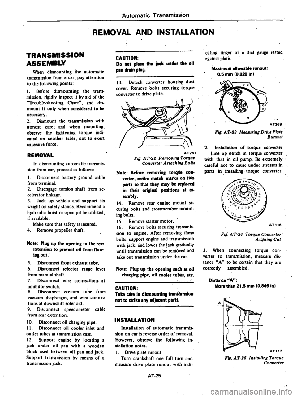
13
Detach
converter
housing
dust
cover
Remove
bolts
securing
torque
converter
to
drive
plate
AT261
Fig
A
T
22
Removi
Torqu
Converter
Attachirrg
Bolt
Note
Before
toni
COD
v
ter
ICnlJe
match
mark
011
two
parts
10
that
they
may
be
replaced
in
their
original
position
at
sa
sembly
14
Remove
rear
engine
mount
Se
curing
bolts
and
crossmember
mount
i
8
bolts
IS
Remove
starter
motor
16
Remove
bolts
securing
transmis
sion
to
engine
After
removing
these
bolts
support
engine
and
transmission
with
jack
and
lower
the
jack
gradually
until
transmission
can
be
removed
and
take
out
transmission
under
the
ear
Note
P1
I
up
the
opening
such
u
oil
chergina
pipe
oil
cooler
tuba
etc
CAUTION
Take
cin
in
dismounting
tnnStnlllioA
not
to
strike
any
adjacent
paru
INSTALLATION
Ill5tallation
of
automatic
transmls
sian
on
car
is
reverse
order
of
removal
However
observe
the
following
in
stallation
notes
Drive
plate
runout
Turn
crankshaft
one
full
turn
and
measure
drive
plate
runout
with
indi
AT
25
eating
finger
of
a
dial
gauge
rested
against
plate
Maximum
ellowable
runout
0
5
mm
0
020
in
AT268
Fig
A
T
3
Me
uring
Drive
PIote
Runout
2
Installation
of
torque
converter
Line
up
notch
in
torque
converter
with
that
in
oil
pump
Be
extremely
careful
not
to
eause
undue
stresses
in
parts
In
inataIIing
torque
converter
AT116
Fig
A
T
24
Torqu
Converter
A
ligning
Cut
3
When
connecting
torque
con
verter
to
transmission
measure
dis
tance
A
10
be
certain
that
they
are
correctly
assembled
Distance
HA
Melre
irian
21
5
mm
0
846
in
A
AT117
Fig
AT
26
1116talling
Torque
Convert
r
Page 278 of 548
4
Bolt
converter
to
drive
plate
Note
Align
chalk
mark
painted
a
cro5S
both
parts
during
disas
sembling
p
S
After
converter
is
installed
rotat
r
nkshait
veral
turns
and
check
to
be
sure
that
transmission
rotates
freely
without
binding
6
Pour
recommended
automatic
transmission
fluid
up
to
correct
level
through
oil
charge
pipe
7
Connect
manual
lever
to
shift
rod
Operation
should
be
carried
out
with
m
mual
and
selector
levers
in
N
8
Connect
inhibitor
switch
wires
Automatic
Transmission
NOte
a
Refer
to
page
AT40
for
Checking
and
Adjusting
Inhibitor
Switch
b
Inspect
end
edjust
switch
as
abo
whe
ever
it
has
to
be
removed
for
servi
e
9
Check
inhibitor
switch
for
op
eration
Starter
should
be
brought
into
op
eration
only
when
selector
lever
is
in
P
and
N
positions
it
should
not
be
started
when
lever
is
in
D
n
and
Ru
positions
Back
up
lamp
should
Iso
light
when
selector
lever
is
placed
in
R
position
10
Check
level
of
oil
in
transm
sion
For
detailed
procedure
see
page
AT39
AT
26
II
Move
selector
leve
through
all
positions
to
be
sure
that
transmission
operates
correctly
With
hand
brake
applied
rotate
engine
at
idling
Without
disturbing
the
above
seUlng
move
selector
lever
through
N
to
D
to
2
to
I
and
to
R
A
slight
shock
should
be
reU
by
handgripping
selector
each
time
transmission
is
shifted
Note
See
page
AT40
for
Checking
Engine
Idling
Revolution
12
Check
to
be
sure
that
line
pres
sure
is
correct
To
do
this
refer
to
page
AT
43
for
Line
Pressure
Test
13
Perform
stan
test
as
described
in
page
AT41