wheel bolts DATSUN 210 1979 User Guide
[x] Cancel search | Manufacturer: DATSUN, Model Year: 1979, Model line: 210, Model: DATSUN 210 1979Pages: 548, PDF Size: 28.66 MB
Page 327 of 548
6
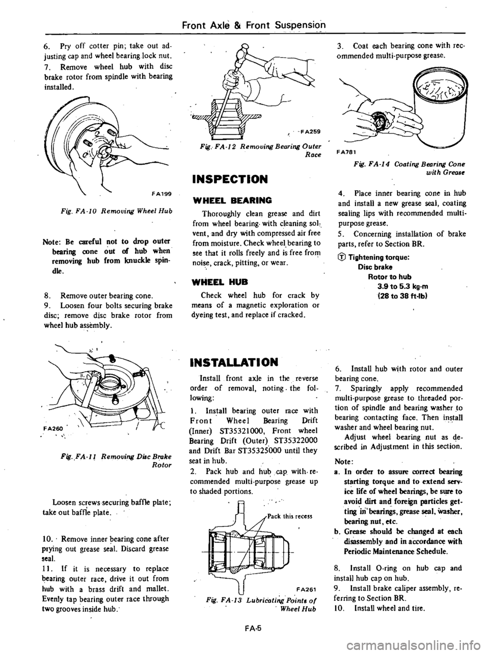
Pry
off
cotter
pin
take
out
ad
justing
cap
and
wheel
bearing
lock
nut
7
Remove
wheel
hub
with
disc
brake
rotor
from
spindle
with
bearing
installed
FA199
Fig
FA
10
Removing
Wheel
Hub
Note
Be
careful
not
to
drop
outer
bearing
DOne
out
of
hub
when
removing
hub
from
knuckle
spin
dle
8
Remove
outer
bearing
cone
9
Loosen
four
bolts
securing
brake
disc
remove
disc
brake
rotor
from
wheel
hub
assembly
Fig
FA
11
Removing
Due
Broke
Rotor
Loosen
screws
securing
baffle
plate
take
out
baffle
plate
10
Remove
inner
earing
cone
after
prying
out
grease
seaL
Discard
grease
seaL
11
If
it
is
necessary
to
replace
earing
outer
race
drive
it
out
from
hub
with
a
brass
drift
and
mallet
Evenly
tap
bearing
outer
race
through
two
grooves
inside
hub
Front
Axle
Front
Suspension
Fig
FA
12
Removing
Bearing
Outer
Race
INSPECTION
WHEEL
BEARING
Thoroughly
clean
grease
and
dirt
from
wheel
bearing
with
cleaning
sol
vent
and
dry
with
compressed
air
free
from
moisture
Check
wheel
bearing
to
see
that
it
rolls
freely
and
is
free
from
noise
crack
pitting
or
wear
WHEEL
HUB
Check
wheel
hub
for
crack
by
means
of
a
magnetic
exploration
or
dyeing
test
and
replace
if
cracked
INSTALLATION
Install
front
axle
in
the
reverse
order
of
removal
noting
the
fol
lowing
I
Install
bearing
outer
race
with
Front
Wheel
Bearing
Drift
Inner
ST35321000
Front
wheel
Bearing
Drift
Outer
ST35322000
and
Drift
Bar
ST35325000
until
they
seat
in
hub
2
Pack
hub
and
hub
cap
with
re
commended
multi
purpose
grease
up
to
shaded
portions
fA261
Fig
FA
13
LubriCating
Points
of
Wheel
Hub
FA
5
3
Coat
each
bearing
DOne
with
rec
ommended
multi
purpose
grease
FA781
Fig
FA
14
Coating
Bearing
Cone
with
Grease
4
Place
inner
bearing
cone
in
hub
and
install
a
new
grease
seal
coating
sealing
lips
with
recommended
multi
purpose
grease
5
Concerning
installation
of
brake
parts
refer
to
Section
BR
i
l
Tightening
tOlque
Disc
brake
Rotor
to
hub
3
9
to
5
3
kg
m
28
to
38
ft
lbl
6
Install
hub
with
rotor
and
outer
bearing
cone
7
Sparingly
apply
recommended
multi
purpose
grease
to
threaded
por
tion
of
spindle
and
bearing
washer
to
bearing
contacting
face
Then
install
washer
and
wheel
bearing
nut
Adjust
wheel
bearing
nut
as
de
scribed
in
Adjustment
in
this
section
Note
a
In
order
to
assure
DOrrect
bearing
starting
torque
and
to
extend
serv
ice
nfe
of
wheel
bearings
be
sure
to
avoid
dirt
and
foreign
particles
get
ting
iIi
bearings
grease
seal
Washer
bearing
nut
etc
b
Grease
should
be
changed
at
each
disassembly
end
in
aa
ordance
with
Periodic
Maintenance
Schedule
8
Install
O
ring
on
hub
cap
and
install
hub
cap
on
hub
9
Install
brake
caliper
assembly
re
ferring
to
Section
BR
10
Install
wheel
and
lire
Page 332 of 548

wheels
2
Remove
splaahboard
if
necessary
3
Back
off
nut
securing
tension
rod
to
bracket
and
remove
bolts
which
secure
tension
rod
to
lower
arm
Tension
rod
can
then
be
taken
out
4
Remove
nuts
securing
stabilizer
bar
to
connecting
rod
Note
Two
wrenches
are
n
1
in
this
B
5
Remove
bolts
and
nuts
securing
stabilizer
bar
bracket
in
position
Stabilizer
bar
can
then
be
iaken
o
t
CV
3
@
I
Lower
ann
5
Tension
rod
2
Stabilizer
bar
bracket
connecting
rod
6
Tension
rod
3
Stabilizer
bar
4
Stabilizer
bar
bracket
FA129
Fig
FA
31
Removing
Tension
Rod
and
Stabilizer
Bar
INSPECTION
I
Check
tension
rod
and
stabilizer
bar
for
evidence
of
deformation
or
cracks
if
necessary
replace
2
Check
rubber
parts
such
as
ten
sion
rod
and
stabilizer
bar
bushings
to
be
sure
they
are
not
deteriorated
or
cracked
if
1ecessary
replace
INSTAllATION
Install
tension
rod
and
stabilizer
bar
in
tJ
1e
reverse
order
of
removal
noting
the
following
I
Be
sure
stabilizer
bar
is
not
closer
to
either
side
but
is
located
at
the
middle
If
stabilizer
bar
is
new
use
the
following
procedure
to
center
the
stabilizer
bar
Position
arm
with
white
paipt
mark
toward
left
side
of
car
Front
Axle
Front
Suspension
Set
slabillz
rliar
mount
bushingS
So
that
outer
side
of
stabilizer
bar
bushing
is
brought
into
inner
side
of
marking
e
o
I
19
e
1
Marking
2
Bushing
3
Marking
4
While
painting
5
Marking
0
A
F
A667
Fig
FA
32
Centering
8lDbilize
Bar
2
Chec
to
be
sure
that
tension
rod
bushing
is
propelly
centered
in
its
seat
3
Be
sure
that
tension
rod
bracket
bolt
is
correctly
torqued
Note
a
Noting
direction
of
tension
rod
bushing
properly
center
bushing
in
tension
rod
bushing
washer
Fig
FA
33
Direclion
of
Tension
Rod
BUlhing
b
After
installation
make
sure
mini
mum
clearances
between
tension
rods
end
stabilizer
bar
are
equal
on
both
sides
c
Closely
observe
torq
ue
specification
when
tightening
tension
rod
bracket
retaining
bolts
d
First
tighten
tension
rod
on
bracket
side
to
specified
torque
setting
then
install
the
other
end
on
lower
arm
fJ
Tightening
tOlque
Tension
rod
bushing
installation
nut
4
5
to
5
11rg
33
to
37
ft
lbl
FA
10
Tension
rOd
to
Lower
ann
5
1
to
6
1
kg
m
137
to
44
ft
Ibl
Tension
rod
bracket
to
body
3
2
to
4
3
kg
m
23
to
31
ft
Ibl
Stabilizer
bar
bleck
t
1
6to2
11rg
112
to
15
ft
lbl
Stabilizel
bel
connecting
rod
1
6
to
2
1
kg
m
12
to
15
ft
lbl
LOWER
ARM
AND
LOWER
BALL
JOINT
The
lower
ann
is
connected
to
the
suspension
member
through
a
rubber
bwhing
end
to
the
strut
through
a
ball
joint
The
lower
ball
joint
is
assembled
at
the
factory
and
cannot
be
disassem
bled
REMOVAL
1
Block
rear
wheels
with
chocks
2
Jack
up
front
of
car
and
support
it
with
safety
stands
remove
wheel
3
Remove
splashboard
4
Separate
knuckle
arm
from
strut
5
Pry
colter
pin
off
and
separate
side
rod
fromknilckle
arm
using
Ball
Joint
Remover
HT72520000
FA661
Fig
FA
34
Remoliing8ideRod
Ball
Joint
6
Remove
tension
rod
and
stabilizer
bar
from
lower
ann
7
Remove
bolt
connecting
lower
ann
to
suspension
crossmember
Page 339 of 548
Front
Axle
Front
Suspension
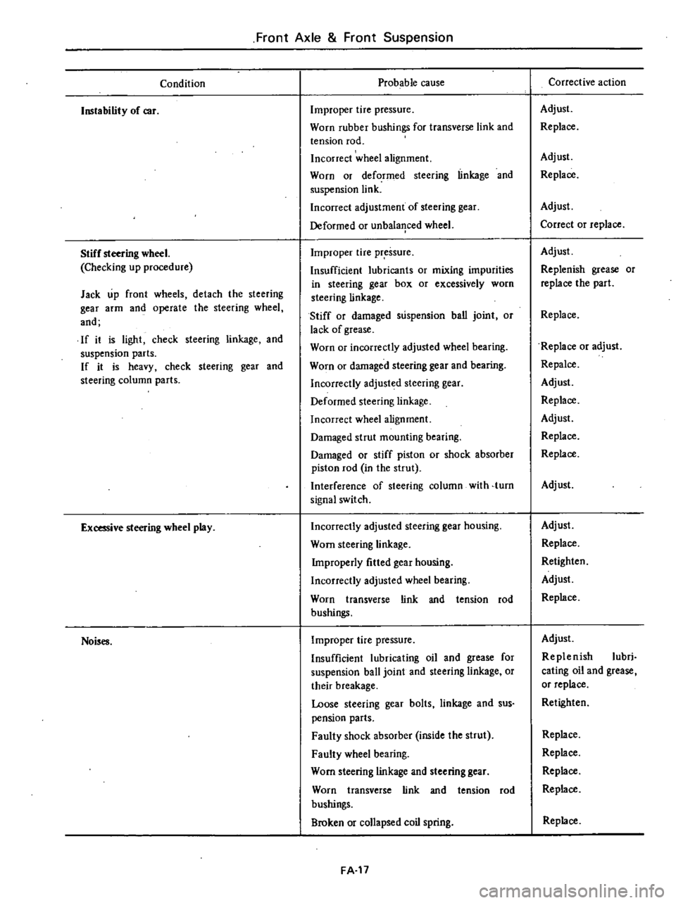
Condition
Instability
of
car
Stiff
steering
wheel
Checking
up
procedure
Jack
up
front
wheels
detach
the
steering
gear
arm
and
operate
the
steering
wheel
and
If
it
is
light
check
steering
linkage
and
suspension
parts
If
it
is
heavy
check
steering
gear
and
steering
column
parts
Excessive
steering
wheel
play
Noises
Probable
cause
Improper
tire
pressure
Worn
rubber
bushings
for
transverse
link
and
tension
rod
Incorrect
wheel
alignment
Worn
or
deformed
steering
linkage
and
suspension
link
Incorrect
adjustment
of
steering
gear
Deformed
or
unbala
1ced
wheel
Improper
tire
pressure
Insufficient
lubricants
or
mixing
impurities
in
steering
gear
box
or
excessively
worn
steering
linkage
Stiff
or
damaged
suspension
ban
joint
or
lack
of
grease
Worn
or
incorrectly
adjusted
wheel
bearing
Worn
or
damaged
steering
gear
and
bearing
Incorrectly
adjusted
steering
gear
Deformed
steering
linkage
Incorrect
wheel
alignment
Damaged
strut
mounting
bearing
Damaged
or
stiff
piston
or
shock
absorber
piston
rod
in
the
strut
Interference
of
steering
column
with
turn
signal
switch
Incorrectly
adjusted
steering
gear
housing
Worn
steering
linkage
Improperly
fitted
gear
housing
Incorrectly
adjusted
wheel
bearing
Worn
transverse
link
and
tension
rod
bushings
Improper
tire
pressure
Insufficient
lubricating
oil
and
grease
for
suspension
ball
joint
and
steering
linkage
or
their
breakage
Loose
steering
gear
bolts
linkage
and
sus
pension
parts
Faulty
shock
absorber
inside
the
strut
Faulty
wheel
bearing
Worn
steering
linkage
and
steering
gear
Worn
transverse
link
and
tension
rod
bushings
Broken
or
collapsed
coil
spring
FA
17
Corrective
action
Adjust
Replace
Adjust
Replace
Adjust
Correct
or
replace
Adjust
Replenish
grease
or
replace
the
part
Replace
Replace
or
adjust
Repalce
Adjust
Replace
Adjust
Replace
Replace
Adjust
Adjust
Replace
Retighten
Adjust
Replace
Adjust
Replenish
lubri
cating
oil
and
grease
or
replace
Retighten
Replace
Replace
Replace
Replace
Replace
Page 340 of 548
Front
Axle
Front
Suspension
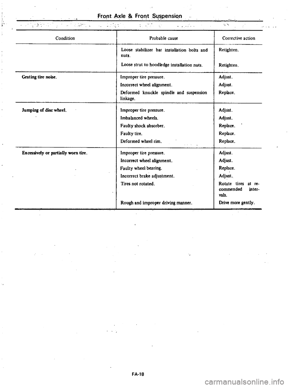
Condition
Probable
cause
Loose
stabilizer
bar
installation
bolts
and
nuts
Loose
strut
to
hoodledge
installation
nuts
Grating
tire
noise
Improper
tire
pressure
Incorrect
wheel
alignment
Deformed
knuckle
spindle
and
suspension
linkage
Jumping
of
disc
wheel
Improper
tire
pressure
Imbalanced
wheels
Faulty
shock
absorber
Faulty
tire
Deformed
wheel
rim
Ex
t
J1
or
partially
worn
tire
Improper
tire
pressure
Incorrect
wheel
alignment
Faulty
wheel
bearing
Incorrect
brake
adjustment
Tires
not
rotated
Rough
and
improper
driving
manner
FA
18
Corrective
action
Retighten
Retighten
Adjust
Adjust
Replace
Adjust
Adjust
Replace
Replace
Replace
Adjust
Adjust
Replace
Adjust
Rotate
tires
commended
vaIs
Drive
more
gently
at
re
inter
Page 344 of 548

REAR
AXLE
REAR
AXLE
ASSEMBLY
Remove
L
Block
front
wheels
with
chocks
2
Raise
rear
of
car
high
enough
to
pennit
working
underneath
and
place
stands
solidly
under
body
member
on
both
sides
RA544
Fig
RA
2
Supporting
Point
3
Support
under
center
of
dif
ferential
carrier
with
a
garage
jack
4
Remove
rear
wheels
5
Disconnect
propeller
shaft
by
re
moving
bolts
CD
securing
propeller
shaft
flange
to
companion
flange
of
differential
carrier
6
Disconnect
brake
hose
from
brake
tube
at
body
@
and
rear
cable
adjuster
@
Fig
RA
3
Removing
Propeller
Shaft
and
Brohe
Hose
CAUTION
e
When
disconnecting
brake
tube
use
suitable
tube
wrench
Never
use
open
end
or
adjustable
wrench
b
Cover
brake
hose
end
pipe
open
ings
to
prevent
entrance
of
dirt
Rear
Axle
Rear
Suspension
7
Remove
bolts
securing
shock
absorber
lower
ends
on
each
side
RA485
Fig
RA
4
Removing
Bolt
Securing
Shock
Absorber
Lower
End
Note
When
removing
shock
absorber
lower
end
from
bracket
squeeze
shock
absorber
and
lift
it
out
right
above
to
accommodate
em
bossment
inside
bracket
C
AA486
Fig
RA
5
Shock
Absorber
Lower
End
8
Lower
jack
slowly
and
remove
cojI
springs
on
each
side
after
they
are
fully
extended
AA546
Fig
RA
6
Removing
Coil
Spring
9
Raise
jack
to
its
original
position
10
Remove
bolts
CD
and
@
se
curing
upper
and
lower
links
at
axle
case
side
RA
3
Fig
RA
7
Disconnecting
Upper
Link
and
Lower
Link
II
Release
garage
jack
slowly
and
pull
it
out
toward
rear
of
car
In
tenetlon
Install
rear
axle
in
the
reverse
order
of
removal
CAUTION
a
When
installing
brake
tubes
use
Flare
Nut
Torque
Wrench
GG94310000
b
Before
tightening
link
bushing
nuts
temporarily
attach
upper
and
lower
links
to
axle
case
Alter
jacking
up
center
of
differential
carrier
until
upper
Bnd
lower
links
are
almost
horizontal
securely
tighten
link
bushing
nuts
c
When
supporting
car
weight
at
Cl
nter
of
differential
carrier
do
not
put
a
load
in
car
j
Tightening
torque
Brake
tube
flare
nut
1
5
to
1
8
kg
m
11
to
13
ft
lb
Propeller
shaft
to
companion
flange
connecting
nut
2
4
to
3
3
kg
m
17
to
24
ft
Ibl
Shock
absorber
lower
end
nut
7
0
to
8
0
kg
m
51
to
58
ft
Ibl
lower
link
fixing
nut
7
0
to
8
0
kg
m
51
to
58
ft
Ib
Upper
link
fixing
nut
7
0
to
8
0
kg
m
51
to
58
ft
lb
Page 347 of 548

I
AA552
Fig
RA
18
Shock
A
bllOrber
Upper
End
2
Remove
bolt
securing
shock
ab
sorber
lower
end
and
remove
shock
absorber
Note
When
removing
shock
ebsorber
lower
end
from
bracket
Iueeze
shock
absorber
end
lift
it
out
right
aJ
o
J
to
accommodate
emb
ss
ment
inside
bracket
c
RA486
Fig
RA
19
Shock
Absorber
Lower
End
Brocket
Inspection
I
Test
shock
absorber
and
compare
with
specification
given
in
Service
Data
and
Specifications
Replace
if
nece
ry
2
Check
for
cracks
Also
check
pis
ton
rod
for
straightness
3
Check
all
rubber
parts
for
wear
cracks
damage
or
deformation
Re
place
if
necessary
Installation
Install
shock
absorber
in
the
reverse
order
of
removal
Note
Tighten
shock
absorber
upper
end
nut
to
specification
until
it
is
fully
tightened
to
thread
end
of
pis
ton
rod
Then
securely
tighten
lock
nut
Rear
Axle
Rear
Suspension
@
Tightening
tonlU1l
Shock
absorber
upper
end
nut
1
5
to
2
0
kg
m
11
to
14
ft
b
Shock
absorber
lower
end
n1
t
7
0
to
8
0
k
l
m
51
to
58
ft
bl
CAUTION
I
Be
careful
not
to
damage
or
bend
piston
rod
during
operation
b
Do
not
open
or
heat
gas
filled
type
shock
absorbers
COIL
SPRING
Removal
Block
front
wheels
with
chocks
2
Raise
rear
of
car
high
enough
to
permit
working
underneath
and
place
stands
solidly
under
body
member
on
both
sides
3
Support
under
center
of
dif
ferential
carrier
with
a
garage
jack
4
Remove
rear
wheels
5
Remove
bolts
securing
shock
absorber
lower
ends
on
each
side
C
J
1
v
I
JJJ
RA485
Fig
RA
20
RemoviTIII
Bolt
Securing
Shock
Abwrber
Lower
End
6
Lower
jack
slowly
and
remove
coil
springs
on
each
side
after
they
are
fully
extended
RA546
Fig
RA
21
Removing
Coil
Spring
RA
6
Inspection
1
Check
coil
spring
for
yield
defor
mation
or
cracks
2
Test
spring
and
compare
with
specifications
given
in
Service
Data
and
Specifications
3
Check
all
rubber
parts
for
wear
cracks
damage
or
deformation
Re
place
if
necessary
InsteDatlon
Install
coil
spring
in
the
reverse
order
ofremoval
CAUTION
Correctly
fit
open
end
on
spring
seat
CD
Tightening
torque
Shock
absorber
lowel
end
nut
7
010
8
0
kg
51
to
58
ft
b
LINK
ASSEMBLY
Removal
It
is
possible
to
remove
one
link
assembly
alone
When
removing
more
than
two
link
assemblies
remove
axle
assembly
first
Refer
to
Rear
Axle
Assembly
for
removal
Remove
upper
link
or
lower
link
alone
by
removing
bolt
on
each
end
Fig
RA
22
Removing
Upper
Link
RA553
Fig
RA
23
Remouing
Lower
Link
Page 351 of 548
Rear
Axle
Rear
Suspension
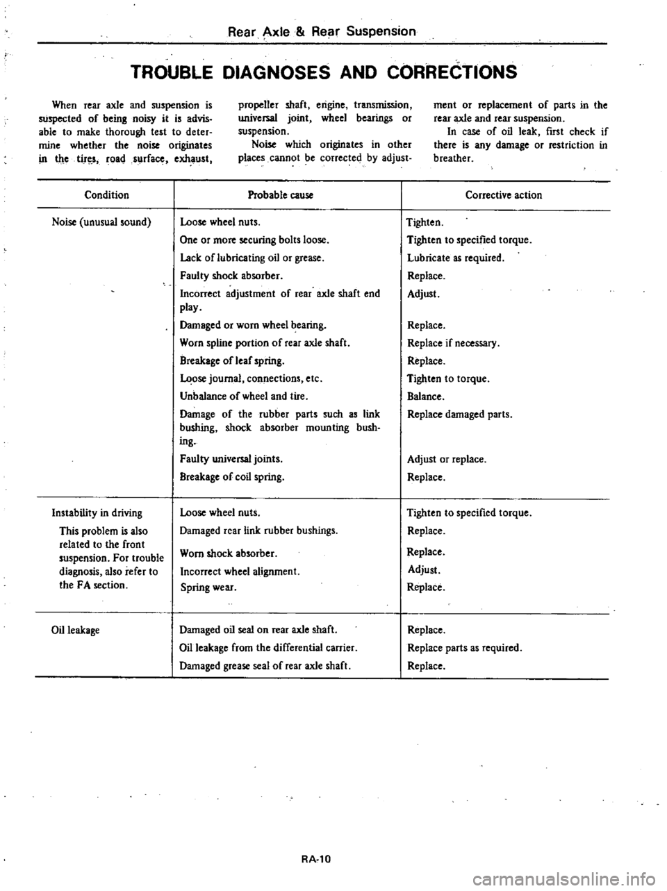
TROUBLE
DIAGNOSES
AND
CORRECTIONS
When
rear
axle
and
suspension
is
suspected
of
being
noisy
it
is
advis
able
to
make
thorough
test
to
deter
mine
whether
the
noise
originates
in
the
tir
s
roads
rfac
exhaust
propeller
shaft
engine
transmission
universal
joint
wheel
bearings
or
suspension
Noise
which
originates
in
other
places
cannot
be
corrected
by
adjust
Condition
Noise
unusual
sound
Instability
in
driving
This
problem
is
also
related
to
the
front
suspension
For
trouble
diagnosis
also
refer
to
the
FA
section
Oil
leakage
Probable
cause
Loose
wheel
nuts
One
or
more
securing
bolts
loose
Lack
oflubricating
oil
or
grease
Faulty
shock
absorber
Incorrect
adjustment
of
rear
axle
shaft
end
play
Damaged
or
worn
wheel
bearing
Worn
spline
portion
of
rear
axle
shaft
Breakage
of
leaf
spring
ose
journal
connections
etc
Unbalance
of
wheel
and
tire
Damage
of
the
rubber
parts
such
as
link
bU
hing
shock
absorber
moun
ting
bush
ing
Faulty
universal
joints
Breakage
of
coil
spring
Loose
wheel
nuts
Damaged
rear
link
rubber
bushings
Worn
shock
absorber
Incorrect
wheel
alignment
Spring
wear
Damaged
oil
seal
on
rear
axle
shaft
Oil
leakage
from
the
differential
carrier
Damaged
grease
seal
of
rear
axle
shaft
RA
l0
ment
or
replacement
of
parts
in
the
rear
axle
and
rear
suspension
In
case
of
oil
leak
first
check
if
there
is
any
damage
or
restriction
in
breather
Corrective
action
Tighten
Tighten
to
specified
torque
Lubricate
as
required
Replace
Adjust
Replace
Replace
if
necessary
Replace
Tighten
to
torque
Balance
Replace
damaged
parts
Adjust
or
replace
Replace
Tighten
to
specified
torque
Replace
Replace
Adjust
Replace
Replace
Replace
parts
as
required
Replace
Page 359 of 548
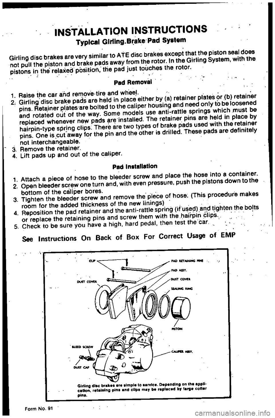
INSTALLATION
INSTRUCTIONS
Typical
Glrllng
B
ake
Pad
SYIlem
Girling
disc
brakes
are
very
similar
to
ATE
disc
brakes
except
that
the
piston
seal
does
not
pul
the
piston
and
brake
pads
away
from
the
rotor
In
the
Girling
System
with
the
pistons
i
the
relaxeilposition
the
pad
just
touches
the
rotor
Ped
Removal
1
Raise
the
car
alid
removiHire
and
wheel
2
Girling
disc
brake
pads
ere
held
in
piece
either
by
a
retainer
plates
or
b
retainer
pins
Retainer
plates
are
boiled
to
the
caliper
housing
and
need
only
to
be
loosened
and
roteted
out
of
the
way
Some
models
use
anti
raWe
springs
which
must
be
replaced
whenever
new
pads
ere
installed
The
retainer
pins
are
held
in
place
by
hairpin
type
spring
clips
There
are
two
types
of
breke
pads
used
with
the
retainer
pins
One
is
cut
away
for
the
pin
end
the
other
is
drilled
These
padS
ere
definitely
not
interchengeable
3
Remove
the
reteiner
4
Lift
padS
up
and
out
of
the
celiper
Pad
Installation
1
Attach
a
piece
of
hose
to
the
bleeder
screw
and
place
the
hose
into
a
container
2
Open
bleeder
screw
one
turn
and
with
even
pressure
push
the
pistons
down
to
the
bottom
of
the
caliper
bores
3
Tighten
the
bleeder
screw
and
remove
the
piece
o
hose
This
procedure
makes
room
for
the
added
thickness
of
the
new
linings
4
Reposition
the
pad
retainer
and
the
anti
rattle
spring
i
used
and
tighten
the
bolts
or
replace
the
retaining
pins
and
screw
them
with
the
hairpin
Iips
5
Check
to
be
sure
you
have
a
high
hard
pedal
then
test
the
car
See
Instructions
On
Back
of
Ball
For
Correct
Usage
of
EMP
Gh11ng
dlac
brall
Ilmple
to
art
lc
Depending
III
ppU
aUon
atalnln
pilla
nd
clip
may
blt
placed
by
larga
QU
pin
Form
No
91
Page 361 of 548

BR563
Fig
BR
10
Removing
Pad
Inspection
Clean
pads
with
cleaning
solvent
CAUTION
Use
brake
fluid
to
clean
Never
use
mineral
oil
2
When
pads
are
heavily
fouled
with
oil
or
grease
or
when
pad
is
deteriorated
or
deformed
replace
it
3
If
pad
is
worn
to
less
than
the
specified
value
replace
Pad
wear
limit
Minimum
thickness
t
6
mm
0
063
in
Note
Always
replace
pads
in
pad
kit
four
pads
two
clips
four
pad
pins
and
four
pad
springs
4
Check
rotor
referring
to
Rotor
for
inspection
Installetlon
I
Clean
and
apply
P
RC
grease
on
yoke
guide
groove
of
cylinder
body
sliding
contact
portions
of
yoke
and
end
surface
of
piston
Note
a
Do
not
use
common
brake
grease
b
Be
careful
not
to
get
brake
grease
on
rotor
and
pads
2
Loosen
air
bleeder
and
push
pis
ton
B
outer
piston
in
cylinder
until
end
surface
of
piston
B
coincides
with
end
surface
of
retaining
ring
on
boot
Then
inner
pad
can
be
installed
Brake
System
BR564
Fig
BR
11
Pushing
Piston
CAUTION
Piston
can
be
easily
pushed
in
by
hand
but
if
pushed
too
far
groove
of
piston
will
go
inside
of
piston
seal
as
shown
in
Fig
BR
12
At
this
point
if
piston
is
pressured
or
moved
piston
seal
will
be
damaged
If
piston
has
been
pushed
in
too
far
remove
brake
assembly
and
disassemble
it
Then
push
piston
out
in
the
direction
shown
by
arrow
Assemble
it
again
referring
to
follow
ing
section
00
I
Normal
I
position
L
BR409
Fig
BR
12
Position
for
Pushing
Piston
3
Push
piston
A
inner
piston
in
cylinder
by
pulling
yoke
as
shown
The
outer
pad
can
then
be
installed
BRS6S
Fig
BR
13
Pulling
in
Piston
A
BR
7
4
After
installing
pads
depress
brake
pedal
several
times
and
pads
will
settle
into
proper
position
Note
When
worn
out
pads
are
re
placed
with
new
ones
brake
fluid
may
overflow
reservoir
While
re
placing
pads
keep
loosening
bleeder
to
release
brake
fluid
5
Install
wheels
and
lower
car
to
ground
REMOVAL
I
Remove
pads
Refer
to
Pad
Re
placement
2
Remove
brake
tube
from
caliper
assembly
CAUTION
When
removing
brake
tube
use
suit
able
tube
wrench
Never
use
open
end
or
adjustable
wrench
Note
Plug
up
hole
in
caliper
so
that
brake
fluid
does
not
flow
out
from
cylinder
body
3
Loosen
bolts
securing
cylinder
body
to
knuckle
spindle
and
remove
caliper
assembly
from
strut
DISASSEMBLY
I
Drain
brake
fluid
from
top
hole
of
cylinder
body
2
Push
both
pistons
A
and
B
into
cylinder
Refer
to
Pad
Replacement
3
Tap
cylinder
body
lightly
with
a
plastic
hammer
Cylinder
will
then
separate
from
yoke
BR115A
Fig
BR
14
Tapping
Cylinder
Block
Page 363 of 548

6
Apply
P
B
C
grease
to
yoke
slid
ing
part
of
cylinder
Then
reposition
bias
ring
so
that
groove
of
bias
ring
coincides
with
yoke
7
Leaving
yoke
springs
inserted
lightly
into
cylinder
groove
assemble
cylinder
body
and
yoke
by
pushing
or
tapping
yoke
lightly
BA570
Fig
BR
19
A
embling
Yoke
and
Cylinder
8
Install
air
bleeder
valve
on
caliper
INSTAlLATION
1
Install
in
reverse
procedure
of
removal
CAUTION
When
installing
brake
tube
use
Flare
Nut
Torque
Wrench
6694310000
fJ
Tightening
tOlque
Calipel
securing
bolts
4
6
to
6
1
kll
m
33
to
44
ft
lb
Brake
tube
flere
nuts
1
5to
1
8
kg
m
11
to
13
ft
Ib
2
After
installing
pad
bleed
air
from
system
Brake
System
ROTOR
REMOVAL
Refer
to
Front
Axle
Section
FA
for
removal
Note
As
this
value
increases
wear
occurs
progressively
vibration
cor
responding
to
revolution
of
tire
may
often
be
tmnsmitted
to
in
terior
of
car
INSPECTION
Check
the
following
items
and
if
necessary
replace
Checks
can
be
made
by
removing
only
wheel
Sliding
surface
If
there
are
cracks
or
considerable
chips
replace
2
Runout
Adjust
wheel
bearing
correctly
Using
a
dial
gauge
measure
runout
at
the
center
of
rotor
pad
contact
sur
face
Runout
limit
less
than
0
12
mm
0
0047
in
Total
indicator
reading
BR025A
Fig
BR
20
Mecuuring
Runout
3
Parallelism
Measure
thickness
of
entire
periph
cry
of
rotor
using
a
micrometer
Parallelism
when
new
less
than
0
03
mm
0
0012
in
BR
9
Fig
BR
21
Measuring
Parallelism
4
Thickness
If
rotor
thickness
is
beyond
wear
limit
replace
rotor
When
correcting
thickness
be
sure
that
the
thickness
after
correction
does
not
exceed
the
limit
Standard
thickness
10
0
mm
0
394
in
Wear
limit
more
than
8
4
mm
0
331
in
INSTALLATION
Install
rotor
in
reverse
order
of
removal
Adjust
wheel
bearing
preload
correctly
Refer
to
Front
Axle
Sec
tion
FA
for
adjustment
ifl
Tightening
torque
Rotor
to
wheel
hub
3
9
to
5
3
kg
m
28
to
38
ft
rb