steering DATSUN 210 1979 Owner's Guide
[x] Cancel search | Manufacturer: DATSUN, Model Year: 1979, Model line: 210, Model: DATSUN 210 1979Pages: 548, PDF Size: 28.66 MB
Page 396 of 548
Steering
System
Side
rod
Standard
side
rod
length
mm
in
315
12
40
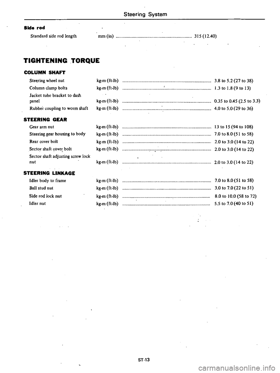
TIGHTENING
TORQUE
COLUMN
SHAFT
Steering
wheel
nut
kg
m
ft
lb
3
8
to
5
2
27
to
38
Column
clamp
bolts
kg
m
ft
lb
I
3
to
1
8
9
to
13
Jacket
tube
bracket
to
dash
panel
kg
m
ft
lb
0
35
to
0
45
2
5
to
3
3
Rubber
coupling
to
worm
shaft
kg
m
ft
lb
4
0
to
5
0
29
to
36
STEERING
GEAR
Gear
arm
nut
kg
m
ft
lb
13
to
15
94
to
108
Steering
gear
housing
to
body
kg
m
ft
lb
7
0
to
8
0
51
to
58
Rear
cover
bolt
kg
m
ft
lb
2
0
to
3
0
14
to
22
Sector
shaft
cover
bolt
kg
m
ft
lb
2
0
to
3
0
14
to
22
Sector
shaft
adjusting
screw
lock
nut
kg
m
ft
lb
2
0
to
3
0
14
to
22
STEERING
LINKAGE
Idler
body
to
frame
kg
m
ft
lb
7
0
to
8
0
51
to
58
Ball
stud
nut
kg
m
ft
lb
3
0
to
7
0
22
to
51
Side
rod
lock
nut
kg
m
ft
lb
8
0
to
10
0
58
to
72
Idler
nut
kg
m
ft
lb
5
5
to
7
0
40
to
51
ST
13
Page 397 of 548
Steering
System
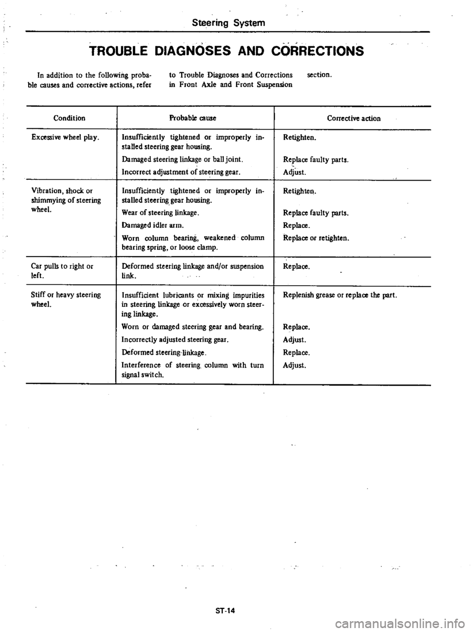
TROUBLE
DIAGNOSES
AND
CORRECTIONS
In
addition
to
the
following
proba
ble
causes
and
corrective
actions
refer
to
Trouble
Diagnoses
and
Corrections
in
Front
Axle
and
Front
Suspension
section
Condition
Excessive
wheel
play
Vibration
shock
or
shimmying
of
steering
wheel
Car
pulls
to
right
or
left
Stiff
or
heavy
steering
wheel
Probable
cause
Insufficiently
tightened
or
ilnproperly
in
stalled
steering
gear
housing
Damaged
steering
linkage
or
ball
joint
Incorrect
adjustment
of
steering
gear
Insufficiently
tightened
or
ilnproperly
in
stalled
steering
gear
housing
Wear
of
steering
linkage
Damaged
idler
arm
Worn
column
bearing
weakened
column
bearing
spring
or
loose
clamp
Deformed
steering
linkage
and
or
suspension
link
Insufficient
lubricants
or
mixing
impurities
in
steering
linkage
or
excessively
worn
steer
ing
linkage
Worn
or
damaged
steering
gear
and
bearing
Incorrectly
adjusted
steering
gear
Deformed
steering
liilkage
Interference
of
steering
column
with
turn
signal
switch
ST
14
Corrective
action
Retighten
Re
lace
faulty
parts
Adjust
Retighten
Replace
faulty
parts
Replace
Replace
or
retighten
Replace
Replenish
grease
or
replace
the
part
Replace
Adjust
Replace
Adjust
Page 398 of 548
Steering
System
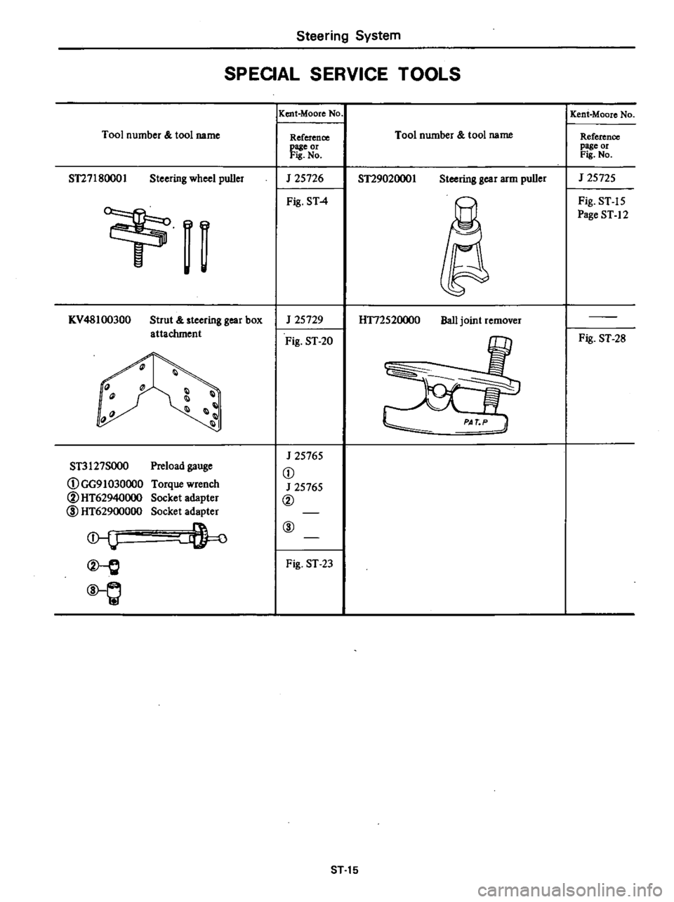
SPEOAL
SERVICE
TOOLS
Tool
number
tool
name
ST27180001
Steering
wheel
puller
n
I
KV
48100300
Strut
steering
gear
box
attachment
1l
1
III
11
Preload
gauge
Torque
wrench
Socket
adapter
Socket
adapter
ST3127SOO0
DGG91030000
@HT62940000
l
HT62900000
l
Q
IKent
Moore
No
Reference
page
or
Fis
No
J
25726
Fig
ST
4
J
25729
Fig
ST
20
J
25765
D
J
25765
@
@
Fig
ST
23
Tool
number
tool
name
ST29020001
Steering
gear
arm
puller
H172520000
Ball
joint
remover
ST
15
Kent
Moore
No
Reference
page
or
Fis
No
J
25725
Fig
ST
15
Page
ST
12
Fig
ST
28
Page 440 of 548
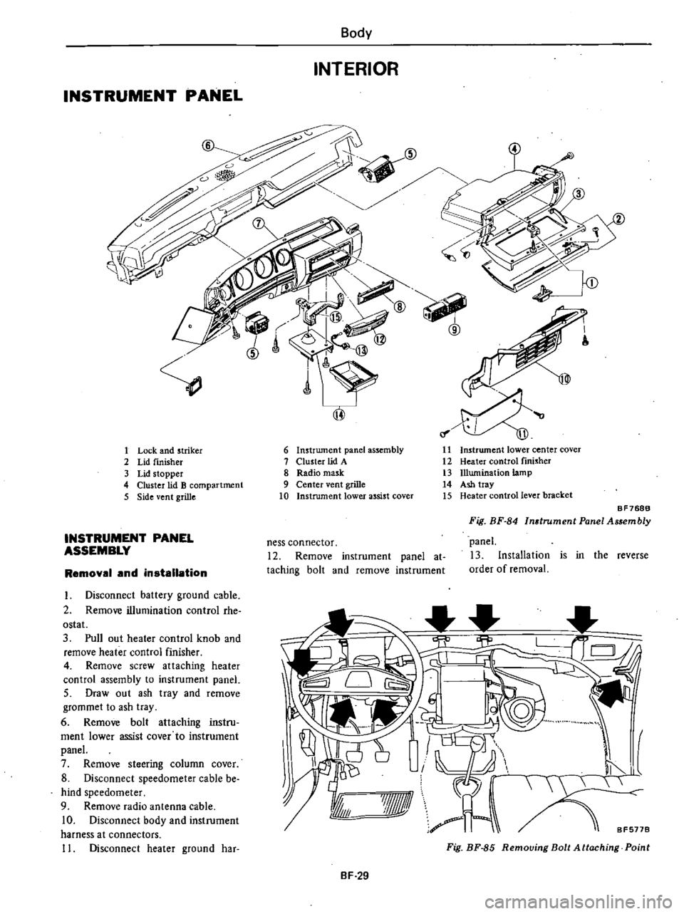
INSTRUMENT
PANEL
Body
INTERIOR
1
Lock
and
striker
2
Lid
fInisher
3
Lid
stopper
4
Cluster
lid
B
compartment
5
Side
vent
grille
INSTRUMENT
PANEL
ASSEMBLY
Removal
and
installation
I
Disconnect
battery
ground
cable
2
Remove
illumination
control
rhe
ostat
3
Pull
out
heater
control
knob
and
remove
heater
control
finisher
4
Remove
screw
attaching
heater
control
assembly
to
instrument
panel
5
Draw
out
ash
tray
and
remove
grommet
to
ash
tray
6
Remove
bolt
attaching
instru
ment
lower
assist
cover
to
instrument
panel
7
Remove
steering
column
cover
8
Disconnect
speedometer
cable
be
hind
speedometer
9
Remove
radio
antenna
cable
10
Disconnect
body
and
instrument
harness
at
connectors
11
Disconnect
heater
ground
har
6
Instrument
panel
assembly
7
Cluster
lid
A
8
Radio
mask
9
Center
vent
grille
10
Instrument
lower
assist
cover
11
Instrument
lower
center
cover
12
Heater
control
fInisher
13
Illumination
lamp
14
Ash
tray
15
Heater
control
lever
bracket
ness
connector
12
Remove
instrument
panel
at
taching
bolt
and
remove
instrument
BF768B
Fig
BF
84
Instrument
Panel
Assembly
panel
13
Installation
is
in
the
reverse
order
of
removal
I
I
I
8F5778
7Jf1ll
A
Fig
BF
85
Removing
Bolt
Attaching
Point
BF
29
Page 441 of 548
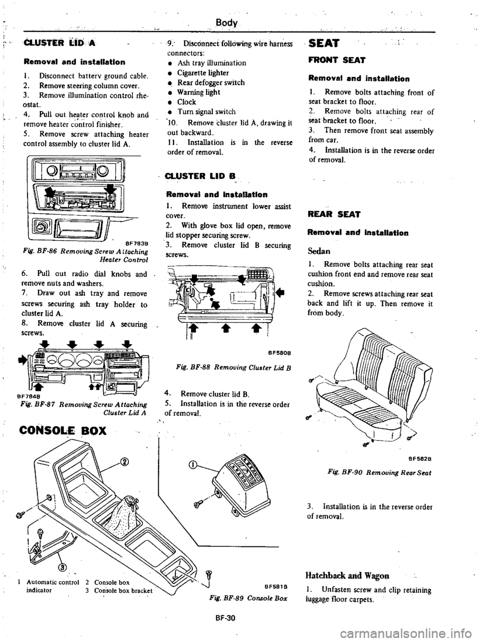
CLUSTER
I
IDA
Removal
and
installation
I
Disconnect
batterv
ground
cable
2
Remove
steering
column
cover
3
Remove
illumination
control
rhe
ostat
4
Pull
out
heater
control
knob
and
remove
heater
c
ntrol
finisher
5
Remove
screw
attaching
heater
control
assembly
to
cluster
lid
A
nQ
lQ
Ii
tl
rffmfLu
O
r
BF783B
Fig
BF
86
Removing
Screw
A
Uoching
Heater
Control
6
Pull
out
radio
dial
knobs
and
remove
nuts
and
washers
7
Draw
out
ash
tray
and
remove
screws
securing
ash
tray
holder
to
cluster
lid
A
B
Remove
cluster
lid
A
securing
screws
1
G808
iS
Ill
1
CJy
BF7848
Fig
BF
87
Remooing
Screw
Attaching
Cluster
Lid
A
CONSOLE
BOX
@
01
Automatic
control
2
Console
box
indicator
3
Console
box
bracket
Body
9
Disconnect
following
wire
harness
connectors
Ash
tray
illumination
Cigarette
lighter
Rear
defogger
switch
Warning
light
Clock
Turn
signal
switch
10
Remove
cluster
lid
A
drawing
it
out
backward
11
Installation
is
in
the
reverse
order
of
removal
CLUSTER
LID
B
Removal
and
Installation
I
Remove
instrument
lower
assist
cover
2
With
glove
box
lid
open
remove
lid
stopper
securing
screw
3
Remove
cluster
lid
B
securing
screws
i
i
ll
r
II
I
BF580B
Fig
BF
88
Removing
Cluster
Lid
B
4
Remove
cluster
lid
B
5
Installation
is
in
the
reverse
order
of
removal
J
BF581
B
Fig
BF
89
Console
Bo
SF
30
SEAT
FRONT
SEAT
Removal
and
installation
I
Remove
bolts
attaching
front
of
seat
bracket
to
floor
2
Remove
bolts
attaching
rear
of
seat
bracket
to
floor
3
Then
remove
front
seat
assembly
from
car
4
Installation
is
in
the
reverse
order
of
removal
REAR
SEAT
Removal
and
Installation
Sedan
I
Remove
bolts
attaching
rear
seat
cushion
front
end
and
remove
rear
seat
cushion
2
Remove
screws
attaching
rear
seat
back
and
lift
it
up
Then
remove
it
from
body
f
I
8F5828
Fig
BF
90
Removing
Rear
Seat
3
Installation
is
in
the
reverse
order
of
removaL
Hatchback
and
Wagon
I
Unfasten
screw
and
clip
retaining
luggage
floor
carpets
Page 450 of 548
m
c
n
to
l
l
I
g
iF
0
1
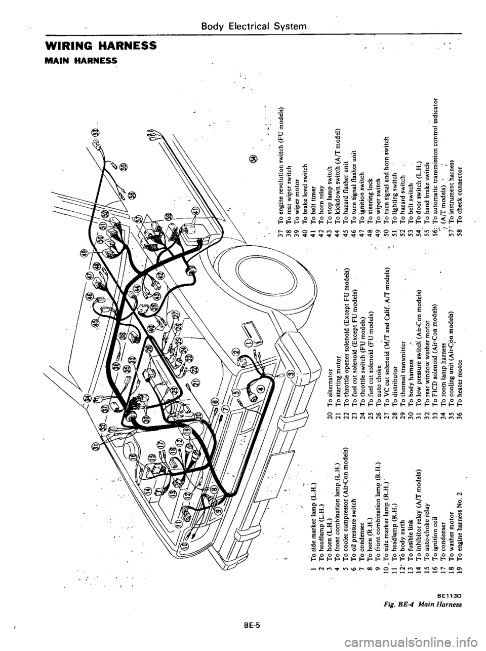
To
side
marker
lamp
L
H
2
To
headlamp
L
H
3
To
horn
L
H
4
To
front
combination
lamp
L
H
5
To
cooler
co
pressor
Air
Con
models
6
To
oil
pressure
switch
7
To
condenser
8
To
horn
R
H
9
To
front
combination
la
t11p
R
H
10
To
side
marker
lamp
R
H
11
To
headlamp
R
H
12
To
body
earth
13
To
fusible
link
14
To
inhibitor
relay
AfT
model
15
To
aut6
choke
relay
16
To
ignition
coil
17
To
condenser
18
To
washer
motor
19
To
engine
harness
No
2
@
20
To
alternator
21
To
starting
motor
22
To
throttle
opener
solenoid
Except
FU
models
23
To
fuel
cut
solenoid
Except
FU
models
24
To
throttle
switch
FU
models
25
To
fuel
cut
solenoid
FU
models
26
To
auto
choke
27
To
VC
cut
solenoid
M
T
and
Calif
AfT
models
28
To
distributor
29
To
thermal
transmitter
30
To
body
harness
31
To
low
pressure
switcn
Air
Con
models
32
To
rear
window
washer
motor
33
To
FICO
solenoid
Air
Con
models
34
To
room
lamp
harness
35
To
cooling
unit
Air
C
on
models
36
To
heater
motor
37
To
engine
revolution
switch
FU
models
38
To
rear
wiper
switch
39
To
wiper
motor
40
To
brake
level
switch
41
To
belt
timer
42
To
horn
relay
43
To
stop
lamp
switch
44
To
kickdown
switch
AfT
model
45
To
hazard
flasher
unit
46
To
turn
signal
flasher
unit
47
To
ignition
switch
48
To
steering
lock
49
To
wiper
switch
50
To
turn
signal
and
hC
rn
switch
51
To
lighting
switch
5i
To
hazard
switch
53
To
belt
switch
54
To
door
switch
L
H
55
To
hand
brake
switch
56
To
automatic
transmission
control
indicator
AfT
models
57
To
instrument
harness
58
To
check
connector
I
0
i
a
z
Z
G
z
tIl
tIl
a
Z
Il
I
to
o
Co
m
16
n
n
OJ
1
3
Page 455 of 548
REMOVAL
AND
INSTALLATION
For
lamp
Note
a
Disconnect
battery
ground
cable
before
starting
to
work
b
To
repJaoe
bull
push
ill
n
bulb
turn
it
counterclockwise
and
re
move
it
from
socket
Install
new
bulb
in
tbe
reverse
order
of
re
moval
9
Removing
bulb
Installing
bulb
BE259C
Fig
BE
9
Replacing
Bulb
c
To
repbce
wedge
base
type
bulb
puD
out
bulb
from
socket
To
inslaD
new
bulb
pusb
bulb
into
socket
Removing
bulb
Installing
bulb
Fig
BE
10
BE260C
R
eplac
ing
Wedge
BlUe
Type
Bulb
Body
Electrical
System
IGNITION
SWITCH
OFF
ICC
01
ST
I
0
0
61
1
ot
Steering
lock
5
I
OUT
I
Iso
16
6
I
T
BEll8D
Fig
BE
II
Ignition
Switch
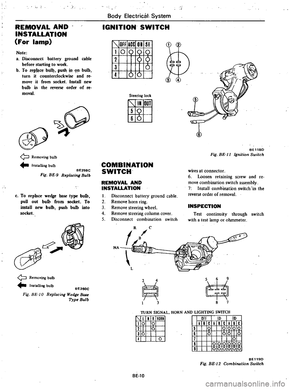
COMBINATION
SWITCH
wires
at
connector
6
Loosen
retaining
screw
and
Ie
move
combination
switch
assembly
7
lnstaD
combination
switch
in
the
reverse
order
of
removal
REMOVAL
AND
INSTALLATION
I
Disconnect
battery
ground
cable
2
Remove
horn
ring
3
Remove
steering
wheel
4
Remove
steering
column
cover
5
Disconnect
combination
switch
INSPECTION
Test
continuity
through
switch
with
a
test
lamp
or
ohmmeter
TURN
SIGNAL
HORN
AND
LIGHTING
SWITCH
1
1
R
HORMI
119
0
I
12
I
6
I
136
I
II
0
I
III
I
F
c
I
c
I
c
15
0
QQOQ
16
6
56
I
5
11
0
II
000Q
10
9
000000
BE119D
Fig
BE
12
Combination
Switch
BE
l0
Page 457 of 548
Body
Electrical
System
ELECTRICAL
UNIT
OF
SIGNAL
SYSTEM
CAUTION
Before
startill1l
to
work
on
any
part
of
electrical
system
disconnect
battery
ground
cable
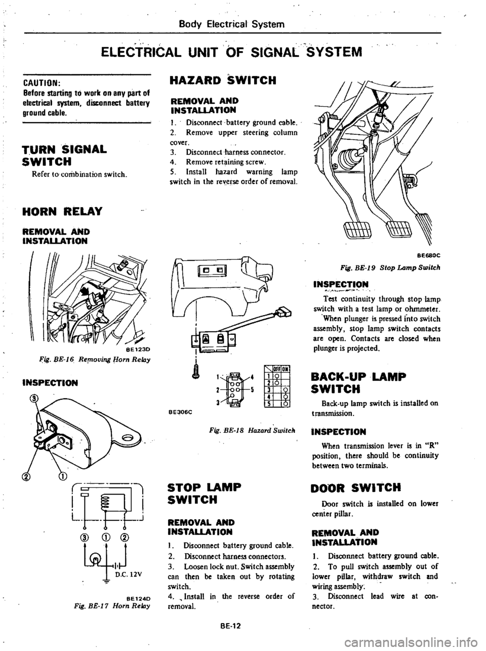
TURN
SIGNAL
SWITCH
Refer
to
combination
switch
HORN
RELAY
REMOVAL
AND
INSTALLATION
I
I
BE123D
Fig
BE
16
ReplOving
om
ReIDy
INSPECTION
1
i
L
l
I
F
I
L
t
r
j
CV
CD
@
pi
101
D
C
12V
BE124D
Fig
BE
17
Horn
ReIDy
HAZARD
SWITCH
REMOVAL
AND
INSTAUATION
I
Disconnect
battery
ground
cable
2
Remove
upper
steering
column
cover
3
Disconnect
harness
connector
4
Remove
ret
ining
screw
5
Install
hazard
warning
lamp
switch
in
the
rev
erse
order
of
removal
i
1
4
2
5
V
lfI
OMI
g
1
t
5
01
BE306C
Fig
BE
IS
Hazard
Switch
STOP
LAMP
SWITCH
REMOVAL
AND
INSTALLATION
I
Disoonnect
battery
ground
cable
2
Disconnect
harness
connectors
3
Loosen
lock
nut
Switch
assembly
can
then
be
taken
out
by
rotating
switch
4
Install
in
the
reverse
order
of
removal
BE
12
BE68QC
Fig
BE
19
Stop
Lamp
Switch
INSPECTION
Test
oontinuity
through
stop
lamp
switch
with
a
test
lamp
or
ohmmeter
When
plunger
is
pressed
into
switch
assembly
stop
lamp
switch
contacts
are
open
Contacts
are
closed
when
plunger
is
projected
BACK
UP
LAMP
SWITCH
Back
up
lamp
switch
is
installed
on
transmission
INSPECTION
When
transmission
lever
is
in
R
position
there
should
be
continuity
between
two
terminals
DOOR
SWITCH
Door
switch
is
installed
on
lower
center
pillar
REMOVAL
AND
INSTAUATION
I
Disconnect
battery
ground
cable
2
To
pull
switch
assembly
out
of
lower
pillar
withdraw
switch
and
wiring
assembly
3
Disconnect
lead
wire
at
con
nector
Page 458 of 548
Body
Electrical
System
INSPECTION
4
Installation
is
in
the
reverse
order
of
removal
Test
continuity
through
door
switch
with
a
test
lamp
or
ohmmeter
When
plunger
is
pressed
into
switch
assembly
door
switch
contacts
are
open
Contacts
are
closed
when
plung
er
is
projected
METERS
AND
GAUGES
3
Remove
steering
column
cover
4
Remove
cluster
lid
A
referring
to
Instrument
Panel
Section
BF
for
reqlOval
and
installation
5
Remove
retaining
screws
6
Disconnect
speedometer
cable
by
pushing
and
turning
connector
cap
counterclockwise
7
Disconnect
lead
wire
terminals
for
multi
pole
connector
and
tachome
ter
if
so
equipped
8
Install
combination
meter
in
the
reverse
order
of
removal
CAUTION
Before
starting
to
work
on
any
part
of
electrical
sYstem
disconnect
battery
ground
cable
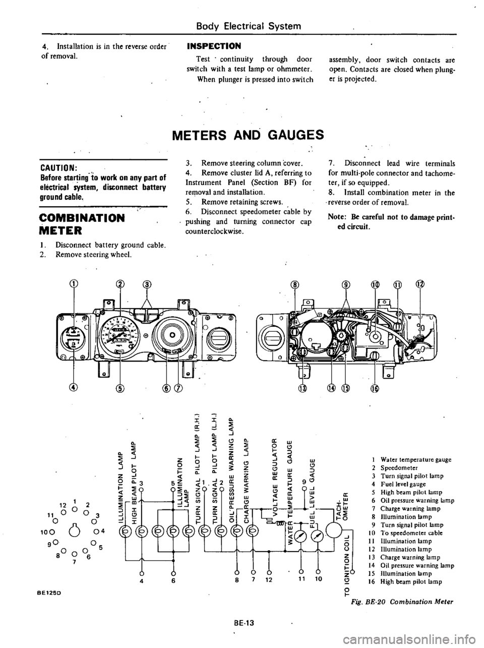
COMBINATION
METER
Note
Be
careful
not
to
damage
print
ed
circuit
I
Disconnect
battery
ground
cable
2
Remove
steering
wheel
CD
Cl
B
i
lJ
Q
@
8
0
I
0
w
@
@
I
Q
a
d
Q
Q
J
Q
2
Cl
0
a
w
Q
3
j
J
Z
t
0
J
W
C
I
0
9
J
CI
C
CI
J
0
I
Q
a
Cl
w
z
J
w
Z
a
c
o
0
3
S2
J1
J2
a
a
l
gO
C
4
l
w
I
EO
l
c
zO
zO
1
Cl
CjU
z
3
Q
Q
w
c
ffi
ffi
to
J
C
U
en
a
C
a
w
i
r
@
p
g10
l
0
U
lJ
v
v
zO
8
7
12
11
10
Q
o
I
Fig
BE
20
Combination
Meter
1
Water
temperature
gauge
2
Speedometer
3
Turn
signal
pilot
lamp
4
Fuel
level
gauge
5
High
beam
pilot
lamp
6
Oil
pressure
warning
lamp
7
Charge
warning
lamp
8
Illumination
lamp
9
Turn
signal
pilot
lamp
10
To
speedometer
cable
11
Illumination
lamp
12
Illumination
lamp
13
Charge
warning
lamp
14
Oil
pressure
warning
lamp
15
Illumination
lamp
16
High
beam
pilot
lamp
12
1
11
00
o
100
6
gO
80
0
7
2
o
3
o
04
Os
o
6
U
4
u
6
BE125D
BE13
Page 497 of 548
Body
Electrical
System
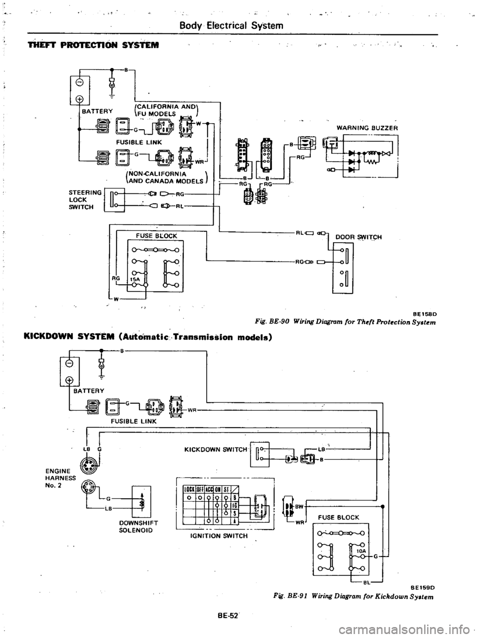
THEFT
CTlON
SYSTEM
t
o
CALIFORNIA
ANO
BATTERY
FU
MOOELS
G
t
WT
FUSIBGLE
LINK
I
at
L
Q
Q
WRJ
NON
cALlFORNIA
ANO
CANAOA
MOOELS
WARNING
BUZZER
STEERING
n
LOCK
u
SWITCH
U
D
7
RC
JQ
RL
2
2
00
i
r
B
Le
r
RljG
8
RG
FUSE
BLOCK
0
RLel
L
OOOR
ITCH
R
CJ
E
W
BEl580
Fig
BE
90
Wiring
Diagram
for
Theft
Protection
Sy
tem
KICKDOWN
SYSTEM
Automatic
Transmission
models
tf
ENGINE
HARNESS
No
2
@
BATTERY
A
G
rT
l
t
1
I
FUSIBLE
LINK
I
I
B
KICKOOWN
SWITCH
rfi
L
1
I
IIIOCI
OIl
ICtOI
Sl
10
009
B
@
I
I
5
li
I
8W
1
Irs
I
0
0
IT
WR
IGNITION
SWITCH
FUSE
BLOCK
OOWNSHIFT
SOLENOIO
0
0
BE1590
Fig
BE
91
Wiring
Diagram
for
Kickdown
Sy
tem
3
C8L
G
BE
52