light DATSUN 210 1979 Manual Online
[x] Cancel search | Manufacturer: DATSUN, Model Year: 1979, Model line: 210, Model: DATSUN 210 1979Pages: 548, PDF Size: 28.66 MB
Page 475 of 548

WIPER
MOTOR
WINDSHIELD
WASHER
MOTOR
REAR
WIPER
MOTOR
REAR
WINDOW
WASHER
MOTOR
m
w
o
HORN
CIGARETTE
LIGHTER
CLOCK
HAZARD
FLASHER
LAMP
STOP
LAMP
ROOM
LAMP
LUGGAGE
ROOM
LAMP
TAIL
LAMP
CLEARANCE
LAMP
LICENSE
PLATE
LAMP
COMBINATION
METER
LAMP
l
I
ll
6
C
l
ii
en
g
0
o
m
till
oill
l
I
t1
l
CO
l
m
l
m
0
z
t
15A
10A
14
fA
20A
16
T
r
t1
l
t1
l
CO
CO
CJ
CJ
1
1
m
m
0
0
z
z
HEATER
lAIR
CONDITIONER
ENGINE
REVOLUTION
SWITCH
FUEL
CUT
SOLENOID
VACUUM
CUT
SOLENOID
AUTO
CHOKE
HEATER
THROTTLE
OPENER
SOLENOID
TURN
SIGNAL
LAMP
GAUGE
I
FUEL
L
WATER
TEMPERATURE
WARNING
LAMP
BRAKE
CHARGE
OIL
PRESSURE
SEAT
BELT
WARNING
BUZZER
BACK
UP
LAMP
KICKDOWN
SOLENOID
TACHOMETER
REAR
DEFOGGER
f
c
It
1
1
m
g
II
n
a
n
c
It
c
1J
c
CIl
z
G
S
3
OJ
o
Cl
m
CD
In
Ql
Page 476 of 548

m
W
ii
I
ll
i
tl
5
3
Cl
l
t
0
HEAOLAMP
R
H
J
HEAOLAMP
IL
H
RB
o
RW
MAIN
HARNESS
8
BATTERY
A
G
Ql
Jj
I
FUSIBLE
LINK
B
R
J
Off
1ST
2ND
TIITe
C
AlBic
RW
Q
QQIQIQ5
1
R
o
0
0
I
0
6
l
I
2
Q
Q
Q
Q
I
a
I
lRB
2
l
2
9
9
9
9
1
ERB
o
B
RW
LIGHTING
SWITCH
I
I
B
I
RW
I
6
OO
00
0
0
Z
en
J
c
m
Z
RW
Z
m
en
en
@
HIGH
BEAM
PILOT
LAMP
COMBINATION
METER
z
11
1
lOG
a
Z
Z
lI
G
It
0
It
II
I
OJ
o
Cl
m
CD
o
Ql
CIl
en
l
3
Page 477 of 548

ii
oil
tl
m
W
Cl
3
r
a
J
en
II
a
i
too
1
l
i
n
l
@
On
I
tJ
1
e
n
m
SlOE
MARKER
LAMP
IR
H
GV
B
S
F
I
n
m
SlOE
MARKER
LAMP
L
H
GW
@
00
00
00
U
gg
GW
0
1iiI
o
T
GW
I
CALIFORNIA
ANO
FU
MOOELS
A
G
U
M
FUSIBLE
LINK
m
Gl
Q
GWR
NON
cALlFORNIA
ANO
CANAOA
MOOELS
I
BATTERY
tG
J
J
RG
I
LIGHTING
SWITCH
FUSE
BLOCK
O
r
0
P
3
J
E
LW
SlOE
MARKER
LAMP
IR
H
An
s
3
I
E
GW
I
S
C
3
n
CJ
g
l
on
0
s
l
m
JJ
ra1
Je
x
s
0
gO
SIDE
MARKER
LAMP
I
L
H
l
i
1
WAGON
SIDE
MARKER
r
LAMP
IR
H
P
Q
JJ
00
00
I
00
GW
TAIL
LAMP
III
R
H
a
3
GW
I
m
8
II
Q
ow
GW
G
t
Jo
OJ
n
z
0
a
Cl
GW
00
I
m
LICENSE
S
CD
LAMP
III
11
1
0
CIl
l
0
s
m
3
0
m
GW
X
8
m
B
TAIL
LAMP
IL
H
JJ
I
UQ
SlOE
MARKER
LAMP
I
L
H
Page 478 of 548

m
W
w
t
e
CALIFORNIA
ANO
BATTERY
FU
MOOELS
g
G
II
V
FUSIBLE
LINK
G
uQ
t
WR
NON
cALlFORNIA
ANO
CANAOA
MOOELS
FUSE
BLOCK
ii
I
ll
l
er
0
er
15A
RG
r
I
W
I
0
0
0
0
tl
ij
a
3
Cl
E
0
too
m
a
f
0
II
OFf
I
IST
2ND
I
IAIBICIAIBlc
liB
C
1
I
101
1
10
10
0
5
11101
116
OI66
I
I
I
I
I
I
6
1
0
I
H
I
101010
2
2
12
8
1161616
LIGHTING
SWITCH
rtt
I
Q
l
B
B
I
I
I
8
00
100
2
2
GW
G
y
jl
I
I
g
fi
GY
GY
Ot
I
GW
RG
GW
T
R
cON
INOICATOR
LAMP
IA
TI
r
H
Jl
L
t1
j
GW
RAOIO
ILLUMINATION
LAMP
IrGW
GI
to
GY
r
l
I
3
I
L
HEATER
CONTROL
PANEL
ILLUMINATION
LAMP
I
GWCJ
lOr
GYO
c
I
ASH
TRAY
ILLUMINATION
CJ
LAMP
CLOCK
H
Gya
3
C3
L
INATION
G
J
J
Y
l
B
I
ILLUMINATION
I
CONTROL
UNIT
G
W
INSTRUMENT
HARNESS
COMBINATION
LAMP
r
r
e
i
o
z
lI
OJ
o
Cl
m
CD
0
Ql
CIl
en
l
3
Page 480 of 548
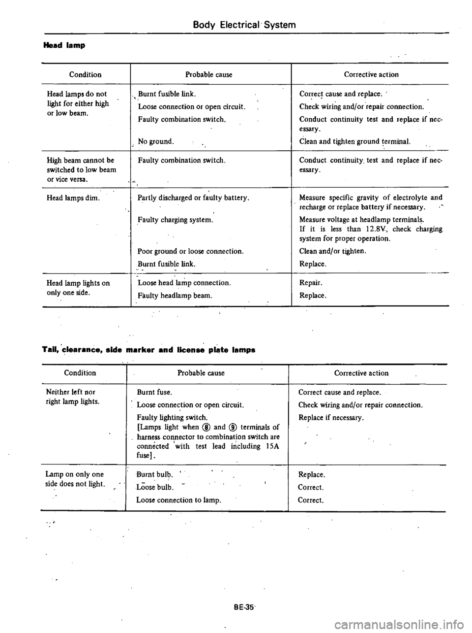
Head
lamp
Condition
Head
lamp
do
not
light
for
either
high
or
low
beam
High
beam
cannot
be
switched
to
low
beam
or
vice
versa
Head
lamps
dim
Head
lamp
lights
on
only
one
side
Body
Electrical
System
Probable
cause
Burnt
fusible
link
Loose
connection
or
open
circuit
Faulty
combination
switch
No
ground
Faulty
combination
switch
Partly
discharged
or
faulty
battery
Faulty
charging
system
Poor
ground
or
loose
connection
Burnt
fusible
link
Loose
head
lamp
connection
Faulty
headlamp
beam
Tail
clearance
aide
marker
and
license
plate
lampa
Condition
Neither
left
nor
right
lamp
lights
Lamp
on
only
one
side
does
not
light
Probable
cause
Burnt
fuse
Loose
connection
or
open
circuit
Faulty
lighting
switch
Lamps
light
when
@
and
@
terminals
of
harness
connector
to
combination
switch
are
connected
with
test
lead
iIlc1uding
15A
fuse
Burnt
bulb
LOose
bulb
Loose
connection
to
lamp
BE
35
Corrective
action
Corree
cause
and
rep1ace
Check
wiring
and
or
repair
connection
Conduct
continuity
test
and
replace
if
nee
essary
Clean
and
tighten
ground
terminal
Conduct
continuity
test
and
replace
if
nee
essary
Measure
specific
gravity
of
electrolyte
and
recharge
or
replace
battery
if
necessary
Measure
voltage
at
headlamp
terminals
If
it
is
less
than
12
8V
check
charging
system
for
proper
operation
Clean
and
or
tighten
Replace
Repair
Replace
Corrective
action
Correct
cause
and
replace
Check
wiring
and
or
repair
connection
Replace
if
necessary
Replace
Correct
Correct
Page 484 of 548
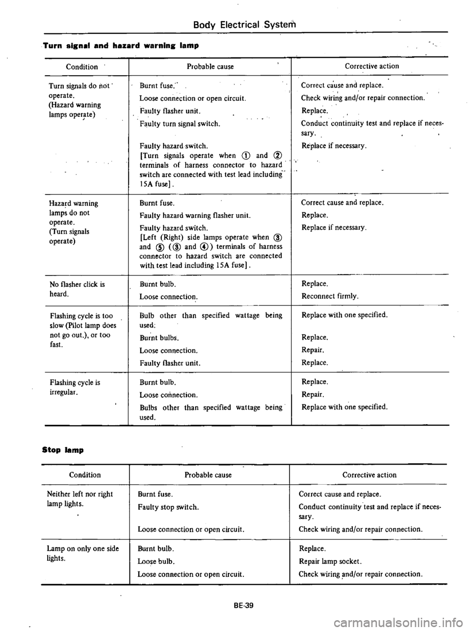
Body
Electrical
System
Turn
signsl
snd
hszsrd
wsrnlng
Ismp
Condition
Turn
signals
do
not
operate
Hazard
warning
lamps
oper
te
Haza
d
warning
lamps
do
not
operate
Turn
signals
operate
No
flasher
click
is
heard
Flashing
cycle
is
too
slow
Pilot
lamp
does
not
go
out
or
too
fast
Flashing
cycle
is
irregular
Stop
Ismp
Condition
Neither
left
nor
right
lamp
lights
Lamp
on
only
one
side
lights
Probable
cause
Burnt
fuse
Loose
connection
or
open
circuit
Faulty
flasher
unit
Faulty
turn
signal
switch
Faulty
hazard
switch
Turn
signals
operate
when
CD
and
i
terminals
of
harness
connector
to
hazard
switch
are
connected
with
test
lead
including
l5A
fuse
Burnt
fuse
Faulty
hazard
warning
flasher
unit
Faulty
hazard
switch
Left
Right
side
lamps
operate
when
@
and
@
@
and
@
terminals
of
harness
connector
to
hazard
switch
are
connected
with
test
lead
including
l5A
fuse
Burnt
bulb
Loose
connection
Bulb
other
than
specified
wattage
being
used
Burnt
bulbs
Loose
connection
Faulty
flasher
unit
Burnt
bulb
Loose
coimection
Bulbs
other
than
specified
wattage
being
used
Probable
cause
Burnt
fuse
Faulty
stop
switch
Loose
connection
or
open
circuit
Burnt
bulb
Loose
bulb
Loose
connection
or
open
circuit
BE
39
Corrective
action
Correct
cause
and
replace
Check
wiring
and
or
repair
connection
Replace
Conduct
continuity
test
and
replace
if
neces
sary
Re
place
if
necessary
Correct
cause
and
replace
Replace
Replace
if
necessary
Replace
Reconnect
firmly
Replace
with
one
specified
Replace
Repair
Replace
Replace
Repair
Replace
with
one
specified
Corrective
action
Correct
cause
and
replace
Conduct
continuity
test
and
replace
if
neces
sary
Check
wiring
and
or
repair
connection
Replace
Repair
lamp
socket
Check
wiring
nd
or
repair
connection
Page 485 of 548
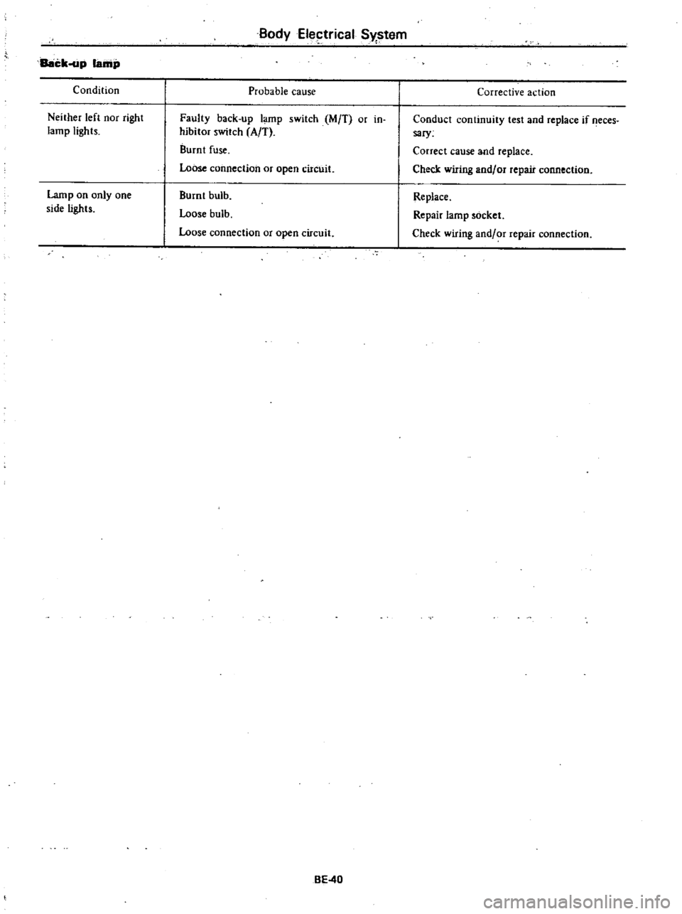
Back
up
lamp
Condition
Neither
left
nor
right
lamp
lights
Lamp
on
only
one
side
lights
Body
Eleptrical
S
I
stem
Probable
cause
Faulty
back
up
lamp
switch
M
T
or
in
hibitor
switch
A
T
Burnt
fuse
Loose
connection
or
open
circuit
Burnt
bulb
Loose
bulb
Loose
connection
or
open
circuit
BE
40
Corrective
action
Conduct
continuity
test
and
replace
if
eces
sary
Correct
cause
and
replace
Check
wiring
andlor
repair
connection
Replace
Repair
lamp
socket
Check
wiring
and
or
repair
connection
Page 491 of 548
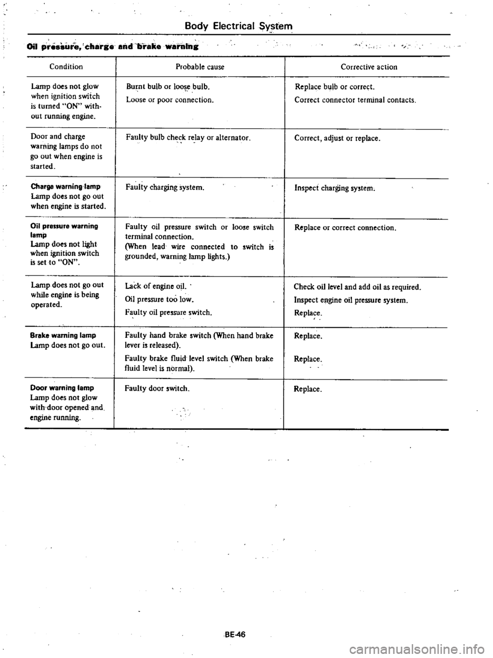
Body
Electrical
Sy
tem
Oil
pr
re
charg
and
brake
warillng
Condition
Lamp
does
not
glow
when
ignition
switch
is
turned
ON
with
out
running
engine
Door
and
charge
warning
lamps
do
not
go
out
when
engine
is
started
Charge
waming
amp
Lamp
does
not
go
out
when
engine
is
started
Oil
pressure
warning
lamp
Lamp
does
not
light
when
ignition
switch
is
set
to
ON
Lamp
does
not
go
out
while
engine
is
being
operated
Brake
warning
lamp
Lamp
does
not
go
out
Door
warning
lamp
Lamp
does
not
glow
with
door
opened
and
engine
running
Probable
cause
Burnt
bulb
or
loo
ebulb
Loose
or
poor
connection
Faully
bulb
check
relay
or
alternator
Faully
charging
system
Faully
oil
pressure
switch
or
loose
switch
terminal
connection
When
lead
wire
connected
to
switch
is
grounded
warning
lamp
lights
Lack
of
engine
oil
Oil
pressure
too
low
Faully
oil
pressure
switch
Faulty
hand
brake
switch
When
hand
brake
lever
is
released
Faully
brake
fluid
level
switch
When
brake
fluid
level
is
normal
Faully
door
switch
BE
46
Corrective
action
Replace
bulb
or
correct
Correct
connector
terminal
contacts
Correct
adjust
or
replace
Inspect
charging
system
Replace
or
correct
connection
Check
oil
level
and
add
oil
as
required
Inspect
engine
oil
pressure
system
Replace
Replace
Replace
Replace
Page 494 of 548
Body
Electrical
System
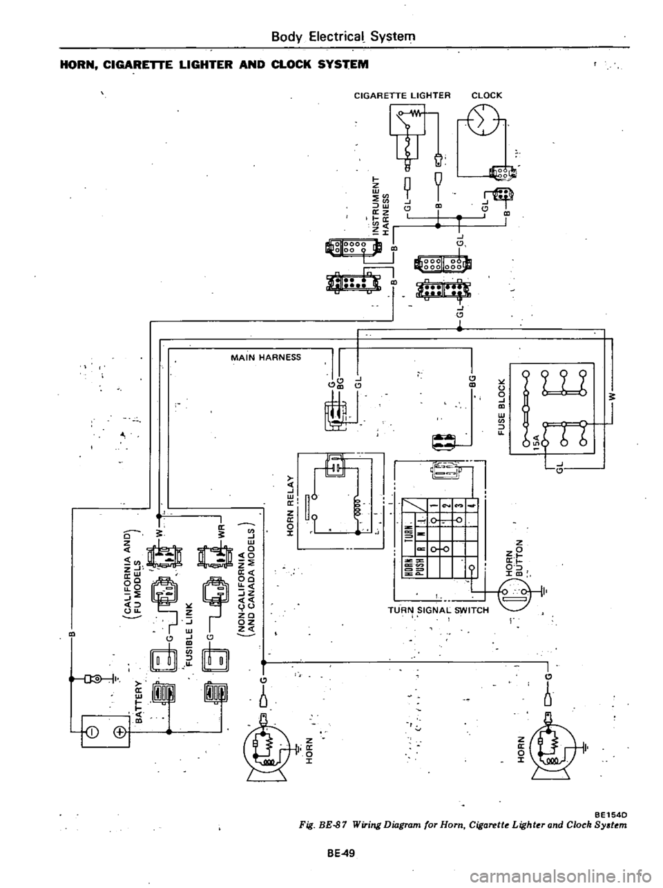
HORN
CIGARETTE
LIGHTER
AND
CLOCK
SYSTEM
I
I
0
W
l
I
fD
CCI
MAIN
HARNESS
I
I
0
en
srb
J
I
U
h
E
0
0
z
t
LL
Z
U
J
w
z
on
QlJ
J
w
0
Y
X
o
I
CIGARETTE
LIGHTER
Itt
9
J
J
I
Z
w
en
l
o
z
1
0
en
Zrl
I
O
tEl
g
r
J
i
I
J
al
I
J
ti
J
ti
1
1
J
J
8ho
f
J1
tf
J
P
II
J
J
1
I
I
e
o
TURN
SIGNAL
SWITCH
CLOCK
01
0
I
J
u
o
J
W
en
u
9W
tutJ
I
j
I
6
I
r
BE154D
Fig
BE
87
Wiring
Diagram
for
Horn
Cigarette
Lighter
and
Clock
System
BE49
Page 495 of 548

m
ii
lil
cIo
00
tl
i
3
Cl
0
m
0
g
fB
Jo
0
0
Ef1
CALIFORNIA
ANO
FU
MOOELS
t
f
G
W
g
dG
I
WR
FUSIBLE
LINK
8
G
uQ
t
WR
NON
cALIFORNIA
AND
CANAOA
MOOELS
J
TORQUE
CONVERTER
C
ao
GY
INOICATOR
LAMP
5
l
1
00
GW
I
BATTERY
CCOHST7
i
lOCK
Off
A
B
OO
C
I
ti
II
v
u
1
WITCH
IGNITION
S
2ND
Oil
lS1
B
C
C
AI8
C
I
5
A
8
I
QIQ
Q
Q
J1
0
0
I
0
6
B
6
0
7
Q
QIQIQ
8
0
0
0
9
O
I
LIGHTING
SWITCH
Z
1
D
Z
m
en
WR
LB
1lRG
GW
INSTRUMENT
HARNESS
j
lO
GW
I
oGW
GY
00
GY
LW
LW
I@o
00
og
B
0
u
B
LW
LB
I
I
0
0
J8
RG
w
1
0
r
O
FUSE
BLOCK
LW
ClO
LW
W
t
WB
1
r
GY
GW
RAOIO
ffi
i
n
In
U
L
J
UJ
J
U
WB
O
W
SPEAKER
OJ
o
Cl
m
CD
C
e
CIl
en
3