clock setting DATSUN 210 1979 Service Manual
[x] Cancel search | Manufacturer: DATSUN, Model Year: 1979, Model line: 210, Model: DATSUN 210 1979Pages: 548, PDF Size: 28.66 MB
Page 221 of 548

DISASSEMBLY
TRANSMISSION
CASE
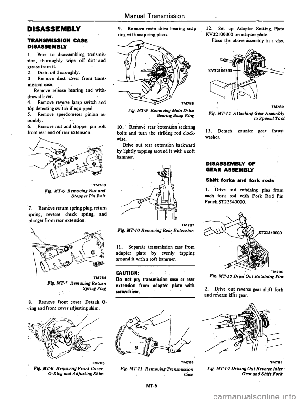
DISASSEMBLY
I
Prior
to
disassembling
traiIsmis
sian
thoroughly
wipe
off
dirt
and
grease
from
it
2
Drain
oil
thoroughly
3
Remove
dust
cover
from
trans
mission
case
Remove
release
bearing
and
with
drawallever
4
Remove
reverse
lamp
switch
and
top
detecting
switch
if
equipped
5
Remove
speedometer
pinion
as
sembly
6
Remove
nut
and
stopper
pin
bolt
from
rear
end
of
rear
extension
TM783
Fig
MT
6
Removing
Nut
and
Stopper
Pin
Bolt
7
Remove
return
spring
plug
return
spring
reverse
check
spring
and
plunger
from
rear
extension
@
@
j
TM784
Fig
MT
7
Rt
moving
Return
Spring
Plug
8
Remove
front
cover
Detach
0
ring
and
front
cover
adjusting
shim
TM785
Fig
MT
B
Removing
Front
Cover
a
Ring
and
Adju
ting
Shim
Manual
Transmission
9
Remove
main
drive
bearing
snap
ring
with
snap
ring
pliers
o
TM188
Fig
MT
9
Rt
mouing
Main
Drive
BNring
Snap
Ring
10
Remove
rear
extenSion
secUring
baits
and
turn
the
striliing
rod
clock
wise
Drive
out
rear
extension
backward
by
lightly
ta
pping
around
it
with
a
soft
hammer
TM787
Fig
MT
10
Removing
Rear
Extemion
11
Separate
transmission
case
from
adapter
plate
by
evenly
tapping
around
it
with
a
soft
hammer
CAUTION
Do
not
pry
transmission
case
or
rear
extension
from
edapter
plate
with
screwdriver
TM788
Fig
MT
II
Removing
Tronsmiuion
COSf
MT
5
12
Set
up
Adapter
Setting
Plate
KV32100300
on
adapter
plate
Place
the
above
assembly
in
a
vise
TM789
Fig
MT
12
A
ttaching
Gear
A
mbly
to
Special
Tool
13
Detach
counter
gear
thrust
washer
DISASSEMBLY
OF
GEAR
ASSEMBLY
Shift
forks
and
fork
rods
I
Drive
out
retaining
pins
from
each
fork
rod
with
Fork
Rod
Pin
Punch
ST23540000
TM790
Fig
MT
13
Drive
Out
Retaining
Pim
2
Drive
out
reverse
gear
shift
fork
and
reverse
idief
gea
TM791
Fig
MT
14
Driving
Out
Re
1dkr
Gear
and
Shift
Fork
Page 230 of 548

Align
notches
in
reverse
3rd
4th
and
1st
2nd
fork
rods
with
check
balls
Note
a
In
the
standard
position
the
upper
surface
of
the
ping
is
nush
with
thaI
of
adapter
plate
b
CheCk
balfpIug
for
i
st
2nd
fork
rod
is
longer
than
those
for
reverse
forkrod
and
3rd
4th
fork
rod
Manual
Transmission
TRANS
SSION
ASSEMBLY
Transmission
case
assembly
Remove
adapter
plale
with
gear
assembly
from
Adapter
Setting
Plate
KV32100300
2
Clean
mating
surfaces
of
adapter
plate
and
transmission
case
Apply
sealant
to
mating
surfaces
of
adapter
plate
3
nd
transmission
case
3
Install
counter
gear
thrust
washer
selected
previously
Note
a
Apply
grease
to
stiding
sorface
of
thrust
washer
b
When
installing
thrust
washer
note
the
front
and
rear
directions
Fig
MT
56
Installing
Check
Ball
0
Plugs
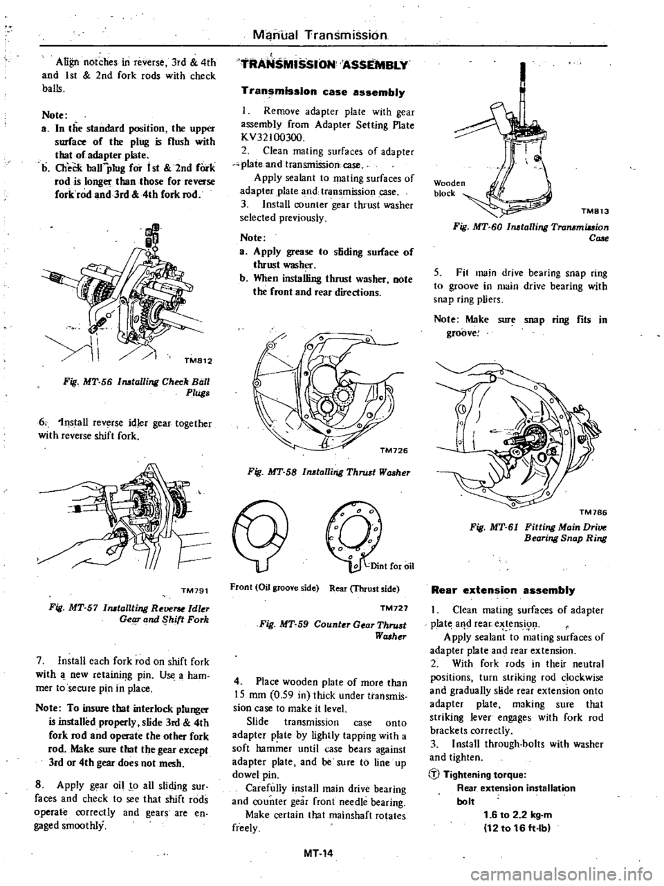
6
1nstall
rev
rse
idler
gear
together
with
reverse
shift
fork
TM791
Fig
MT
57
Installting
Re
ldler
Getg
and
Shift
Fork
7
Install
each
fork
rod
on
shift
fork
with
new
retainif
g
pin
U
a
ham
mer
toseCUfe
pin
in
place
Note
To
insure
that
interlock
plunger
is
installed
properly
slide
3rd
4th
fork
rod
and
operate
the
other
fork
rod
Make
sure
that
the
gear
except
lrd
or
4th
gear
does
not
mesh
8
Apply
g
ar
oil
o
all
sliding
sur
faces
and
check
to
see
that
shift
rods
operate
correctly
and
gears
are
en
gaged
smoothly
Fig
MT
58
Installing
Thrust
Washer
Front
Oil
groove
side
Rear
Thrust
side
TM727
Fig
MT
59
Counter
Gear
Thru
t
Washt
r
4
Place
wooden
plate
of
more
than
15
mm
0
59
in
thick
under
transmis
sion
case
to
make
it
level
Slide
transmission
case
onto
adapter
plate
by
lightly
tapping
with
a
soft
hammer
until
case
bears
against
adapter
plate
and
be
sure
to
line
up
dowel
pin
Carefully
install
main
drive
bearing
and
counter
gear
front
needle
bearing
Make
certain
that
rnainshaft
rotates
freely
MT14
1
Wooden
block
TM813
Fig
MT
60
Installing
Transmiuion
Cale
5
Fit
main
drive
bearing
snap
ring
to
groove
in
main
drive
bearing
with
snap
ring
pliers
Note
Make
sure
snap
ring
fits
in
groove
Fig
MT
61
Fitting
Main
Dri
Bearing
Snap
Ring
Rear
extension
assembly
Clean
mating
surfaces
of
adapter
p
Iat
aIld
rear
e
tens
i91
Apply
sealant
to
mating
surfaces
of
adapter
plate
and
rear
extension
2
With
fork
rods
in
their
neutral
positions
turn
striking
rod
clockwise
and
gradually
slide
rear
extension
onto
adapter
plate
making
sure
that
striking
lever
engages
with
fork
rod
brackets
correctly
3
Install
through
bolts
with
washer
and
tighten
b
Tightening
torque
Rear
extension
installation
bolt
1
6
to
2
2
kg
m
12
to
16
ft
lb
Page 235 of 548

DISASSEMBLY
TRANSMISSION
CASE
DISASSEMBLY
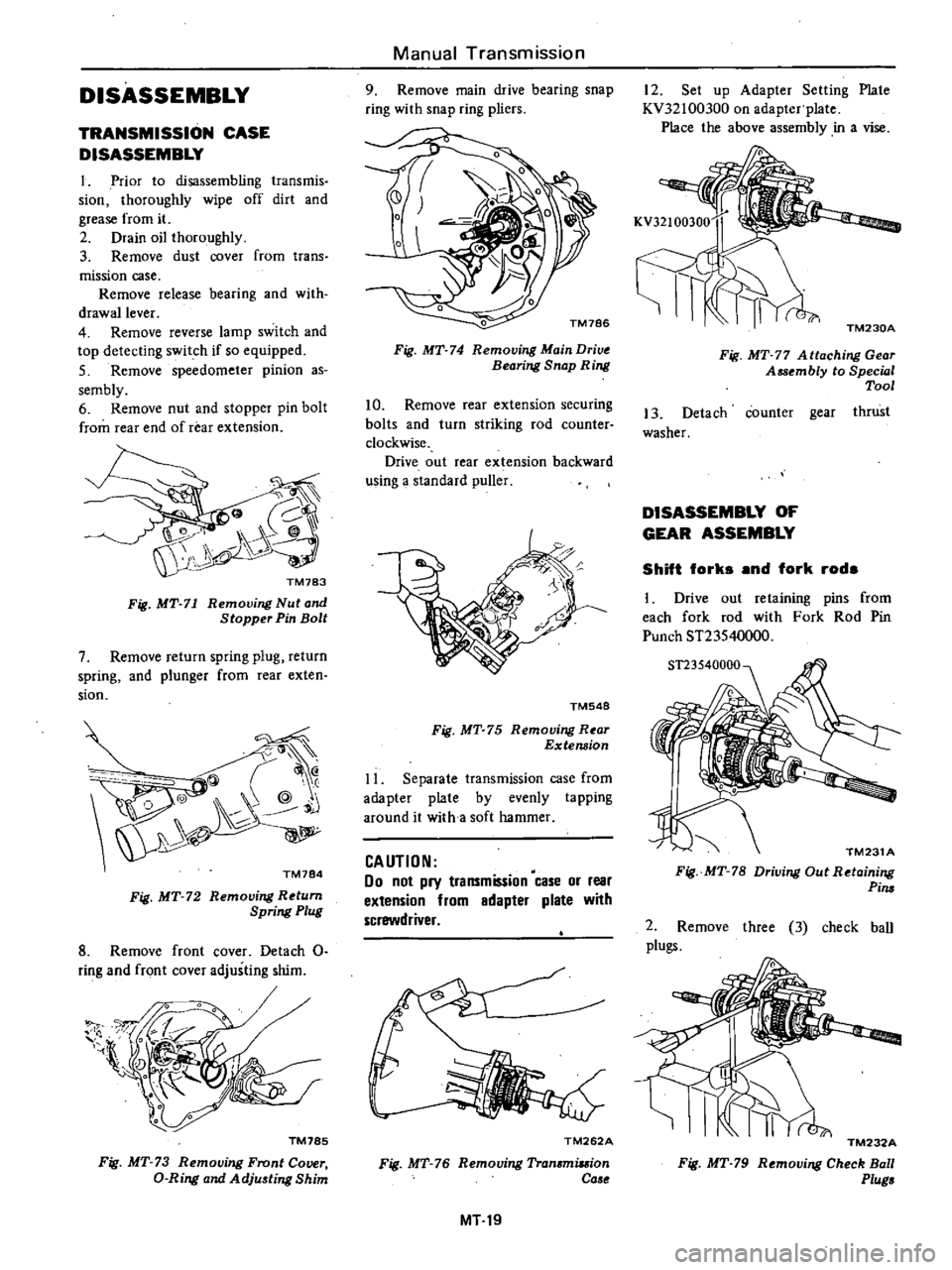
1
Prior
to
disassembling
transmis
sion
thoroughly
wipe
off
dirt
and
grease
from
it
2
Drain
oil
thoroughly
3
Remove
dust
cover
from
trans
mission
case
Remove
release
bearing
and
with
drawallever
4
Remove
reverse
lamp
switch
and
top
detecting
switch
if
so
equipped
5
Remove
speedometer
pinion
as
sembly
6
Remove
nut
and
stopper
pin
bolt
from
rear
end
of
rear
extension
Fig
MT
71
Removing
Nut
and
Stopper
Pin
Bolt
7
Remove
return
spring
plug
return
spring
and
plunger
from
rear
exten
sion
@
@
Q
@
j
TM784
Fig
MT
72
Removing
Return
Spring
Plug
8
Remove
front
cover
Detach
0
ring
and
front
cover
adjusting
shim
1l
l
TM785
Fig
MT
73
Removing
Front
Cover
D
Ring
and
Adju
ting
Shim
Manual
Transmission
9
Remove
main
drive
bearing
snap
ring
with
snap
ring
pliers
Fig
MT
74
Removing
Main
Drive
Bearing
Snap
Ring
10
Remove
rear
extension
securing
bolts
and
turn
striking
rod
counter
clockwise
Drive
out
rear
extension
backward
using
a
standard
puller
TM548
Fig
MT
75
Removing
R
ar
Extension
11
Separate
transmission
case
from
adapter
plate
by
evenly
tapping
around
it
with
a
soft
hammer
CAUTION
00
not
pry
transmission
case
or
rear
extension
from
adapter
plate
with
screwdriver
TM262A
Fig
MT
76
Removing
Tran
miuion
Ca
e
MT19
12
Set
up
Adapter
Setting
Plate
KV32100300
on
adapter
plate
Place
the
above
assembly
in
a
vise
TM230A
Fig
MT
77
A
ttaching
Gear
Assembly
to
Special
Tool
13
Detach
counter
gear
thrust
washer
DISASSEMBLY
OF
GEAR
ASSEMBLY
Shift
forks
and
fork
rods
1
Drive
out
retaining
pins
from
each
fork
rod
with
Fork
Rod
Pin
Punch
ST23540000
TM231
A
Fig
MT
78
Driving
Out
Retaining
Pim
2
Remove
three
3
check
ball
plugs
TM232A
Fig
MT
79
Removing
Check
Ball
Plug
Page 245 of 548

TRANSMISSION
ASSEMBLY
Transmission
case
assembly
r
I
Remove
adapter
plate
with
gear
assembly
from
Adapter
Setting
Plate
KV32100300
2
Clean
mating
surfaces
of
adapter
plate
and
transmission
case
Apply
sealant
to
mating
surfaces
of
adapter
plate
and
transmission
case
3
Install
counter
gear
tluust
washer
selected
previously
Note
a
Apply
grease
to
sliding
surface
of
thrust
washer
b
When
installing
thrust
washer
note
the
front
and
r
ar
directions
Front
Oil
groove
side
Rear
Thrust
side
TM727
Fig
MT
127
Counter
Gear
Thru
t
Wa
her
4
Place
wooden
plate
of
more
than
20
mm
0
79
in
thick
under
transmis
sion
case
to
make
it
level
Slide
transmission
case
onto
adapter
plate
by
lightly
tapping
with
a
soft
hammer
until
case
bears
against
adapter
plate
and
be
sure
to
line
up
dowel
pin
Carefully
install
main
drive
bearing
and
counter
gear
front
needle
bearing
Make
certain
that
mainshaft
rotates
freely
Wooden
block
TM252A
Fig
MT
128
Installing
Transmis
ion
Ca
e
Manual
rransmission
5
Fit
main
drive
bearing
snap
ring
to
groove
in
main
drive
bearing
with
snap
ring
pliers
Note
Make
sure
sno
p
ring
fits
in
groove
Fig
MT
129
Fitting
Main
Drive
flearing
Snap
Ring
ReBr
extension
assembly
I
Clean
I
lating
surfaces
of
adapter
plate
and
rcar
extension
Apply
sealant
to
mating
surfaces
of
adapter
plate
a
itd
rear
extension
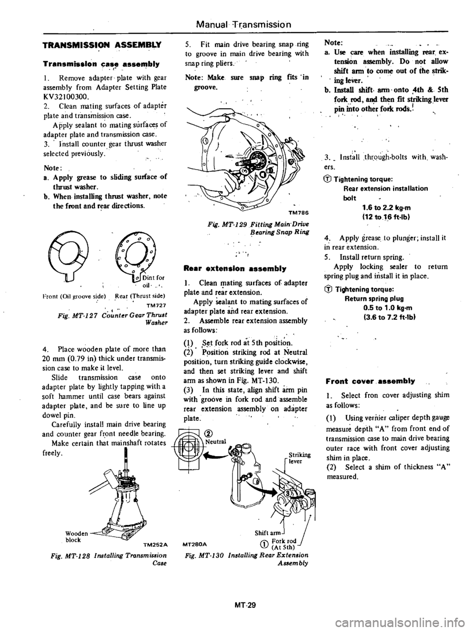
2
Assemble
rear
extension
assembly
as
follows
q
Set
fork
rod
at
5th
position
2
P
sition
striking
rod
at
Neutral
position
turn
striking
guide
clockwise
and
then
set
striking
lever
and
shift
arm
as
shown
in
Fig
MT
130
3
In
this
state
align
shift
arm
pin
with
groove
in
fork
rod
and
assemble
rear
extension
assembly
on
adapter
plate
MT280A
Shift
ann
J
1
Fork
rod
J
At
5th
Installing
Rear
Extension
Assembly
Fig
MT
130
MT29
Note
a
Use
care
when
installing
rear
ex
tension
assembly
Do
not
allow
shift
ann
to
come
out
of
the
strik
ing
leVer
b
Install
shift
ann
onto
4th
5th
fork
rod
and
then
fit
striking
lever
pin
into
oth
r
fork
rods
3
Install
through
bolts
with
wash
ers
GJ
Tightening
torque
Rear
extension
installation
bolt
1
6
to
2
2
kg
m
12
to
16
ft
lb
4
Apply
grease
to
plunger
install
it
in
rear
extension
5
InstaU
return
spring
Apply
locking
sealer
to
return
spring
plug
and
mstall
it
in
place
GJ
Tightening
torque
Return
spring
plug
0
5
to
1
0
kg
m
3
6
to
7
2
ft
lbl
Front
coyer
assembly
I
Select
fron
cover
adjusting
shim
as
follows
I
Using
verruer
caliper
depth
gauge
measure
depth
A
from
front
end
of
transmission
case
to
main
drive
bearing
outer
race
with
front
cover
adjusting
shim
in
place
2
Select
a
shim
of
thickness
A
measured