ECU DATSUN 210 1979 Service Manual
[x] Cancel search | Manufacturer: DATSUN, Model Year: 1979, Model line: 210, Model: DATSUN 210 1979Pages: 548, PDF Size: 28.66 MB
Page 14 of 548
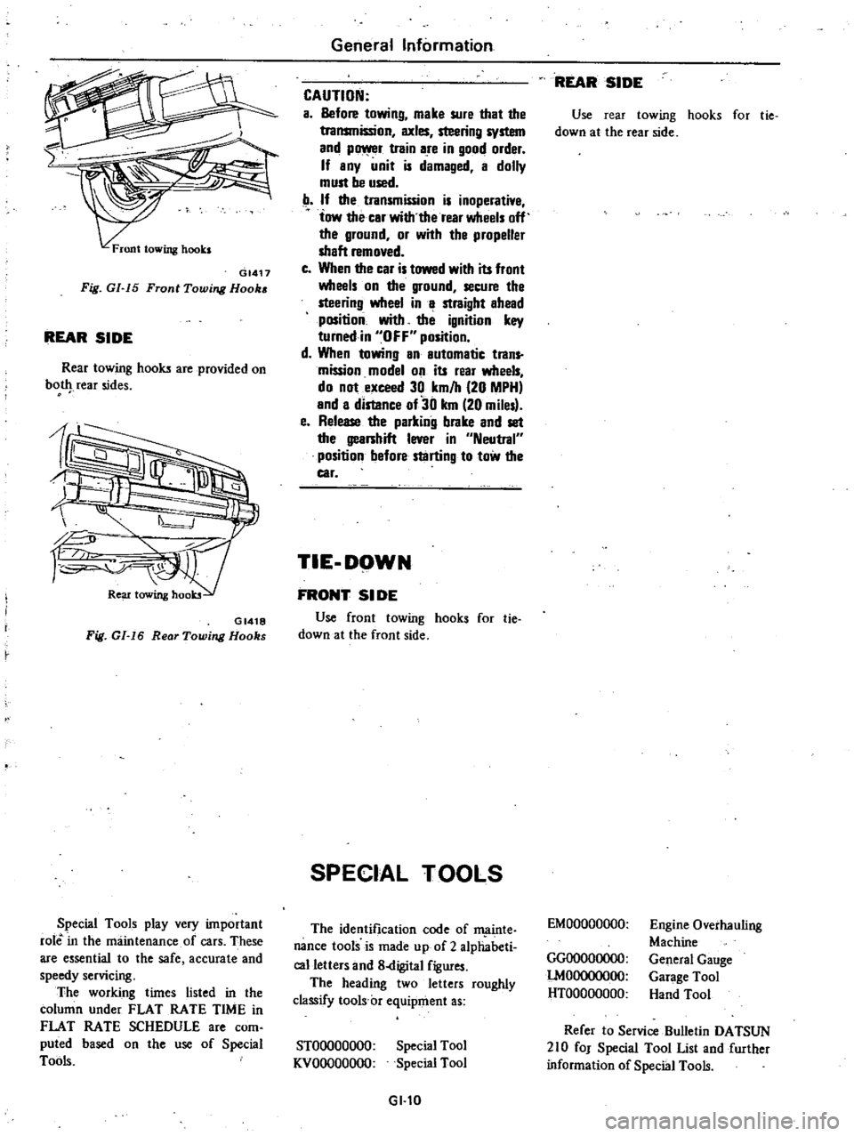
GI417
Fig
GI
15
Front
Towing
Hook
REAR
SIDE
Rear
towing
hooks
are
provided
on
bot
rear
sides
GI418
Fig
GI
16
Rear
Towing
Hooks
Special
Tools
play
very
important
role
in
the
maintenance
of
cars
These
are
essential
to
the
safe
accurate
and
speedy
servicing
The
working
times
listed
in
the
column
under
FLAT
RATE
TIME
in
FLAT
RATE
SCHEDULE
are
com
puted
based
on
the
use
of
Special
Tools
General
Information
CAUTION
a
Before
towing
make
sure
that
the
transmission
axles
steering
system
and
p
r
train
are
in
good
order
If
any
unit
is
damaged
a
dolly
must
be
used
If
the
transmission
is
inoperative
tow
the
car
with
the
rear
wheels
off
the
ground
or
with
the
propeller
shaft
removed
c
When
the
car
is
towed
with
its
front
wheels
on
the
ground
secure
the
steering
wheel
in
a
straight
ahead
position
with
the
ignition
key
turnedin
OFF
position
d
When
towing
an
automatic
trans
mission
model
on
its
rear
wheels
do
not
exceed
30
km
h
20
MPH
and
a
distance
of30
km
20
miles
e
Release
the
parking
brake
and
set
the
gearshift
lever
in
Neutral
position
before
starting
to
tow
the
car
TIE
DOWN
FRONT
51
DE
Use
front
towing
hooks
for
tie
down
at
the
front
side
SPECIAL
TOOLS
The
identification
code
of
ffi
linte
nance
tools
is
made
up
of
2
alphabeti
calletters
and
8
digital
figures
The
heading
two
letters
roughly
classify
tools
c
equipment
as
STOOOOOOOO
KVOOOOOOOO
Special
Tool
Special
Tool
GI
l0
REAR
SIDE
Use
rear
towing
hooks
for
tie
down
at
the
rear
side
EMOOOOOOOO
GGOOOOOOOO
lMOOOOOOOO
HTOOOOOOOO
Engine
Overhauling
Machine
General
Gauge
Garage
Tool
Hand
Tool
Refer
to
Service
Bulletin
DATSUN
210
fOJ
Special
Tool
List
and
further
information
of
Special
Tools
Page 17 of 548
Engine
Tune
up
BASIC
MECHANICAL
SYSTEM
ADJUSTING
INTAKE
AND
EXHAUST
VAL
fE
CLEARANCE
Note
After
tightening
cYlinder
head
bolts
adjust
intake
and
exhaust
valve
clearances
Valve
clearance
ai
ljustment
cannot
be
made
while
the
engine
is
in
opera
tion
To
adjust
proceed
as
follows
I
Start
engine
and
warm
it
up
uritil
water
temperature
indicator
points
to
the
middle
of
gauge
Then
stop
engine
2
Rotate
crankshaft
to
bring
No
I
cylinder
in
top
dead
center
on
its
compression
stroke
3
Remove
valve
rocker
cover
Adjust
valve
clearance
at
following
four
points
while
engine
is
still
hot
CD
Exhaust
valve
of
No
I
cylinder
@
Intake
valve
of
No
I
cylinder
@
Intake
valve
of
No
2
cylinder
@
Exhaust
valve
of
No
3
cylinder
Note
Numbers
in
circle
agree
with
those
in
accompanying
sketch
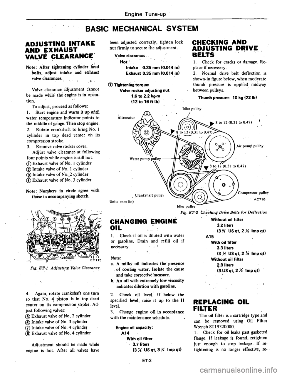
tiri
Fig
ET
1
Adjusting
Value
Clearanu
4
Again
rotate
crankshaft
one
turn
so
that
No
4
piston
is
in
top
dead
center
on
its
ompression
stroke
Ad
just
following
valve
s
CID
Exhaust
valve
of
No
2
cylinder
@
Intake
valve
of
No
3
cylinder
j
Intake
valve
of
No
4
cylinder
@
Exhaust
valve
of
No
4
cylinder
Adjustment
should
be
made
while
engine
is
hot
After
all
valves
have
been
adjusted
correctly
tighten
lock
nut
firmly
to
secure
ihe
adjustment
Valve
clearance
Hot
Intake
0
35
mm
0
014
inl
Exhaust
0
35
mm
0
014
in
tJl
Tightening
torque
Valve
rocker
adjusting
nut
1
6
to
2
2
kltm
12
to
16
ft
lb
Alternator
Crankshaft
pulley
Unit
mm
in
Idler
pulley
Fig
ET
2
CHANGING
ENGINE
OIL
1
Check
if
oil
is
diluted
with
water
or
gasoline
Drain
and
refill
oil
if
necessary
Note
a
A
milky
oil
iiulicates
the
presence
of
cooling
water
Isolate
the
cause
and
take
corrective
measure
b
An
oil
with
extremely
low
viscosity
indicates
dilution
with
gasoline
2
Check
oil
level
If
below
the
specified
level
raise
it
up
to
the
H
level
3
Change
engine
oil
in
accordance
with
the
maintenance
schedule
Engine
oil
capacity
A14
With
oil
filter
3
7
liters
3
U
US
qt
3
Yo
Imp
qtl
ET3
CHECKING
AND
ADJUSTING
DRIVE
BELTS
I
Check
for
cracks
or
damage
Re
place
if
necessary
2
Normal
drive
belt
deflection
is
showndI
figure
below
when
moderate
thumb
pressure
is
applied
midway
between
pulleys
Thumb
pressure
10
kg
221bl
Idler
pulley
Compressor
p1
111ey
AC710
Checking
Drive
Belts
for
Deflection
Without
oil
filter
3
2
liters
3
USqt
2
U
ImP
ltl
A15
With
oil
filter
3
3
liters
3
US
qt
2
U
Imp
qd
Without
oil
filter
2
8
liters
3
us
qt
2
Imp
qd
REPLACING
OIL
FILTER
The
oil
filter
is
a
cartridge
type
and
can
be
removed
using
Oil
Filter
Wrench
STl9320000
I
Check
for
oil
leaks
past
gasketed
Oange
If
leakage
is
found
retighten
just
enough
to
stop
leakage
If
reo
tightening
is
no
longer
effective
re
Page 19 of 548
sion
pressure
chances
are
that
piston
rings
are
worn
or
damaged
2
If
pressure
stays
low
the
likeli
hood
is
that
valve
is
sticking
or
seating
Engine
Tune
up
improperly
3
If
cylinder
compression
in
any
two
adjacent
cylinders
is
low
and
if
adding
oil
does
not
help
the
compres
sion
there
is
leakage
past
the
gasketed
surface
Oil
and
water
in
combustion
cham
bers
can
result
from
this
problem
IGNITION
AND
FUEL
SYSTEM
CHECKING
BATTERY
I
Remove
six
vent
plugs
and
check
electrolyte
level
in
each
battery
cell
If
necessary
pour
distilled
water
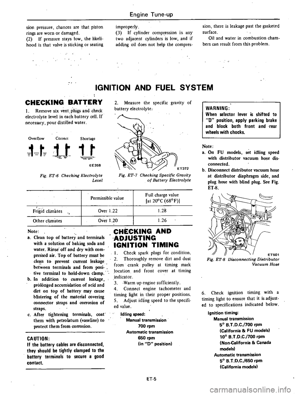
Overflow
Correct
Shortage
t
t
j
t
t
t
EE358
Fig
ET
6
Checking
Electrolyte
Level
2
Measure
the
specific
gravity
of
battery
electrolyte
E
T372
Fig
ET
7
Checking
Specific
Gravity
of
Battery
Electrolyte
Over
1
22
Full
charge
value
at
200C
680F
1
28
1
26
Permissible
value
Frigid
climates
Other
climates
Note
a
Clean
top
of
battery
and
terminals
with
a
solution
of
baking
soda
and
water
Rinse
off
and
dry
with
com
pressed
air
Top
of
battery
must
be
c1
n
to
prevent
current
leakage
between
terminals
and
from
posi
tive
terminal
to
hold
down
clamp
b
In
addition
to
current
leakage
prolonged
accumulation
of
acid
and
dirt
on
top
of
hattery
may
cause
blistering
of
the
material
covering
ronnector
straps
and
rorrosion
of
straps
c
Afte
r
tightening
terminals
coat
them
with
petrolatum
vaseline
to
protect
them
from
corrosion
CAUTION
If
the
battery
cables
are
disconnected
they
should
be
tightly
clamped
to
the
battery
terminals
to
secure
a
good
contact
Over
I
20
CHECKING
AND
ADJUSTING
IGNITION
TIMING
Check
spark
plugs
for
condition
2
Thoroughly
remove
dirt
and
dust
from
crank
pulley
at
timing
mark
location
and
front
cover
at
timing
indicator
3
Warm
up
engine
sufficiently
4
Connect
engine
tachometer
and
timing
light
in
their
proper
positions
5
Adjust
idling
speed
to
the
specifi
ed
value
Idling
speed
Manual
transmission
700
pm
Automatic
transmission
6S0
rpm
in
0
position
ET
S
WARNING
When
selector
lever
is
shifted
to
0
position
apply
parking
brake
and
block
both
front
and
rear
wheels
with
chocks
Note
a
On
FU
models
set
idling
speed
with
distributor
vacuum
hose
dis
connected
b
Disconnect
distributor
vacuum
hose
at
distributor
diaphragm
side
and
plug
hose
with
blind
plug
See
Fig
ET
8
ET501
Fig
ET
B
Disconnecting
Distributor
Vacuum
Hose
6
Check
ignition
timing
with
a
timing
light
to
ensure
that
it
is
adjust
ed
to
specifications
indicated
below
Ignition
timing
Manual
transmission
SO
B
T
0
C
f700
rpm
California
FU
models
100
B
T
0
C
f700
pm
Non
California
Canada
models
Automatic
transmission
SO
B
T
0
C
f6S0
rpm
California
models
Page 24 of 548
make
sure
throttle
valve
operates
click
sound
is
heard
or
continuity
turns
to
OFF
when
engine
speed
decrease
to
idling
If
not
adjust
throttle
valve
switch
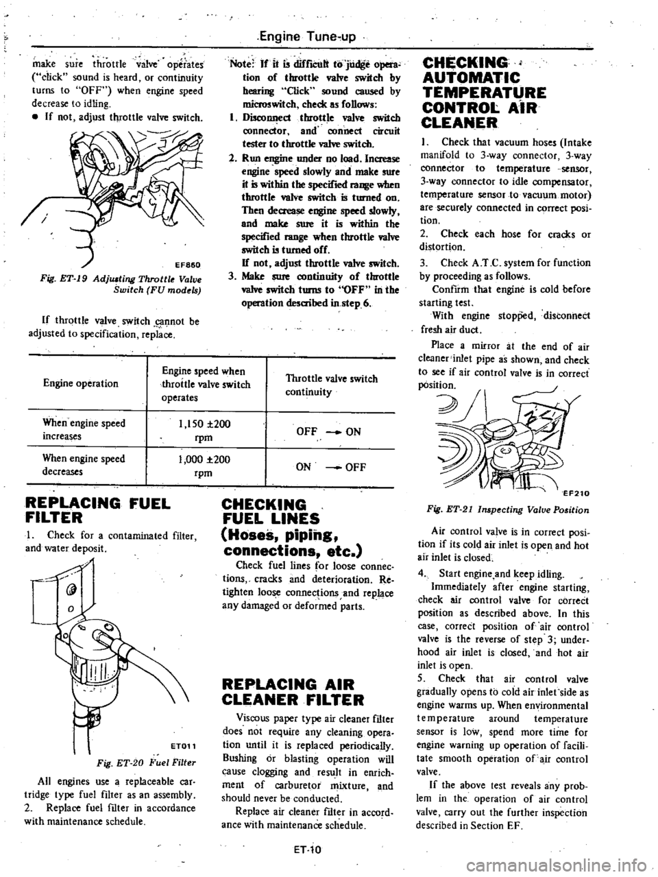
Fig
ET
19
AdjlUting
Throttle
V
ve
Switch
FU
models
If
throttle
valve
switch
g1f1not
be
adjusted
to
specification
replace
Engine
Tune
up
Note
If
it
is
difrlCUlt
to
judge
open
tion
of
throttle
valve
switch
by
hearing
Click
sound
caused
by
microswitch
check
as
follows
1
DiscollI
ecl
throttle
va1ve
switch
ronnector
and
connect
circuit
tester
to
throttle
va1ve
switch
2
Run
engine
under
no
load
Increase
engine
speed
slowly
and
make
sure
it
is
within
the
specified
range
when
throttle
valve
switch
is
turned
on
Then
decrease
engine
speed
slowly
and
make
sure
it
is
within
the
specified
range
when
throttle
va1ve
switch
is
turned
off
If
not
adjust
throttle
valve
switch
3
Make
sure
continuity
of
throttle
vaIve
switch
turns
to
OFF
in
the
operation
desaihed
in
step
6
Engine
operation
Engine
speed
when
throttle
valve
switch
operates
Throttle
valve
switch
continuity
When
engine
speed
increases
1
150
i200
rpm
1
000
1
200
rpm
When
engine
speed
decreases
REPLACING
FUEL
FILTER
I
Check
for
a
contaminated
filter
and
water
deposit
0
9
ET011
Fig
ET
20
Fuel
Filter
All
engines
use
a
replaceable
car
tridge
type
fuel
filter
as
an
assembly
2
Replace
fuel
filter
in
accordance
with
maintenance
schedule
OFF
ON
ON
OFF
CHECKING
FUEL
LINES
Hoses
piping
connections
etc
Check
fuel
lines
for
loose
connec
tions
cracks
and
deterioration
Re
tighten
loose
connections
and
replace
any
damaged
or
deformed
parts
REPLACING
AIR
CLEANER
FILTER
Viscous
paper
type
air
cleaner
filter
does
not
require
any
cleaning
opera
tion
until
it
is
replaced
periodically
Sushing
or
blasting
operation
will
cause
clogging
and
result
in
enrich
ment
of
carburetor
mixture
and
should
never
be
conducted
Replace
air
cleaner
filter
in
accord
ance
with
maintenance
schedule
ET
10
CHECKING
AUTOMATIC
TEMPERATURE
CONTROl
AiR
CLEANER
I
Check
that
vacuum
hoses
Intake
manifold
to
3
way
connector
3
way
connector
to
temperature
sensor
3
way
connector
to
idle
compensator
temperature
sensor
to
vacuum
motor
are
securely
connected
in
C9rrect
posi
tion
2
Check
each
hose
for
cracks
or
distortion
3
Check
A
T
C
system
for
function
by
proceeding
as
follows
ConfIrm
that
engine
is
cold
before
starting
test
With
engine
stopp
d
distonnect
fresh
air
duct
Place
a
mirror
at
the
end
of
air
c1eaner
inlet
pipe
as
shown
and
check
to
see
if
air
control
valve
is
in
correct
pOsition
2J
v
7
EF210
Fig
ET
21
Inspecting
Valve
Position
Air
control
va
ve
is
in
correct
posi
tion
if
its
cold
air
inlet
is
open
and
hot
air
inlet
is
closed
4
Start
engine
and
keep
idling
Immediately
after
engine
starting
check
air
control
valve
for
correCt
position
as
described
above
In
this
case
correct
position
of
air
control
valve
is
the
reverse
of
step
3
under
hood
air
inlet
is
closed
and
hot
air
inlet
is
open
5
Check
that
air
control
valve
gradually
opens
to
cold
air
inlet
side
as
engine
warms
up
When
environmental
temperature
around
temperature
sensor
is
low
spend
more
time
for
engine
warning
up
operation
of
facili
tate
smooth
operation
of
air
control
valve
If
the
above
test
reveals
any
prob
lem
in
the
operation
of
air
control
valve
carry
out
the
further
inspection
described
in
Section
EF
Page 26 of 548
R
EPIACING
AIR
PUMP
AIR
CLEANER
FILTER
Except
FU
models
and
Canada
models
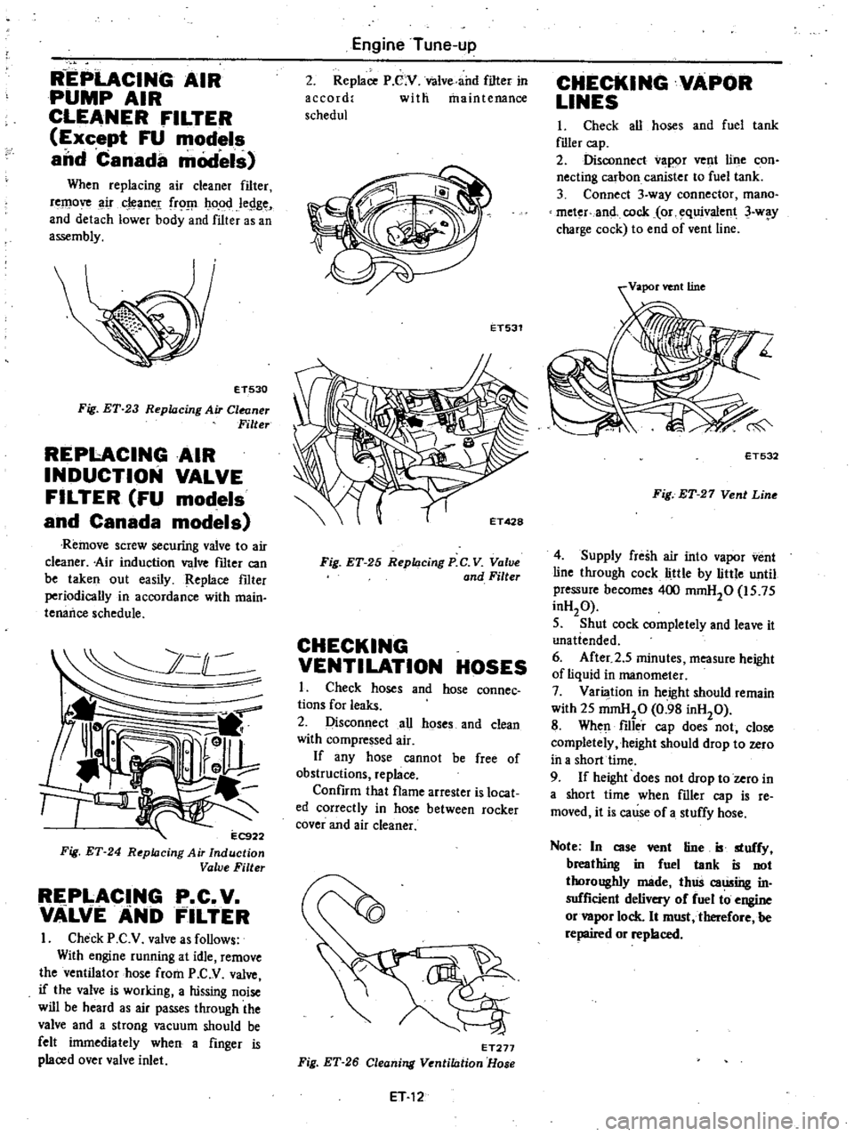
When
replacing
air
cleaner
filter
remove
ir
cleane
frO
ho
od
legge
and
detach
lower
body
and
filter
as
an
assembly
ET530
Fig
ET
23
Replacing
Air
Cleaner
Filter
REPI
ACINGAIR
INDUCTION
VALVE
FILTER
FU
models
and
Canada
models
Remove
screw
securirtg
valve
to
air
cleaner
Air
induction
valve
fIlter
can
be
taken
out
easily
Replace
fIlter
periodically
in
accordance
with
main
tenance
schedule
2
C
l
11
l
r
r
EC9
Fig
ET
24
R
pklcing
Air
Induction
Value
Filter
REPLACING
P
C
V
VALVEANb
FILTER
I
Check
P
C
V
valve
as
follows
With
engine
running
at
idle
remove
the
ventilator
hose
from
P
C
V
valve
if
the
valve
is
working
a
hissing
noise
will
be
heard
as
air
passes
through
the
valve
and
a
strong
vacuum
should
be
felt
inunediately
when
a
finger
is
placed
over
valve
inlet
Engine
Tune
up
2
Replace
P
C
V
Valve
and
filter
in
accord
with
maintenance
schedul
ET531
Fig
ET
25
Replacing
P
C
V
Value
and
Filter
CHECKING
VENTILATION
HOSES
I
Check
hoses
and
hose
connec
tions
for
leaks
2
Disconnect
all
hoses
and
clean
with
compressed
air
If
any
hose
cannot
be
free
of
obstructions
replace
Confirm
that
flame
arrester
is
locat
ed
correctly
in
hose
between
rocker
cover
and
air
cleaner
ET277
Fig
ET
26
Cleaning
Ventilation
Hose
ET
12
CHECKING
VAPOR
LINES
I
Check
all
hoses
and
fuel
tank
flller
cap
2
Disconnect
vapor
vent
line
con
necting
carbon
canister
to
fuel
tank
3
Connect
3
way
connector
mana
meter
and
cock
or
equivalent
3
w
y
charge
cock
to
end
of
vent
line
ET532
Fig
ET
27
Vent
Line
4
Supply
fresh
air
into
vapor
vent
line
through
cock
little
by
little
until
pressure
become
400
mmH20
is
75
inH20
5
Shut
cock
completely
and
leave
it
unatiended
6
After
2
5
minutes
measure
height
of
liquid
in
manometer
7
Varilllion
in
height
should
remain
with
25
mmHp
0
98
inH20
8
When
filler
cap
does
not
close
completely
height
should
drop
to
zero
ih
a
short
time
9
If
height
does
not
drop
to
zero
in
a
short
time
when
filler
cap
is
re
moved
it
is
cause
of
a
stuffy
hose
Note
In
case
vent
tine
B
stuffy
breathing
in
fuel
tank
is
not
thoroughly
made
thlis
caming
in
sufficient
delivery
of
fuel
to
engine
or
vapor
lock
It
must
tberefore
be
repaired
or
replaced
Page 45 of 548
EM303
Fig
EM
31
Checking
Cylinder
Block
Surface
Note
Surface
grinding
6mit
Grinding
limit
of
cylinder
block
is
dependent
upon
cylinder
bead
grinding
of
engjne
Depth
of
cylinder
head
grinding
is
A
Depth
of
cylinder
block
b
1
b
is
U
The
limit
is
A
B
O
imm
0
008
in
The
total
of
A
and
B
should
not
exceed
0
2
mm
0
0079
in
3
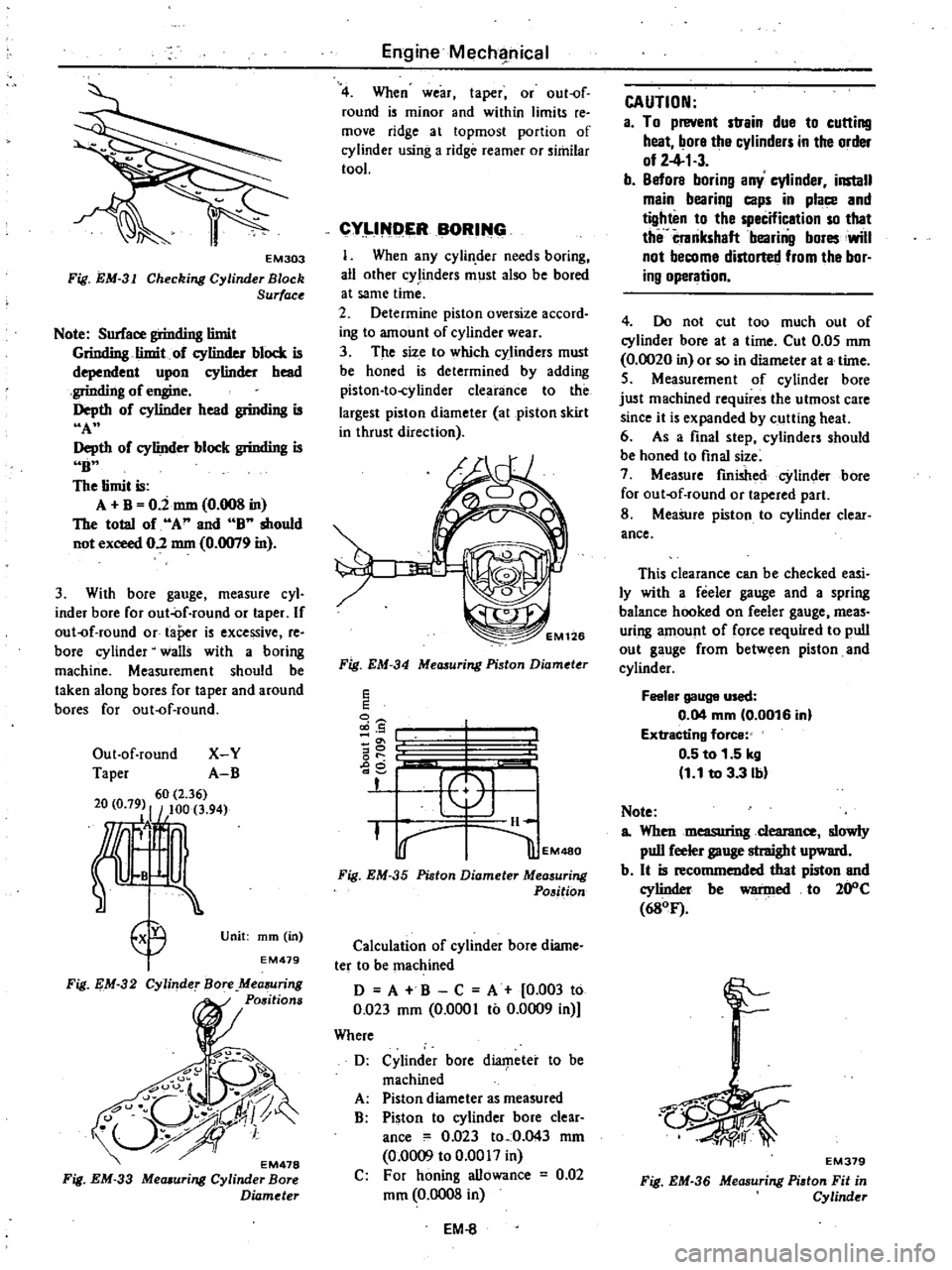
With
bore
gauge
measure
cyl
inder
bore
for
out
of
round
or
taper
If
out
f
round
or
taPer
is
excessive
re
bore
cylinder
walls
with
a
boring
machine
Measurement
should
be
taken
along
bores
for
taper
and
around
bores
for
out
f
round
Out
of
round
X
Y
Taper
A
B
60
2
36
20
0
79
I
100
3
94
Ii
B
E9
I
Unit
mm
in
EM479
Fig
EM
32
Cylinder
Bore
Mea
uring
Positions
EM478
Fig
EM
33
Mecuuring
Cylinder
Bore
Diameter
Engine
Mecha
hical
4
When
wear
taper
or
out
of
round
is
minor
and
within
limits
re
move
ridge
at
topmost
portion
of
cylinder
using
a
ridge
reamer
or
similar
tool
CYLlND
ER
BORING
I
When
any
cylin
der
needs
boring
all
other
cY
linders
must
also
be
bored
at
same
time
2
Determine
piston
oversize
accord
ing
to
amount
of
cylinder
wear
3
The
size
to
which
c
linders
must
be
honed
is
determined
by
adding
piston
to
cylinder
clearance
to
the
largest
piston
diameter
at
piston
skirt
in
thrust
direction
f
EM126
Fig
EM
34
Measuring
Piston
Diameter
E
E
5
g
or
ge
I
PI
H
i
I
lEM480
Fig
EM
35
Piston
Diameter
Measuring
Position
Calculation
of
cylinder
bore
diame
ter
to
be
machined
D
A
B
C
A
0
003
to
0
023
mm
0
0001
to
0
0009
in
Where
D
Cylinder
bore
diaIpeter
to
be
machined
A
Piston
diameter
as
measured
B
Piston
to
cylinder
bore
clear
ance
0
023
to
0
043
mm
0
0009
to
0
0017
in
C
For
honing
allowance
0
02
mm
0
0008
in
EM
8
CAUTION
a
To
prevent
strain
due
to
cutting
heat
bore
the
cylinders
in
the
order
of
2
4
1
3
b
Before
boring
any
cylinder
install
main
bearing
caps
in
place
and
tighten
to
the
specification
so
that
the
crankshaft
bearing
bores
will
not
become
distorted
from
the
bor
ing
operation
4
Do
not
cut
too
much
out
of
cylinder
bore
at
a
time
Cut
0
05
mm
0
0020
in
or
so
in
diameter
at
a
time
5
Measurement
of
cylinder
bore
just
machined
requires
the
utmost
care
since
it
is
expanded
by
cutting
heal
6
As
a
final
step
cylinders
should
be
honed
to
final
size
7
Measure
finished
cylinder
bore
for
out
of
round
or
tapered
part
8
Measure
piston
to
cylinder
clear
ance
This
clearance
can
be
checked
easi
ly
with
a
feeler
gauge
and
a
spring
balance
hooked
on
feeler
gauge
meas
uring
amount
of
force
required
to
pull
out
gauge
from
between
piston
and
cylinder
Feeler
gauge
used
0
04
mm
0
0016
inl
Extracting
force
0
5
to
1
51rg
1
1
to
3
3
b
Note
a
Whenmeasuringcleanmce
slowly
pull
feeler
gauge
straight
upward
b
It
is
recommended
that
piston
and
cylinder
be
warmed
to
20
C
680F
r
EM379
Fig
EM
36
Measuring
Pi
ton
Fit
in
Cylinder
Page 50 of 548
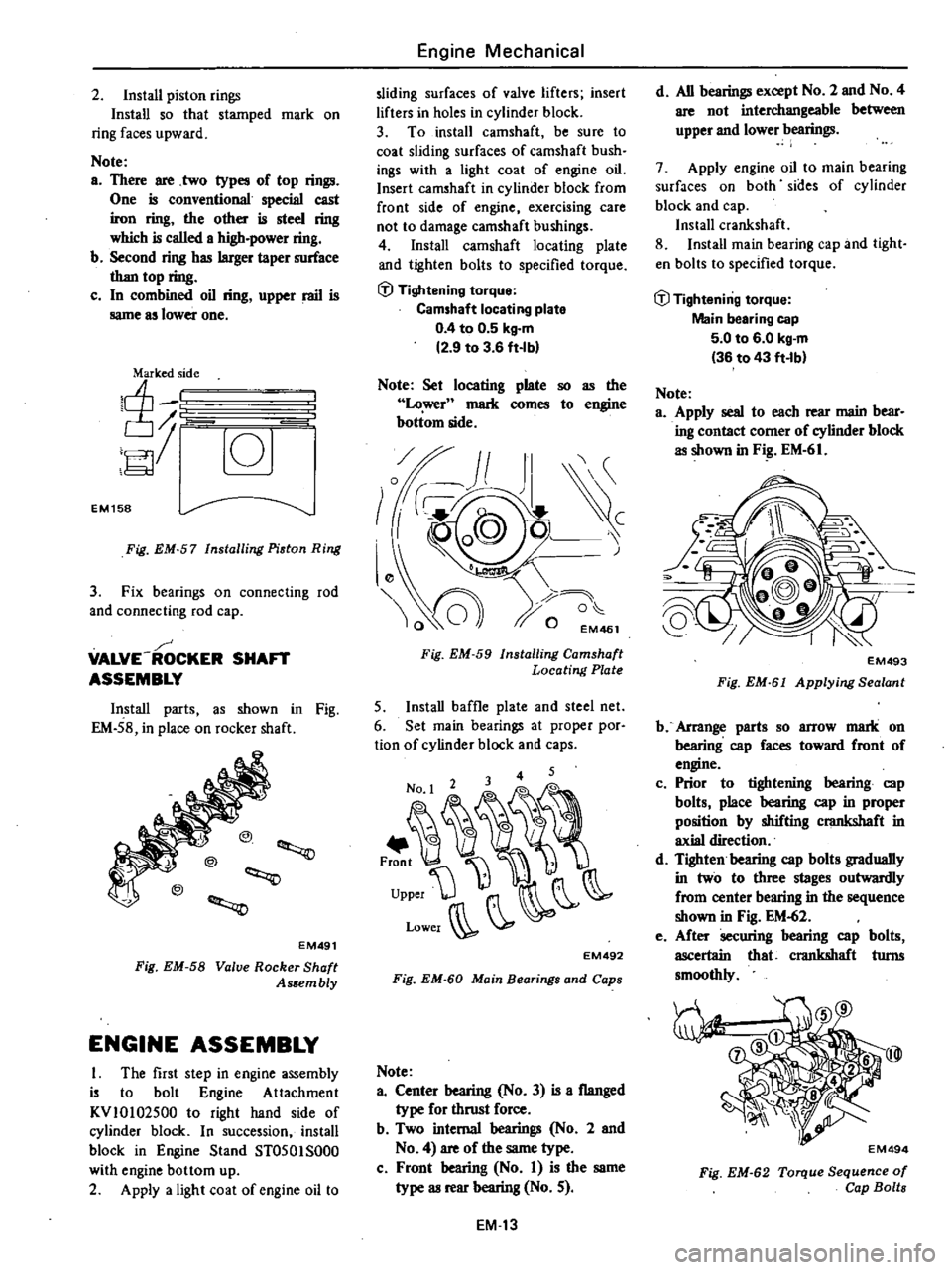
2
Install
piston
rings
Install
so
that
stamped
mark
on
ring
faces
upward
Note
a
There
are
two
types
of
top
rings
One
is
conventional
special
cast
iron
ring
the
other
is
steel
ring
which
is
called
a
high
power
ring
b
Second
ring
has
larger
taper
surface
than
top
ring
c
In
combined
oil
ring
upper
rail
is
same
as
lower
one
I
lnT
10
EM158
Fig
EM
57
Installing
Piston
Ring
3
Fix
bearings
on
connecting
rod
and
connecting
rod
cap
VALVE
ROCKER
SHAFT
ASSEMBLY
Install
parts
as
shown
in
Fig
EM
58
in
place
on
rocker
shaft
@
EM491
Fig
EM
58
Valve
Rocker
Shaft
As
embly
ENGINE
ASSEMBLY
I
The
first
step
in
engine
assembly
is
to
bolt
Engine
Attachment
KV
10
102500
to
right
hand
side
of
cylinder
block
In
succession
install
block
in
Engine
Stand
ST0501S000
with
engine
bottom
up
2
Apply
a
light
coat
of
engine
oil
to
Engine
Mechanical
sliding
surfaces
of
valve
lifters
insert
lifters
in
holes
in
cylinder
block
3
To
install
camshaft
be
sure
to
coat
sliding
surfaces
of
camshaft
bush
ings
with
a
light
coat
of
engine
oil
Insert
camshaft
in
cylinder
block
from
front
side
of
engine
exercising
care
not
to
damage
camshaft
bushings
4
Install
camshaft
locating
plate
and
tighten
bolts
to
specified
torque
i
l
Tightening
torque
Camshaft
locating
plate
0
4
to
0
5
kg
m
2
9
to
3
6
ft
Ibl
Note
Set
locating
plate
so
as
the
Lower
mark
comes
to
engine
bottom
side
Fig
EM
59
Installing
Camshaft
Locating
Plate
5
Install
baffle
plate
and
steel
net
6
Set
main
bearings
at
proper
por
tion
of
cylinder
block
and
caps
No
1
2
3
0
0
0
0
0
0
I
I
J
upperW
r
Lower
J
EM492
Fig
EM
60
Main
Bearings
and
Caps
Note
a
Center
bearing
No
3
is
a
flanged
type
for
thrust
force
b
Two
internal
bearings
No
2
and
No
4
are
of
the
same
type
c
Front
bearing
No
I
is
the
same
type
as
rear
bearing
No
5
EM
13
d
All
bearings
except
No
2
and
No
4
are
not
interchangeable
between
upper
and
lower
bearings
7
Apply
engine
oil
to
main
bearing
surfaces
on
both
sides
of
cylinder
block
and
cap
Install
crankshaft
8
Install
main
bearing
cap
and
tight
en
bolts
to
specified
torque
lil
Tightening
torque
Main
bearing
cap
5
0
to
6
0
kg
m
36
to
43
ft
lb
Note
a
Apply
seal
to
each
rear
main
bear
ing
contact
comer
of
cylinder
block
as
shown
in
F
EM
61
EM493
Fig
EM
6
Applying
Sealant
b
Arrange
parts
so
arrow
mark
on
bearing
cap
faces
toward
front
of
engine
c
Prior
to
tightening
bearing
cap
bolts
place
bearing
cap
in
proper
position
by
shifting
crankshaft
in
axial
direction
d
Tighten
bearing
cap
bolts
gradually
in
two
to
three
stages
outwardly
from
center
bearing
in
the
sequence
shown
in
Fig
EM
62
e
After
securing
bearing
cap
bolts
ascertain
that
crankshaft
turns
smoothly
@I
EM494
Fig
EM
62
Torque
Sequence
of
Cap
Bolts
Page 67 of 548

t
IGHTENING
TORQUE
Cylinder
head
bolt
Rocker
shaft
bracket
bolt
ain
bearing
cap
bolt
Flywheel
fixing
bolt
Drive
plate
fixing
bolt
Al4
AlS
Connecting
rod
cap
nut
Camshaft
sprocket
bolt
Locating
plate
bolt
Valve
rocker
adjusting
nut
Oil
strainer
bolt
Oil
pan
bolt
Oil
pan
drain
plug
Timing
chain
cover
bolt
Crank
pulley
bolt
Water
pump
bolt
Fuel
pump
bolt
Spark
plug
Engine
mounting
securing
bolt
Engine
Mechanical
Unit
kg
iii
ft
lb
7
0
to
7
5
51
to
54
2
0t02
5
14to
18
5
0
to
6
0
36
to
43
8
0
to
9
0
58
to
65
8
0
to
9
0
58
to
65
8
5
to
9
5
61
to
69
3
2
to
3
8
23
to
27
4
0
to
4
8
29
to
35
0
5
to
0
8
3
6
to
5
8
1
6
to
2
2
12to
16
0
9
to
I
4
6
5
to
10
1
0
4
to
0
6
2
9
to
4
3
2
0
to
3
0
14
to
22
0
5
to
0
7
3
6
to
5
1
15to
20
l08
to
145
0
9
to
I
4
6
5
to
1O
l
0
9
to
I
4
6
5
to
10
1
1
5
to
2
0
11
to
14
1
9
to
2
5
14to
18
EM
30
Page 75 of 548
OIL
PUMP
The
oil
pump
and
filter
assembly
is
bolted
to
the
right
side
of
the
cylinder
block
and
can
be
removed
with
the
engine
in
pl
c
The
oil
pump
which
is
driven
by
a
gear
on
the
camshaft
has
the
full
flow
element
type
filter
in
stalled
to
the
oil
pump
cover
REMOVAL
I
Place
a
suitable
container
under
oil
pump
2
Remove
three
bolts
attaching
oil
pump
and
filter
assembly
and
with
draw
assembly
3
Separate
oil
filter
from
oil
pump
4
Ciean
off
old
gasket
from
mating
surfaces
i
E
L043
F
EL
2
R
moving
Oil
Pump
Asso
mbly
INSTALLATION
I
Install
oil
filter
to
oil
pump
2
Locate
oil
pump
and
filter
as
sembly
or
cylinder
block
using
a
spacer
and
new
gasket
Secure
with
three
bolts
l
l
Tightening
torque
Oil
pump
securing
bolts
0
9
to
1
4
kg
m
6
5
to
10
1
ft
lbl
3
Check
oil
level
and
add
oil
if
necessary
4
Start
engine
and
check
for
oil
leaks
5
Remove
the
container
Engine
Lubrication
System
DISASSEMBLY
AND
ASSEMBLY
I
Remove
bolt
securing
pump
cover
to
pump
body
Separate
pump
cover
from
pump
body
2
Slide
out
outer
rotor
from
pump
body
3
Remove
oil
pressure
regulator
plug
washer
shim
spring
and
valve
4
Assemble
oil
pump
in
reverse
order
of
disassembly
Note
a
When
placing
oil
pump
in
a
vice
use
extreme
care
not
to
distort
pump
body
and
cover
in
the
jaws
b
Do
not
pull
out
drive
shaft
pin
securing
drive
shaft
and
inner
rotor
Shaft
is
press
fitted
to
rotor
with
the
pin
caulked
EL044
Fig
EL
3
Oil
Pump
l
l
Tightening
torque
Oil
pump
cove
bolt
0
39
to
0
5
2
kltm
2
8
to
3
8
ti
Ib
Regulator
valve
plug
4
0
to
5
0
kltm
29
to
36
ft
bl
INSPECTION
Wash
all
parts
in
cleaning
solvent
and
dry
wiih
compressed
air
I
hispect
pump
body
and
cover
for
cracks
or
excessive
wear
2
Inspect
pump
rotors
for
excessive
wear
3
Check
inner
rotor
shaft
for
looseness
in
pump
body
4
Inspect
regulator
valve
for
wear
or
scoring
5
Check
regulator
spring
to
see
that
it
is
not
worn
on
its
side
or
collapsed
6
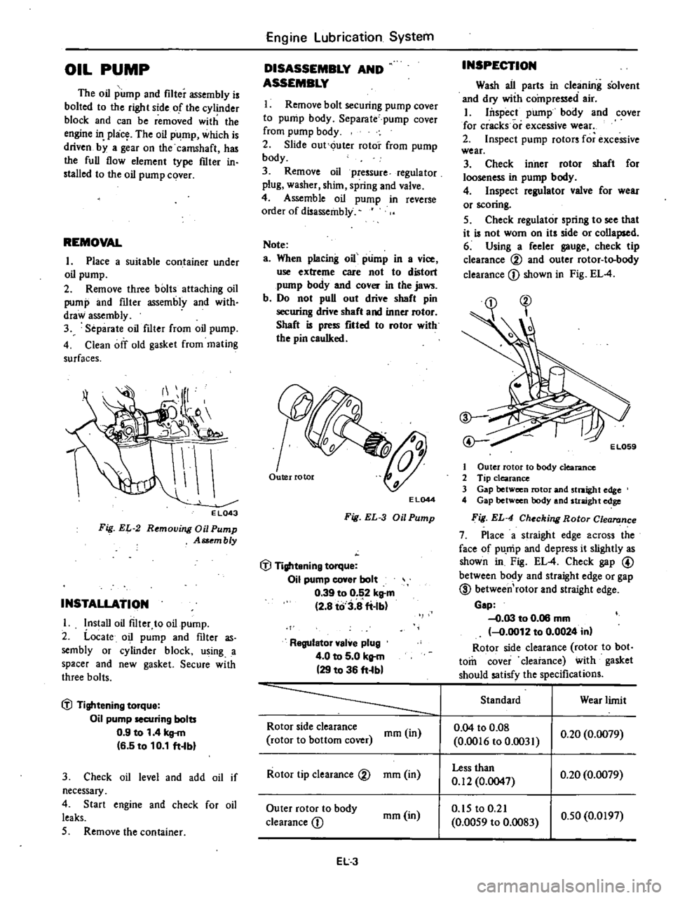
Using
a
feeler
gauge
check
tip
clearance
00
and
outer
rotor
to
body
clearance
CD
shown
in
Fig
EL
4
EL059
1
Outer
rotor
to
body
clearance
2
Tip
clearance
3
Gap
between
rotor
and
stnight
edge
4
Gap
between
body
and
straight
edge
ig
EL
4
Checking
Rotor
Clea
nce
7
Place
a
straight
edge
across
the
face
of
pU
mp
and
depress
it
slightly
as
shown
in
Fig
EL
4
Check
gap
@
between
body
and
straight
edge
or
gap
@
between
rotor
and
straight
edge
Gap
0
03
to
0
06
mm
0
0012
to
0
0024
in
Rotor
side
clearance
rotor
to
bot
tom
cover
clearance
with
gasket
should
satisfy
the
specifications
Standard
Wear
limit
Rotor
side
clearance
mm
in
0
04
to
0
08
rotor
to
bottom
cover
0
0016
to
0
031
0
20
0
0079
Rotor
tip
clearance
V
mm
in
Less
than
0
20
0
0079
0
12
0
0047
Outer
rotor
to
body
mm
in
0
15
to
0
21
0
50
0
0197
clearance
CD
0
0059
to
0
083
EL3
Page 77 of 548

Engine
Lubrication
System
SERVICE
DATA
AND
SPECIFICATIONS
Oil
pump
Standard
Wear
limit
Rotor
side
clearance
nun
in
0
04
to
0
08
0
20
0
0079
Rotor
to
bottom
cover
0
0016
to
0
0031
Rotor
tip
clearance
mm
in
less
than
0
20
0
0079
0
12
0
0047
Outer
rotor
to
body
clearance
nun
in
0
15
to
0
21
0
50
0
0197
0
0059
to
0
0083
Oil
pressure
regulator
valve
Oil
pressure
a
t
idling
Oil
pressure
at
3
000
rpm
Regulator
valve
spring
Free
length
Installed
length
load
kg
cm2
psi
kg
cm2
psi
more
than
0
8
II
3
8
to
5
2
54
to
74
nun
in
nun
kg
in
lb
43
49
I
7122
30
3
3
67
1
193
8
09
Tightening
torque
Oil
pump
securing
bolts
Oil
pump
cover
bolt
Regulator
valve
cap
nut
kg
m
ft
lb
kg
m
ft
lb
kg
m
ft
lb
0
9
to
I
4
6
5
to
10
1
0
39
to
0
52
2
8
to
3
8
4
0
to
5
0
29
to
36
TROUBLE
DIAGNOSES
AND
CORRECTIONS
Condition
Probable
cause
Corrective
action
Oil
leakage
Damaged
or
cracked
body
cover
Oil
leakage
from
gasket
Oil
leakage
from
regulator
valve
Oil
leakage
from
blind
plug
Replace
Replace
Tighten
or
replace
Replace
Decreased
oil
pressure
Leak
of
oil
in
engine
oil
pan
Dirty
oil
strainer
Damaged
or
worn
pump
rotors
Faulty
regulator
Used
of
poor
quality
engine
oil
Correct
Clean
or
replace
Replace
Adjust
or
replace
Replace
Noise
Excessive
backlash
in
pump
rotors
Replace
EL
5