washer fluid DATSUN 210 1979 Service Manual
[x] Cancel search | Manufacturer: DATSUN, Model Year: 1979, Model line: 210, Model: DATSUN 210 1979Pages: 548, PDF Size: 28.66 MB
Page 285 of 548

3
Blowout
piston
by
directing
a
jet
of
air
into
hole
in
clutch
drum
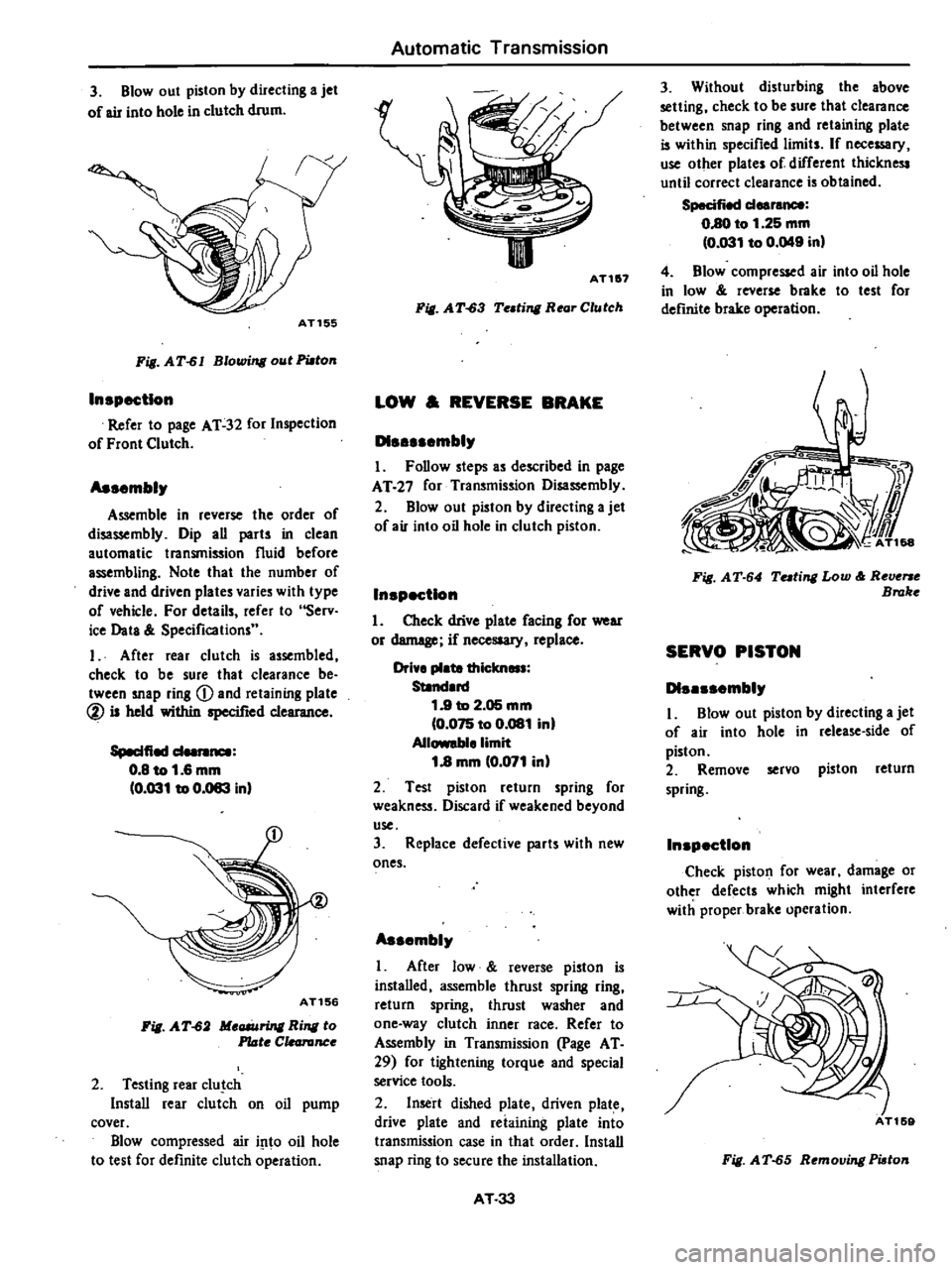
AT155
Fig
AT
61
Blowing
out
PWton
In
pectlon
Refer
to
page
AT
32
for
Inspection
of
Front
Clutch
As
mbly
Assemble
in
reverse
the
order
of
disassembly
Dip
all
parts
in
clean
automatic
transmission
fluid
before
assembling
Note
that
the
number
of
drive
and
driven
plates
varies
with
type
of
vehicle
For
details
refer
to
Serv
ice
Data
Specifications
I
After
rear
clutch
is
assembled
check
to
be
sure
that
clearance
be
tween
snap
ring
Q
and
retaining
plate
@
is
held
within
specified
clearance
Speelfied
d
0
8
to
1
6
mm
0
031
to
0
083
inl
AT156
Fig
AT
62
Meaiuring
Ring
to
Plate
C
canInce
2
Testing
rear
c1u
ch
Install
rear
clutch
on
oil
pump
cover
Blow
compressed
air
i
1to
oil
hole
to
test
for
definite
clutch
operation
Automatic
Transmission
II
AT1
7
Fill
A
T
63
Te
ting
Rear
Clutch
LOW
REVERSE
BRAKE
D1
mbly
I
Follow
steps
as
described
in
page
AT
27
for
Transmission
Disassembly
2
Blowout
piston
by
directing
a
jet
of
air
into
oil
hole
in
clutch
piston
In
pectlon
1
Check
drive
plate
facing
for
wear
or
demege
if
necesaary
replace
Drive
plate
thielm
Standard
1
9
to
2
05
mm
0
075
to
0
081
in
Allowable
limit
1
8
mm
0
071
inl
2
Test
piston
return
spring
for
weakness
Discard
if
weakened
beyond
use
3
Replace
defective
parts
with
new
ones
As
mbly
I
After
low
reverse
piston
is
installed
assemble
thrust
spring
ring
return
spring
thrust
washer
and
one
way
clutch
inner
race
Refer
to
Assembly
in
Transmission
page
AT
29
for
tightening
torque
and
special
service
tools
2
Insert
dished
plate
driven
plate
drive
plate
and
reiaining
plate
into
transmission
case
in
that
order
Install
snap
ring
to
secure
the
installation
AT
33
3
Without
disturbing
the
above
setting
check
to
be
sure
that
clearance
between
snap
ring
and
retaining
plate
is
within
specified
limits
If
nece
ry
use
other
plates
of
different
thickness
until
correct
clearance
is
obtained
Specified
deereM8
0
80
to
1
25
mm
0
031
to
0
049
inl
4
Blow
compressed
air
into
oil
hole
in
low
roverse
brake
to
test
for
deftnite
brake
operation
Fill
AT
64
Tuting
Low
Reverse
Broke
SERVO
PISTON
D1
mbly
I
Blowout
piston
by
dilecting
a
jet
of
air
into
hole
in
release
side
of
piston
2
Remove
servo
piston
return
spring
In
p
ctlon
Check
piston
for
wear
damage
or
other
defects
which
might
interfere
with
proper
brake
opcration
Fig
AT
65
Removing
Piaton
Page 287 of 548

Fig
AT
70
MeG6Uring
Clearonce
Clearance
between
seal
ring
and
ring
groove
Stendard
0
04
to
0
16
mm
10
002
to
0
006
in
I
31earance
Seal
ring
w
I
J
7
r
11
AT1
5
II
Fig
AT
71
MeG6Uring
Clearance
As
mblr
L
Set
up
pump
housing
with
inner
and
outer
pump
gears
on
it
2
Using
Oil
Pump
Assembling
Gauge
ST2SS80001
instan
pump
cover
to
pump
houaing
AT166
Fig
AT
72
Centering
Oil
Pump
3
Temporarily
tighten
pump
secur
ing
bolts
4
Set
the
cunout
of
oil
pump
cover
within
specified
total
indicator
read
ing
Automatic
Transmission
Total
indicator
reading
Lell
than
0
07
mm
10
0028
inl
ST2SSBOOOl
AT264
Fig
AT
73
Me
ring
Runout
S
Tighten
pump
securing
bolts
to
specified
torque
r
Tightening
torque
Oil
pump
housing
to
oil
pump
cover
0
6
to
0
8
kg
m
14
3
to
5
8
ft
Ibl
Note
Be
sure
to
align
con
ter
housini
securing
bolt
holes
6
Again
check
the
runout
of
oil
pump
cover
Note
When
former
Oil
Pump
As
sembling
Gauge
is
to
be
used
make
a
screw
hole
in
side
of
it
PLANETARY
CARRIER
The
planetary
carrier
cannot
be
divided
into
its
individual
components
If
any
part
of
component
is
defec
tive
replace
the
carrier
as
a
unit
In
p
ctlon
Check
clearance
between
pinion
washer
and
planetary
carrier
with
a
feeler
Standard
d
0
20
to
0
70
mm
0
008
to
0
028
in
AT
35
uan
r
J
II
I
AT1S7
Fig
AT
74
MeG6Uring
Pinion
Waaher
to
CanUr
Clearance
Replace
if
over
0
80
mm
0
031
in
CONTROL
VALVE
Tlte
control
valve
assembly
consists
of
many
precision
parts
and
requires
extreme
care
when
it
has
to
be
re
moved
and
serviced
It
is
good
practice
to
place
parts
in
a
part
rack
so
that
they
can
be
reassembled
in
valve
body
in
their
proper
positions
Added
care
should
also
be
exercised
to
prevent
springs
and
other
small
parts
from
being
sca
ttered
and
lost
Before
assembly
dip
all
parts
in
clean
automatic
transmission
fluid
and
check
to
be
certain
that
they
are
free
of
lint
and
other
minute
particles
If
clutch
or
band
is
burnt
or
if
oil
becomes
fouled
the
control
valve
as
sembly
should
be
disassembled
and
flushed
DI
mblr
I
Remove
bolts
and
nuts
which
retain
oil
strainer
Bolts
may
be
re
moved
with
a
screwdriver
but
it
is
recommended
that
Hexagon
Wrench
lIT61000S00
and
Spinner
Handle
lIT623S0000
b
used
Page 463 of 548

CAUTION
a
Be
sure
to
use
only
windshield
washing
solution
Never
mix
soap
powder
or
deter
gent
with
solution
b
To
avoid
improper
windshield
washer
operation
do
not
operate
windshield
washer
continuously
for
more
than
30
seconds
or
without
washer
fluid
Normally
windshield
washer
should
be
operated
for
10
seconds
or
less
at
one
time
Wiper
and
washer
switch
When
removing
wiper
and
washer
switch
remove
combination
switch
Refer
to
Lighting
and
Turn
Signal
Switch
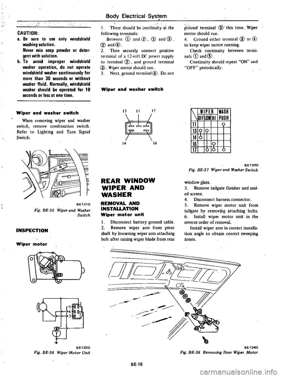
BE131D
Fig
BE
35
Wiper
and
Wll5her
Switch
INSPEctiON
Wiper
motor
W
P
6
LJ
3
B
gu
BE132D
Fig
BE
36
Wiper
Motor
Unit
Body
Electrical
Sys
em
I
There
should
be
continuity
at
the
following
terminals
Between
ill
and
@
@
and
CID
@
and@
2
Then
securely
connect
positive
terminal
of
a
2
volt
DC
power
supply
to
terminal
@
and
ground
terminal
CID
Wiper
motor
should
run
3
Next
ground
terminal@
Do
not
Wiper
and
washer
switch
t3
11
17
I
7b
14
16
REAR
WINDOW
WIPER
AND
WASHER
REMOVAL
AND
INSTALLATION
Wiper
motor
unit
Disconnect
battery
ground
cable
2
Remove
wiper
arm
from
pivot
shaft
by
loosening
wiper
arm
attaching
bolt
after
raising
wiper
blade
from
rear
o
i
Jill
BE1B
ground
terminal
CID
this
time
Wiper
motor
should
run
4
Ground
either
terminal
CID
or
@
to
keep
wiper
motor
running
Chec
k
continuity
between
termi
nals
ill
and@
Continuity
should
repeat
ON
and
OFF
periodically
W
PE
I
WASH
DFF
lOW
HI
PUSH
11
0
116
117
o
g
b
BE1330
Fig
BE
37
Wiper
and
WcuherSwitch
window
glass
3
Remove
tailgate
finisher
and
seal
ed
screen
4
Disconnect
harness
connector
5
Remove
wiper
motor
unit
from
tailgate
by
removiDg
attaching
bolts
6
Install
wiper
motor
unit
in
the
reverse
order
of
removal
Install
wiper
arm
in
correct
installa
tion
angle
to
obtain
correct
sweeping
wQes
BE134D
Fig
BE
38
Removing
Rear
Wiper
Motor
Page 498 of 548

Body
Electrical
System
Condition
Windshield
wiper
and
washer
Probable
cause
Windshield
Motor
wiper
does
not
operate
Windshield
wiper
operat
ing
speed
is
too
slow
Power
supply
and
cable
Switch
Link
Motor
Power
supply
and
cable
Link
Switch
Windshield
Motor
wiper
speed
can
not
be
adjusted
correctly
o
o
fi
5
2
0
E
0
0
Stops
any
where
Does
not
stop
Washer
motor
does
not
operate
when
pushing
washer
switch
on
Washer
motor
operate
bu
t
washer
fluid
is
not
ejected
Motor
Motor
Broken
armature
worn
motor
brush
or
seized
m
tor
shaft
Blown
fuse
Loose
open
or
broken
wiring
Improper
grounding
Improper
switch
contact
Foreign
material
interrupts
movement
of
link
mechanism
Disconnect
link
rod
Seized
or
rusted
arm
shaft
Short
circuit
of
motor
armature
worn
motor
brush
or
seized
motor
snaft
Low
source
voltage
Humming
occurs
on
motor
in
arm
operat
infcycle
due
to
seized
arm
shaft
Improper
switch
contact
Motor
brush
for
either
low
or
high
speed
is
worn
Contaminated
auto
stop
relay
contacts
or
improper
contact
due
to
foreign
matter
Incomplete
auto
stop
operation
Contact
is
not
interrupted
Burnt
fuse
Faulty
switch
Faulty
washer
motor
Loosen
or
poor
connection
contact
at
motor
or
switch
logged
washer
nozzle
BE
53
Corrective
action
Replace
motor
Checkshort
circuit
burnt
component
in
side
motor
or
other
part
for
operation
and
corr
ct
problem
Correct
Correct
I
t
Correct
Correct
Correct
Lubricate
or
replace
arm
shaft
Replace
motor
or
lubricate
bearing
with
engine
oil
Measure
voltage
check
other
electrical
parts
for
operation
and
take
corrective
action
for
power
supply
if
necessary
Lubricate
or
replace
Conduct
continuity
test
and
replace
if
necessary
Replace
motor
Remove
auto
stop
device
cover
and
clean
contacts
carefully
so
as
not
to
deform
relay
plate
Remove
auto
stop
device
cover
and
cor
rect
relay
plate
bending
Correct
cause
and
replace
fuse
Replace
Replace
Repair
Clean
nozzle
or
replace
I