DATSUN B110 1973 Service Manual PDF
Manufacturer: DATSUN, Model Year: 1973, Model line: B110, Model: DATSUN B110 1973Pages: 513, PDF Size: 28.74 MB
Page 61 of 513
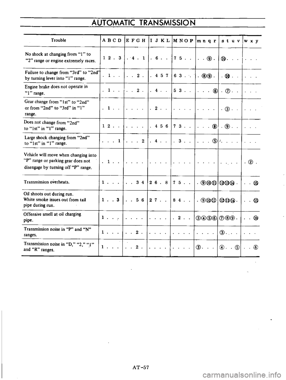
AUTOMATIC
TRANSMISSIO
N
Trouble
IA
BCD
IE
F
G
H
IIJ
K
L
1M
NO
P
1m
n
q
riB
t
u
v
w
x
y
No
shock
at
changing
from
I
to
7
5
@
@
I
1
2
3
4
1
6
I
2
range
or
engine
extremely
races
Failure
to
change
from
3rd
to
2nd
1
2
4
5
7
16
3
I
@@
@
by
turning
lever
into
I
range
Engine
brake
does
not
operate
in
I
2
4
5
3
@
J
I
range
Gear
change
from
1st
to
2nd
or
from
2nd
to
3rd
in
I
I
2
@
range
Does
not
change
from
2nd
1
2
456
7
3
@
@
to
1st
in
I
range
Large
shock
changing
from
2nd
1
2
4
3
IDI
to
1st
in
I
range
Vehicle
will
move
when
changing
into
P
range
or
parking
gear
does
not
1
@
disengage
by
turning
off
P
range
Transmission
overheats
1
3
4
12
6
8
7
5
@@@I@@
@
Oil
shoots
out
during
run
@@@
@@
@
White
smoke
issues
out
from
tail
1
3
5
6
2
7
8
4
pipe
during
run
Offensive
smell
at
oil
charging
11
2
I@
@
ID@I
J
@@
@
pipe
Transmission
noise
in
P
and
N
1
2
I
I@
ranges
Transmission
noise
in
0
2
I
1
2
@
@
@
@
and
R
ranges
AT
57
Page 62 of 513
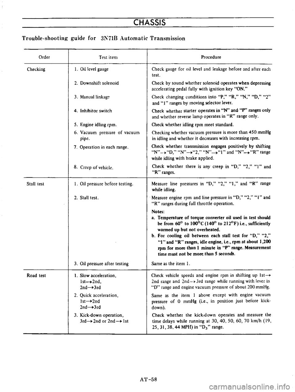
CHASSIS
Trouble
shooting
guide
for
3N71B
Automatic
Transmission
Order
Test
item
Checking
Oil
level
gauge
2
Downshift
solenoid
3
ManuaIlinkage
4
Inhibitor
switch
5
Engine
idling
rpm
6
Vacuum
pressure
of
vacuum
pipe
7
Operation
in
each
range
8
Creep
of
vehicle
Stall
lest
Oil
pressure
before
testing
2
Stall
test
3
Oil
pressure
after
testing
Road
test
Slow
acceleration
Ist
2nd
2nd
3rd
2
Quick
acceleration
Ist
2nd
2nd
3rd
3
Kick
down
operation
3rd
2nd
or
2nd
1st
Procedure
Check
gauge
for
oil
level
and
leakage
before
and
after
each
test
Check
by
sound
whether
solenoid
operates
when
depressing
accelerating
pedal
fully
with
ignition
key
ON
Check
changing
conditions
into
P
R
N
D
2
and
I
ranges
by
moving
selector
lever
Check
whether
starter
operates
in
N
and
tp
ranges
only
and
whether
reverse
lamp
operates
in
R
range
only
Check
whether
idling
rpm
meet
standard
Checking
whether
vacuum
pressure
is
more
than
450
mmHg
in
idling
and
whether
it
decreases
with
increasing
rpm
Check
whether
transmission
engages
positively
by
shifting
N
o
D
N
2
N
I
and
N
R
range
while
idling
with
brake
applied
Check
whether
there
is
any
creep
in
D
2
I
and
R
ranges
2
1
and
R
range
Measure
line
pressures
in
D
while
idling
Measure
engine
rpm
and
line
pressure
in
D
2
I
and
R
ranges
during
fullthrallIe
operation
Notes
a
Temperature
of
torque
converter
oil
used
in
test
should
be
from
600
to
lOOoC
1400
to
2120F
i
e
sufficiently
warmed
up
but
not
overheated
b
For
cooling
oil
between
each
stall
test
for
D
2
1
and
R
ranges
idle
engine
i
e
rpm
at
about
1
200
rpm
for
more
than
1
minute
in
P
range
Measurement
time
must
not
be
more
than
5
secon
Same
as
the
item
I
Check
vehicle
speeds
and
engine
rpm
in
shifting
up
1st
2nd
range
and
2nd
J
3rd
range
while
running
with
lever
in
D
range
and
engine
vacuum
pressure
of
about
200
mmHg
Same
as
the
item
1
above
except
with
engine
vacuum
pressure
of
0
mmHg
i
e
in
position
just
before
kick
down
Check
whether
the
kick
down
operates
and
measure
the
time
delays
while
running
at
30
40
50
60
70
km
h
19
25
31
38
44
MPH
in
D
range
AT
58
Page 63 of 513
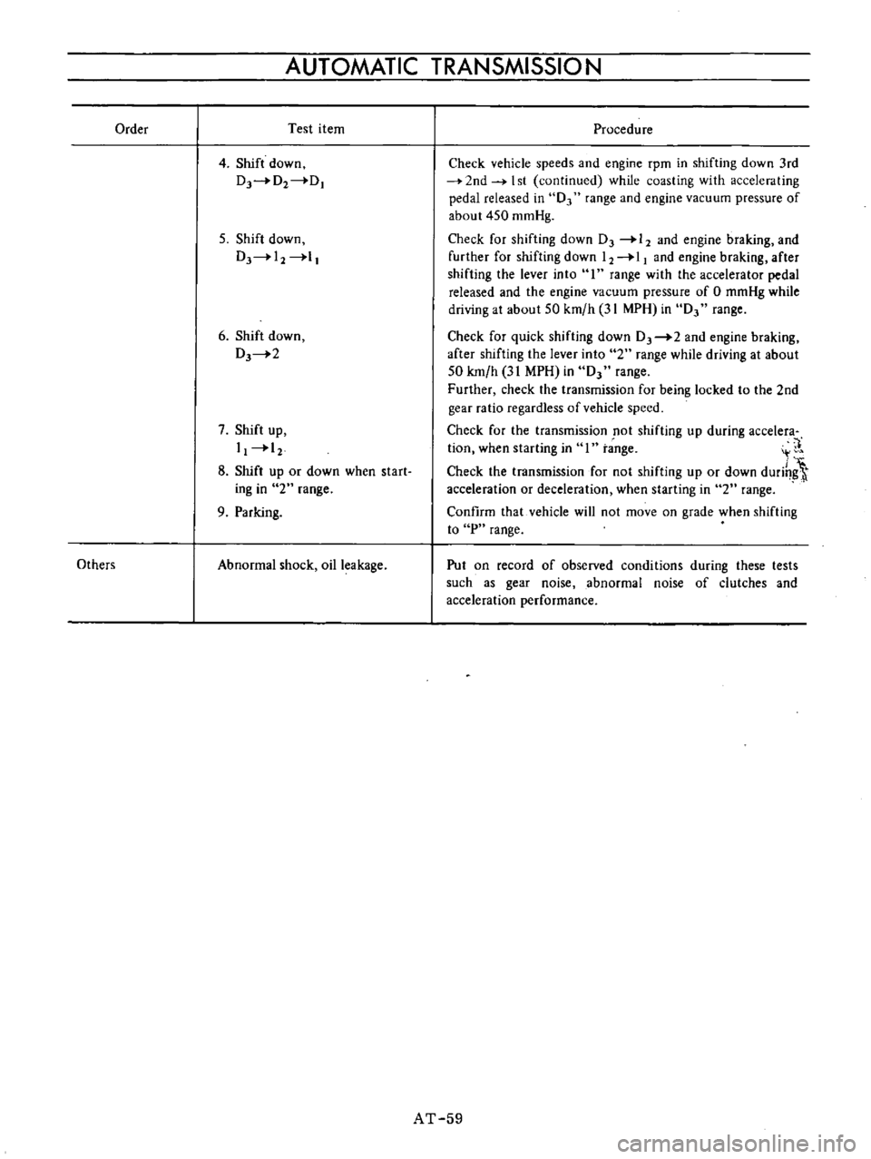
Order
Others
AUTOMATIC
TRANSMISSION
Test
item
4
Shift
down
Dr4D2
DI
5
Shift
down
DJ
I2
l
6
Shift
down
DJ
2
7
Shift
up
I
12
8
Shift
up
or
down
when
start
ing
in
2
range
9
Parking
Abnormal
shock
oil
leakage
Procedure
Check
vehicle
speeds
and
engine
rpm
in
shifting
down
3rd
2nd
I
st
continued
while
coasting
with
acceleraling
pedal
released
in
0
range
and
engine
vacuum
pressure
of
about
450
mmHg
Check
for
shifting
down
DJ
12
and
engine
braking
and
further
for
shifting
down
12
11
and
engine
braking
after
shifting
the
lever
into
I
range
with
the
accelerator
pedal
released
and
the
engine
vacuum
pressure
of
0
mmHg
while
driving
at
about
SO
km
h
31
MPH
in
DJ
range
Check
for
quick
shifting
down
DJ
2
and
engine
braking
after
shifting
the
lever
into
2
range
while
driving
at
about
50
km
h
31
MPH
in
DJ
range
Further
check
the
transmission
for
being
locked
to
the
2nd
gear
ratio
regardless
of
vehicle
speed
Check
for
the
transmission
not
shifting
up
during
acceIera
tion
when
starting
in
1
t
nge
It
Check
the
transmission
for
not
shifting
up
or
down
durih
t
acceleration
or
deceleration
when
starting
in
2
range
Confirm
that
vehicle
will
not
move
on
grade
when
shifting
to
P
range
Put
on
record
of
observed
conditions
during
these
tests
such
as
gear
noise
abnormal
noise
of
clutches
and
acceleration
performance
AT
59
Page 64 of 513
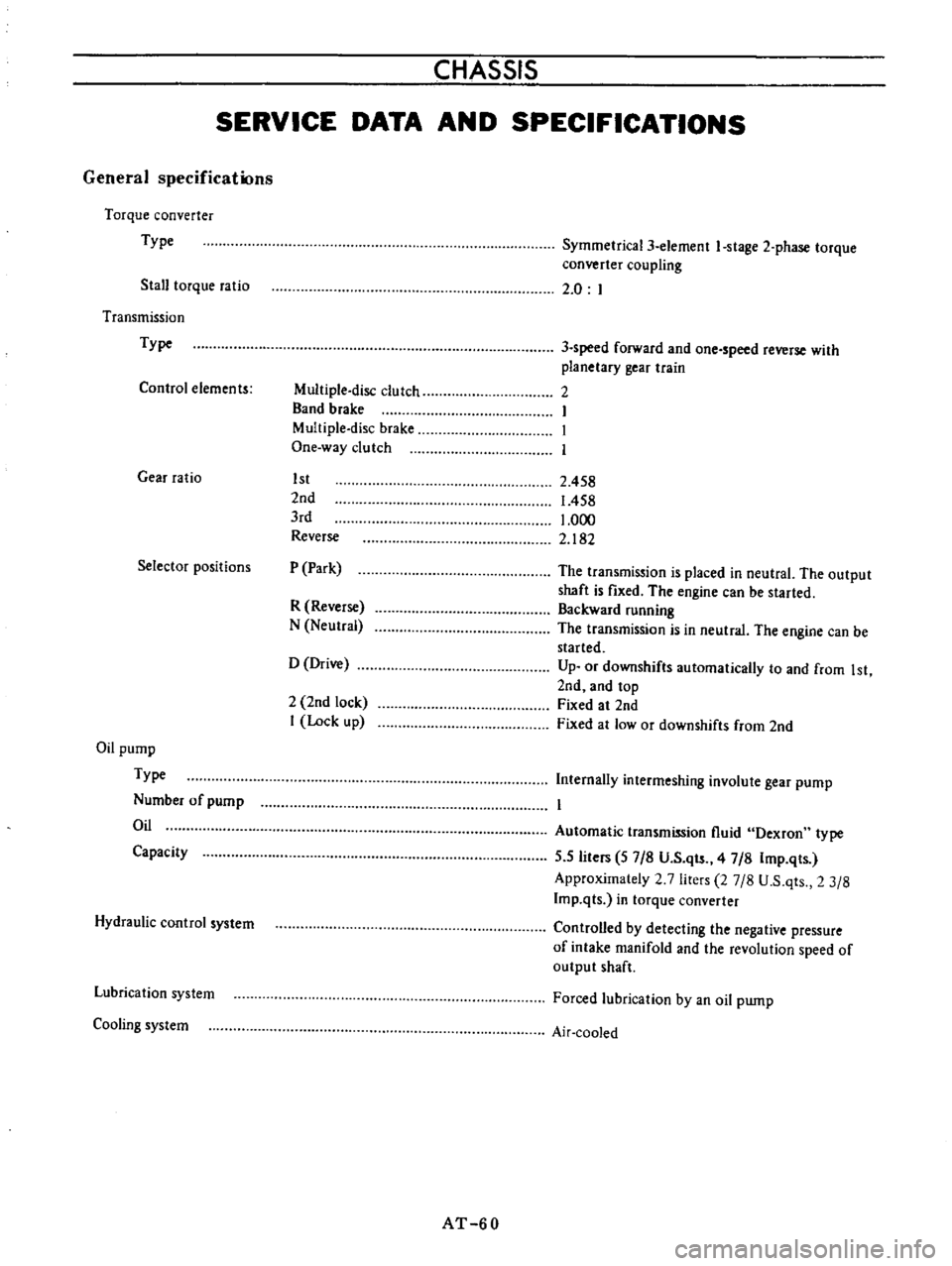
CHASSIS
SERVICE
DATA
AND
SPECIFICATIONS
General
specifications
Torque
converter
Type
Stall
torque
ratio
Transmission
Type
Control
elements
Gear
ratio
Selector
positions
Oil
pump
Type
Number
of
pump
Oil
Capacity
Hydraulic
control
system
Lubrication
system
Cooling
system
Multiple
disc
clutch
Band
brake
Multiple
disc
brake
One
way
clutch
1st
lnd
3rd
Reverse
P
Park
R
Reverse
N
Neutral
D
Drive
1
lnd
lock
I
Lock
up
AT
60
Symmetrical3
element
I
stage
l
phase
torque
converter
coupling
2
0
I
3
speed
forward
and
one
speed
reverse
with
planetary
gear
train
1
I
I
I
2
458
1
458
1
000
2
182
The
transmission
is
placed
in
neutral
The
output
shaft
is
fixed
The
engine
can
be
started
Backward
running
The
transmission
is
in
neutral
The
engine
can
be
started
Up
or
downshifts
automatically
to
and
from
1st
lnd
and
top
Fixed
at
2nd
Fixed
at
low
or
downshifts
from
2nd
Internally
intermeslting
involute
gear
pump
Automatic
transmission
fluid
Dexron
type
5
5
liters
57
8
U
S
qts
47
8
Imp
qts
Approximately
1
7
liters
27
8
U
S
qts
2
3
8
Imp
qts
in
torque
converter
Controlled
by
detecting
the
negative
pressure
of
intake
manifold
and
the
revolution
speed
of
output
shaft
Forced
lubrication
by
an
oil
pwnp
Air
cooled
Page 65 of 513
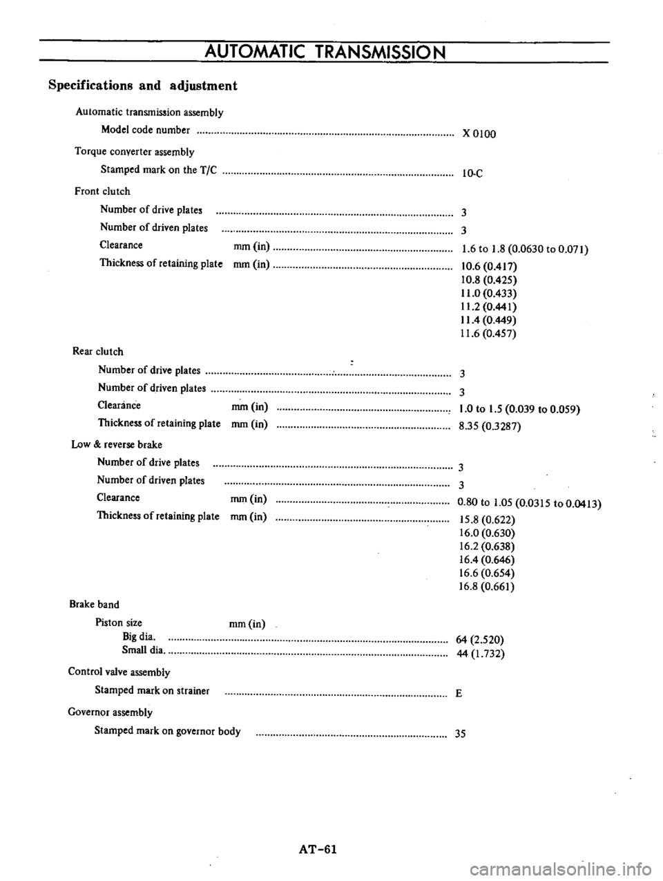
AUTOMATIC
TRANSMISSION
Specifications
and
adjustment
Automatic
transmission
assembly
Model
code
number
Torque
converter
assembly
Stamped
mark
on
the
TIC
Front
clu
tch
Number
of
drive
plate
Number
of
driven
plates
Clearance
Thickness
of
retaining
plate
Rear
clutch
Number
of
drive
plates
Number
of
driven
plate
Clearance
Thickness
of
retaining
plate
Low
reverse
brake
Number
of
drive
plates
Number
of
driven
plates
Clearance
Thickness
of
retaining
plate
Brake
band
Piston
size
Big
dia
Small
dia
Control
valve
assembly
Stamped
mark
on
trainer
Governor
assembly
Stamped
mark
on
governor
body
mm
in
mm
in
mm
in
mm
in
mm
in
mm
in
mm
in
AT
61
x
0100
IO
C
3
3
1
6
to
1
8
0
0630
to
0
071
10
6
0
417
10
8
0
425
11
0
0
433
11
2
0
441
II
4
0
449
11
6
0
457
3
3
1
0
to
1
5
0
039
to
0
059
8
35
0
3287
3
3
0
80
to
1
05
0
0315
to
0
0413
15
8
0
622
16
0
0
630
16
2
0
638
16
4
0
646
16
6
0
654
16
8
0
661
64
2
520
44
I
732
E
35
Page 66 of 513
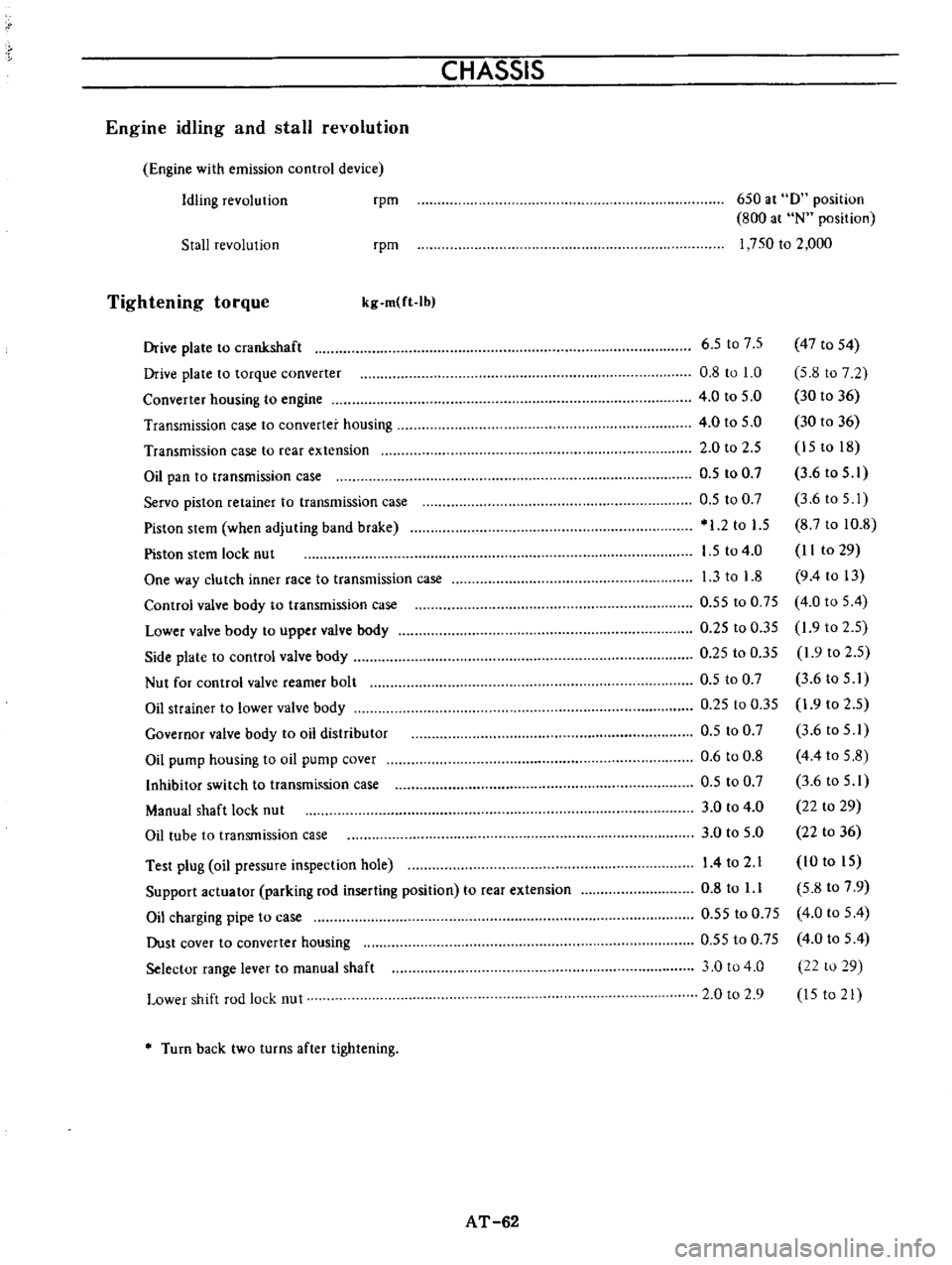
CHASSIS
Engine
idling
and
stall
revolution
Engine
with
emission
control
device
Idling
revolution
rpm
650
at
0
position
800
at
N
position
1
750
to
2
000
Stall
revolution
rpm
Tightening
torque
kg
m
ft
Ib
Test
plug
oil
pressure
inspection
hole
Support
actuator
parking
rod
inserting
position
to
rear
extension
Oil
charging
pipe
to
case
Dust
cover
to
converter
housing
Selector
range
lever
to
manual
shaft
Lower
shift
rod
lock
nut
6
5
t07
5
47
to
54
0
8
to
1
0
5
8
to
7
2
4
0
to
5
0
30
to
36
4
0
to
5
0
30
to
36
2
0
to
2
5
15
to
18
0
5
to
0
7
3
6
to
5
1
0
5
to
0
7
3
6toS
I
1
2
to
1
5
8
7
to
10
8
1
5
to
4
0
II
to
29
1
3
to
1
8
9
4
to
13
0
55
to
0
75
4
0
to
5
4
0
25
to
0
35
1
9
to
2
5
0
25
to
0
35
1
9
to
2
5
0
5
to
0
7
3
6
to
5
I
0
25
to
0
35
1
9
to
2
5
0
5
to
0
7
3
6
to
5
1
0
6
to
0
8
4
4
to
5
8
0
5
to
0
7
3
6
to
5
1
3
0
to
4
0
22
to
29
3
0
to
5
0
22
to
36
14
to
2
1
10
to
15
0
8
to
l
l
5
8
to
7
9
0
55
to
0
75
4
0
to
5
4
0
55
to
0
75
4
0
to
5
4
3
0
to
4
0
22
to
29
2
0
to
2
9
15
to
21
Drive
plate
to
crankshaft
Drive
plate
to
torque
converter
Converter
housing
to
engine
Transmission
case
to
converter
housing
Transmission
case
to
rear
extension
Oil
pan
to
transmission
case
Servo
piston
retainer
to
transmission
case
Piston
stem
when
adjuting
band
brake
Piston
stem
lock
nut
One
way
clutch
inner
race
to
transmission
case
Control
valve
body
to
transmission
case
Lower
valve
body
to
upper
valve
body
Side
plate
to
control
valve
body
Nut
for
control
valve
reamer
bolt
Oil
strainer
to
lower
valve
body
Governor
valve
body
to
oil
distributor
Oil
pump
housing
to
oil
pump
cover
Inhibitor
switch
to
transmh
sion
case
Manual
shaft
lock
nut
Oil
tube
to
transmission
case
Turn
back
two
turns
after
tightening
AT
62
Page 67 of 513
r
r
QRr
S
IJ
lrll
r
W
bI15
I
Q
ll
rrll
l
0
fl
AU
1
i
L
Ill
J
cr
U
J
r
Jj
I
DATSUN
1200
MODEL
B
11
0
SERIES
L
NISSAN
I
NISSAN
MOTOR
CO
LTD
TOKYO
JAPAN
I
I
i
I
I
I
SECTION
PD
PROPELLER
SHAFT
DIFFERENTIAL
CARRIER
PROPELLER
SHAFT
AND
UNIVERSAL
JOINT
DIFFERENTIAL
CARRIER
PD
1
PD
4
Page 68 of 513
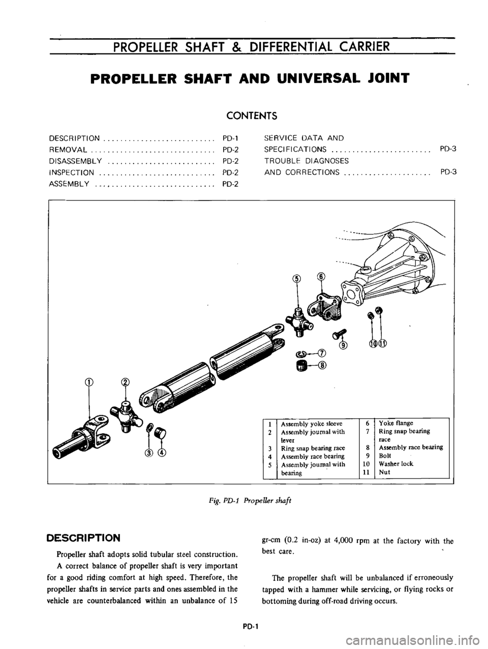
PROPELLER
SHAFT
DIFFERENTIAL
CARRIER
PROPELLER
SHAFT
AND
UNIVERSAL
JOINT
CONTENTS
DESC
R
I
PTI
ON
REMOVAL
DISASSEMBL
Y
INSPECTION
ASSEMBL
Y
PD
PD
2
PD
2
PD
2
PD
2
SERVICE
DATA
AND
SPECIFICATIONS
TROUBLE
DIAGNOSES
AND
CORRECTIONS
PD
3
PD
3
j
j
lI
ID
1
Assembly
yoke
sleeve
2
As
mbly
journal
with
lever
3
Ring
snap
bearing
race
4
Assembly
race
bearing
5
Assembly
journal
with
bearing
6
Yoke
flange
7
Ring
snap
bearing
race
8
Assembly
race
bearing
9
Bolt
10
Washer
lock
11
Nut
Fig
PD
l
Propeller
shaft
DESCRIPTION
Propeller
shaft
adopts
solid
tubular
steel
construction
A
correct
balance
of
propeller
shaft
is
very
important
for
a
good
riding
comfort
at
high
speed
Therefore
the
propeller
shafts
in
service
parts
and
ones
assembled
in
the
vehicle
are
counterbalanced
within
an
unbalance
of
IS
gr
cm
0
2
in
oz
at
4
000
rpm
at
the
factory
with
the
best
care
The
propeller
shaft
will
be
unbalanced
if
erroneously
tapped
with
a
hammer
while
servicing
or
flying
rocks
or
bottoming
during
off
road
driving
occurs
PD
1
Page 69 of 513
CHASSIS
Mureover
excessive
sleeve
yoke
spline
ta
transmission
main
spline
lash
and
wear
of
both
front
and
rear
universal
joints
will
cause
vibrations
affecting
riding
comfort
REMOVAL
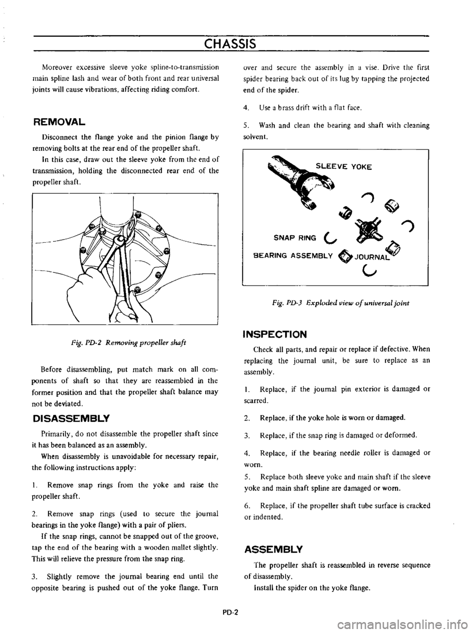
Disconnect
the
flange
yoke
and
the
pinion
flange
by
removing
bolts
at
the
rear
end
of
the
propeller
shaft
In
this
case
draw
out
the
sleeve
yoke
from
the
end
of
transmission
holding
the
disconnected
rear
end
of
the
propeller
shaft
Fig
PD
2
Removing
pmpeller
shaft
Before
disassembling
put
match
mark
on
all
com
ponents
of
shaft
so
that
they
are
reassembled
in
the
former
position
and
that
the
propeller
shaft
balance
may
not
be
deviated
DISASSEMBLY
Primarily
do
not
disassemble
the
propeller
shaft
since
it
has
been
balanced
as
an
assembly
When
disassembly
is
unavoidable
for
necessary
repair
the
following
instructions
apply
1
Remove
snap
rings
from
the
yoke
and
raise
the
propeller
shaft
2
Remove
snap
rings
used
to
secure
the
journal
bearings
in
the
yoke
flange
with
a
pair
of
pliers
If
the
snap
rings
cannot
be
snapped
out
of
the
groove
tap
the
end
of
the
bearing
with
a
wooden
mallet
slightly
This
will
relieve
the
pressure
from
the
snap
ring
3
Slightly
remove
the
journal
bearing
end
until
the
opposite
bearing
is
pushed
out
of
the
yoke
flange
Turn
over
and
secure
the
assembly
in
a
vise
Drive
the
first
spider
bearing
back
out
of
its
lug
by
tapping
the
projected
end
of
the
spider
4
Use
a
brass
drift
with
a
flat
face
5
Wash
and
clean
the
bearing
and
shaft
with
cleaning
solvent
1
W
SNAP
RING
V
I
1Iiff
BEARING
ASSEMBLY
JOURNA
V
Fig
PD
3
Exploded
view
of
universal
joint
INSPECTION
Check
all
parts
and
repair
or
replace
if
defective
When
replacing
the
journal
unit
be
sure
to
replace
as
an
assembly
Replace
if
the
journal
pin
exterior
is
damaged
or
scarred
2
Replace
if
the
yoke
hole
is
worn
or
damaged
3
Replace
if
the
snap
ring
is
damaged
or
deformed
4
Replace
if
the
bearing
needle
roller
is
damaged
or
worn
5
Replace
both
sleeve
yoke
and
main
shaft
if
the
sleeve
yoke
and
main
shaft
spline
are
damaged
or
worn
6
Replace
if
the
propeller
shaft
tube
surface
is
cracked
or
Indented
ASSEMBLY
The
propeller
shaft
is
reassembled
in
reverse
sequence
of
disassembly
Install
the
spider
on
the
yoke
flange
PD
2
Page 70 of 513
PROPELLER
SHAFT
DIFFERENTIAL
CARRIER
Insert
the
journal
into
the
yoke
flange
Tap
the
journal
bearing
into
the
yoke
flange
using
a
brass
drift
smaller
than
the
hole
in
the
yoke
Tap
the
other
bearing
into
the
opposite
end
of
the
yoke
flange
until
the
bearing
is
in
line
with
the
snap
ring
grooves
With
a
pair
of
pliers
install
the
snap
rings
on
both
ends
of
the
yoke
flange
Insert
the
flange
assembly
in
the
sleeve
yoke
Place
the
other
yoke
bearing
into
the
opposite
end
of
the
yoke
and
tap
this
bearing
into
the
yoke
until
the
bearing
is
in
line
with
the
snap
ring
grooves
Install
the
snap
rings
on
both
ends
of
the
yoke
When
all
parts
are
assembled
check
the
spider
and
surroundings
for
tightness
When
the
clearance
is
excessive
adjust
with
over
size
snap
rings
as
follows
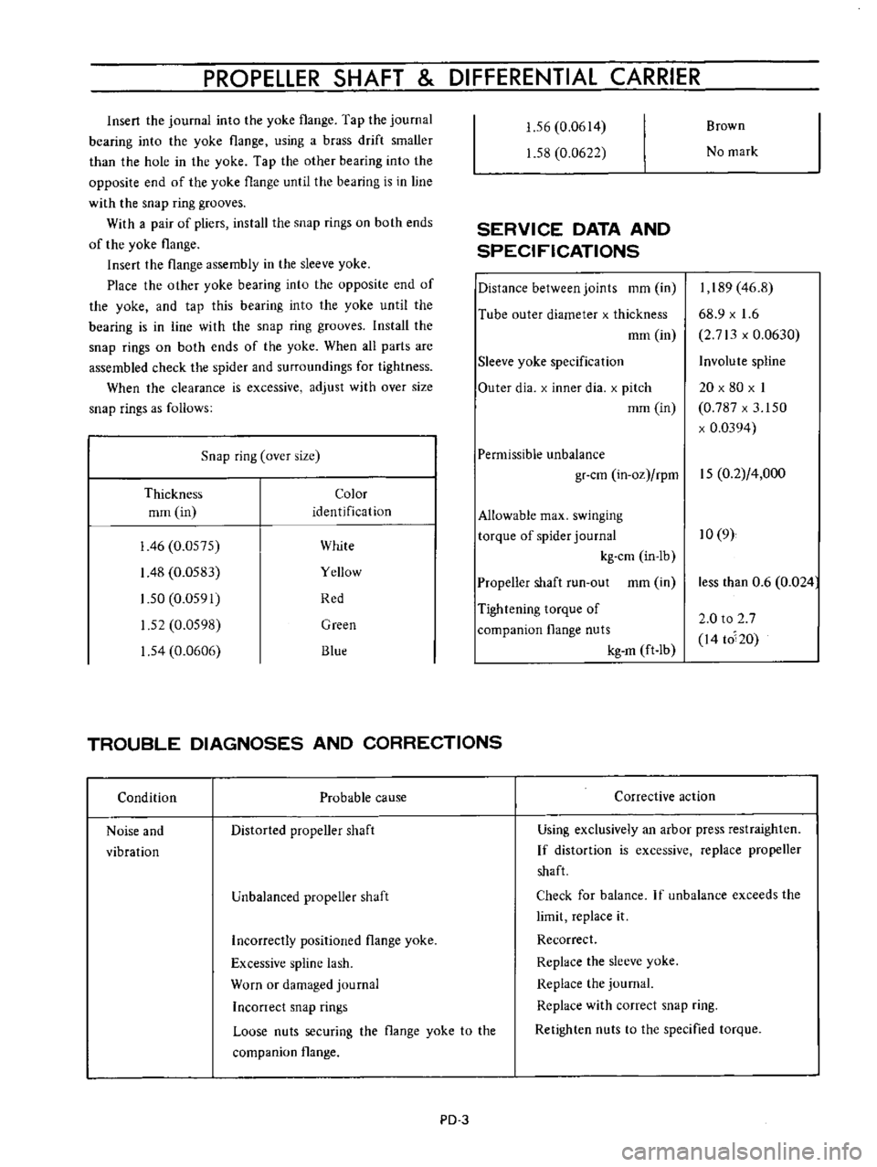
Snap
ring
over
size
Thickness
Color
mrn
in
identification
I
46
0
0575
White
I
48
0
0583
Yellow
1
50
0
0591
Red
1
52
0
0598
Green
1
54
0
0606
Blue
1
56
0
0614
1
58
0
0622
SERVICE
DATA
AND
SPECIFICATIONS
Distance
between
joints
mm
in
Tube
outer
diameter
x
thickness
mm
in
Sleeve
yoke
specification
Outer
dia
x
inner
dia
x
pitch
mm
in
Brown
No
mark
I
189
46
8
68
9
x
1
6
2
713
x
0
0630
Involute
spline
20
x
80
x
I
0
787
x
3
150
x
0
0394
Permissible
unbalance
gr
cm
in
oz
rpm
15
0
2
4
000
Allowable
max
swinging
torque
of
spider
journal
10
9
kg
cm
in
lb
Propeller
shaft
run
out
mm
in
Tightening
torque
of
companion
flange
nuts
kg
m
ft
Ib
TROUBLE
DIAGNOSES
AND
CORRECTIONS
Condition
Probable
cause
Noise
and
vibration
Distorted
propeller
shaft
Unbalanced
propeller
shaft
Corrective
action
less
than
0
6
0
024
2
0
to
2
7
I4
to
20
Using
exclusively
an
arbor
press
restraighten
If
distortion
is
excessive
replace
propeller
shaft
Check
for
balance
If
unbalance
exceeds
the
limit
replace
it
Recorrect
Replace
the
sleeve
yoke
Replace
the
journal
Replace
with
correct
snap
ring
Retighten
nuts
to
the
specified
torque
Incorrectly
positioned
flange
yoke
Excessive
spline
lash
Worn
or
damaged
journal
Inconect
snap
rings
Loose
nuts
securing
the
flange
yoke
to
the
companion
flange
PD
3