checking oil DATSUN PICK-UP 1977 User Guide
[x] Cancel search | Manufacturer: DATSUN, Model Year: 1977, Model line: PICK-UP, Model: DATSUN PICK-UP 1977Pages: 537, PDF Size: 35.48 MB
Page 62 of 537
Standard
Taper
and
out
of
round
of
journal
and
crank
pin
mm
in
less
than
0
01
0
0004
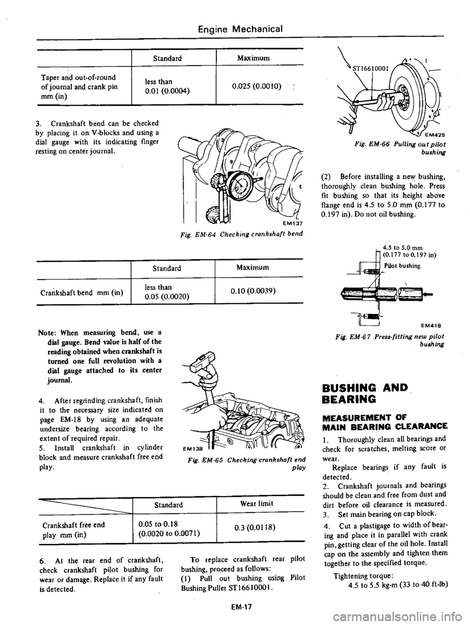
3
Crankshaft
bend
can
be
checked
by
placing
it
on
V
blocks
and
using
a
dial
gauge
with
its
indicating
finger
resting
on
center
journal
Standard
Crankshaft
bend
mm
in
less
than
0
05
0
0020
Note
When
measuring
bend
use
a
dial
gauge
Bend
value
is
half
of
the
reading
obtained
when
crankshaft
is
turned
one
full
revolution
with
a
dial
gauge
attached
to
its
center
journal
4
After
regrinding
crankshaft
finish
it
to
the
necessary
size
indicated
on
page
EM
18
by
using
an
adequate
undersize
bearing
according
to
the
extent
of
required
repair
5
Install
crankshaft
in
cylinder
block
and
measure
crankshaft
free
end
play
Engine
Mechanical
Maximum
0
Q25
0
0010
EM137
Fig
EM
64
Checking
crankshaft
bend
Maximum
0
10
0
0039
Fig
EM
65
Checking
crankshaft
end
play
Standard
Wear
limit
Crankshaft
free
end
play
mm
in
0
05
to
0
18
0
0020
to
0
0071
0
3
0
0118
6
At
the
rear
end
of
crankshaft
check
crankshaft
pilot
bushing
for
wear
or
damage
Replace
it
if
any
fault
is
detected
To
replace
crankshaft
rear
pilot
bushing
pro
ceed
as
follows
I
Pull
out
bushing
using
Pilot
Bushing
Puller
STl66
1000
I
EM
17
STl6610001
EM425
Fig
EM
66
Pulling
out
pilot
bushing
2
Before
installing
a
new
bushing
thoroughly
clean
bushing
hole
Press
fit
bushing
so
that
its
height
above
flange
end
is
4
5
to
5
0
mm
0
177
to
0
197
in
Do
not
oil
bushing
EM418
Fig
EM
67
Press
fitting
new
pilot
bush
ng
BUSHING
AND
BEARING
MEASUREMENT
OF
MAIN
BEARING
CLEARANCE
I
Thoroughly
clean
all
bearings
and
check
for
scratches
melting
score
or
wear
Replace
bearings
if
any
fault
is
detected
2
Crankshaft
journals
and
bearings
should
be
clean
and
free
from
dust
and
dirt
before
oil
clearance
is
measured
3
Set
main
bearing
on
cap
block
4
Cut
a
plastigage
to
width
of
bear
ing
and
place
it
in
parallel
with
crank
pin
getting
clear
of
the
oil
hole
Install
cap
on
the
assembly
and
tighten
them
together
to
the
specified
torque
Tightening
torque
4
5
to
5
5
kg
m
33
to
40
ft
lb
Page 65 of 537
I
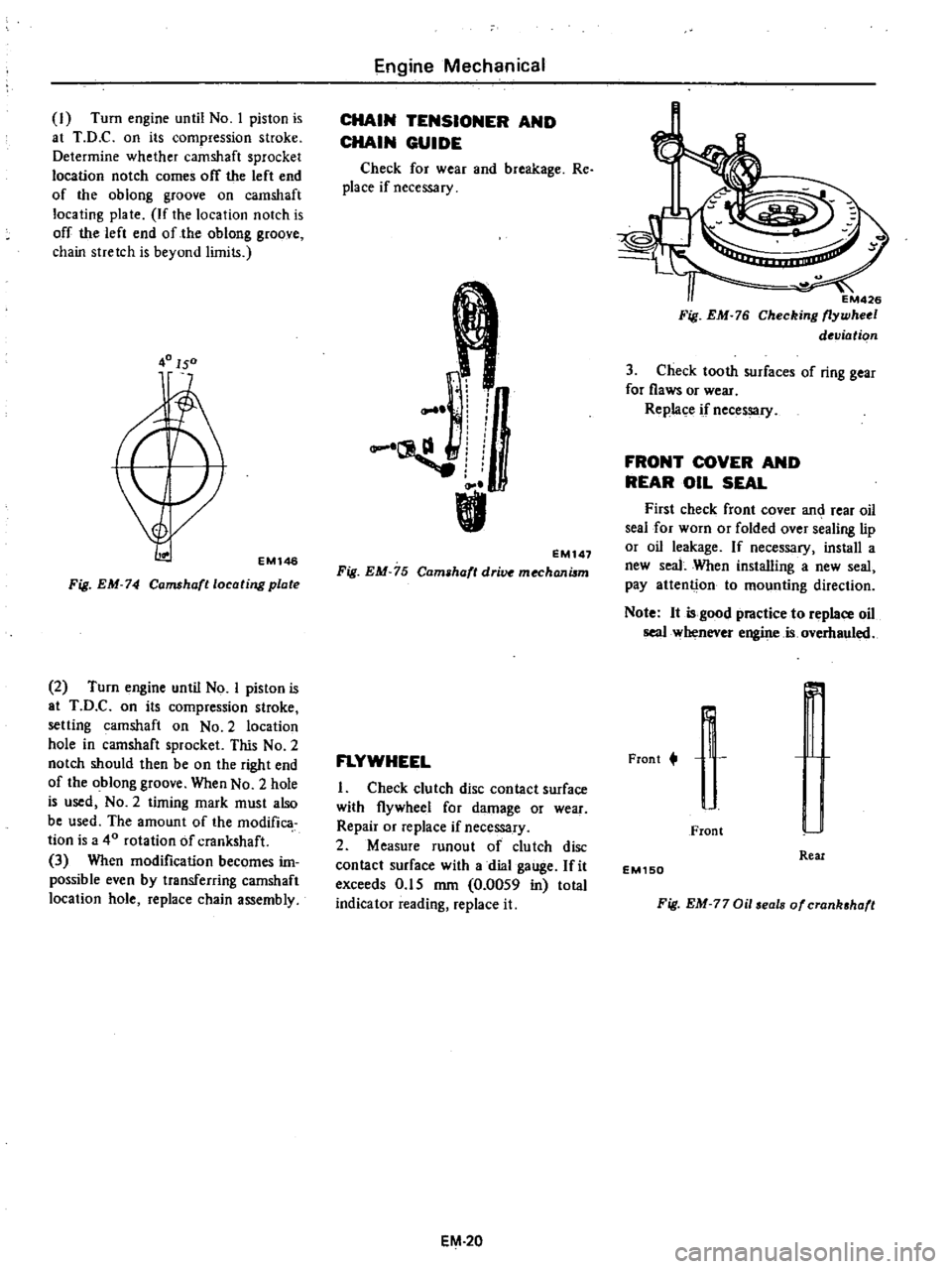
Turn
engine
until
No
I
piston
is
at
T
D
C
on
its
compression
stroke
Determine
whether
camshaft
sprocket
location
notch
comes
off
the
left
end
of
the
oblong
groove
on
camshaft
locating
plate
If
the
location
notch
is
off
the
left
end
of
the
oblong
groove
chain
stretch
is
beyond
limits
40150
EMl46
Fig
EM
74
Camshafllocating
plate
2
Turn
engine
until
No
I
piston
is
at
T
D
C
on
its
compression
stroke
setting
camshaft
on
No
2
location
hole
in
camshaft
sprocket
This
No
2
notch
should
then
be
on
the
right
end
of
the
oblong
groove
When
No
2
hole
is
used
NO
2
timing
mark
must
also
be
used
The
amount
of
the
modifica
tion
is
a
40
rotation
of
crankshaft
3
When
modification
becomes
im
possible
even
by
transferring
camshaft
location
hole
replace
chain
assembly
Engine
Mechanical
CHAIN
TENSIONER
AND
CHAIN
GUIDE
Check
for
wear
and
breakage
Re
place
if
necessary
r
I
L
EM147
Fig
EM
75
Cam
haft
dri
mechanilm
FLYWHEEL
I
Check
clutch
disc
contact
surface
with
flywheel
for
damage
or
wear
Repair
or
replace
if
necessary
2
Measure
runout
of
clutch
disc
contact
surface
with
a
dial
gauge
fit
exceeds
0
15
mm
0
0059
in
total
indicator
reading
replace
it
EM
20
EM426
Fig
EM
76
Checking
flywheel
deviation
3
Check
tooth
surfaces
of
ring
gear
for
flaws
or
wear
Replace
if
necessary
FRONT
COVER
AND
REAR
OIL
SEAL
First
check
front
cover
an
rear
oil
seal
for
worn
or
folded
over
sealing
lip
or
oil
leakage
If
necessary
install
a
new
seal
When
installing
a
new
seal
pay
attenti
on
to
mounting
direction
Note
It
is
good
practice
to
replace
oil
seal
whenever
engine
is
overhauled
Frant
t
r
r
J
I
Front
Real
EM150
Fig
EM
77
Oil
eals
of
crank
haft
Page 68 of 537
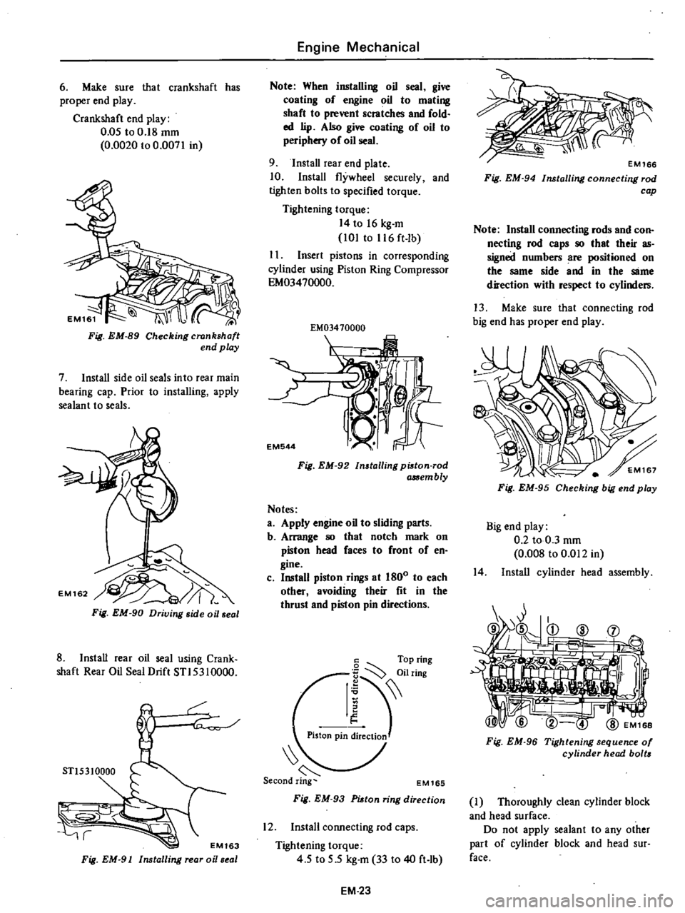
6
Make
sure
that
crankshaft
has
proper
end
play
Crankshaft
end
play
0
05
to
0
18
mm
0
0020
to
0
0071
in
Fig
EM
89
Checking
crankshaft
end
play
7
Install
side
oil
seals
into
rear
main
bearing
cap
Prior
to
installing
apply
sealant
to
seals
Fig
EM
90
Driving
side
oil
seal
8
Install
rear
oil
seal
using
Crank
shaft
Rear
Oil
Seal
Drift
STI5310000
r
STl5310000
r
EM163
Fig
EM
91
Installing
rear
oi
seal
Engine
Mechanical
Note
When
installing
oil
seal
give
coating
of
engine
oil
to
mating
shaft
to
prevent
scratches
and
fold
ed
lip
Also
give
coating
of
oil
to
periphery
of
oil
seal
9
Install
rear
end
plate
10
Install
flywheel
securely
and
tighten
bolts
to
specified
torque
Tightening
torque
14
to
16
kg
m
101
to
116
ft
lb
I
I
Insert
pistons
in
corresponding
cylinder
using
Piston
Ring
Compressor
EM03470000
EM03410000
I
EM544
Fig
EM
92
Installing
pi8ton
rod
a
Sembly
Notes
a
Apply
engine
oil
to
sliding
parts
b
Arrange
80
that
notch
mark
on
piston
head
faces
to
front
of
en
gine
c
Install
piston
rings
at
1800
to
each
other
avoiding
their
fit
in
the
thrust
and
piston
pin
directions
6
Top
ring
I
iilring
Piston
pin
ireClioJ
EM165
Fig
EM
93
PUtan
ring
direction
12
Install
connecting
rod
caps
Tightening
torque
4
5
to
5
5
kg
m
33
to
40
ft
lb
EM
23
Fig
EM
94
Installing
connecting
rod
cap
Note
Install
connecting
rods
and
con
necting
rod
caps
80
that
their
as
signed
numbers
are
positioned
on
the
same
side
and
in
the
SlIme
direction
with
respect
to
cylinders
13
Make
sure
that
connecting
rod
big
end
has
proper
end
play
Fig
EM
95
Checking
big
end
play
Big
end
play
0
2
to
0
3
mm
0
008
to
0
Ql2
in
14
Install
cylinder
head
assembly
Fig
EM
96
Tightening
sequence
01
cylinder
head
bolts
J
Thoroughly
clean
cylinder
block
and
head
surface
Do
not
apply
sealant
to
any
other
part
of
cylinder
block
and
head
sur
face
Page 86 of 537
ENGINE
LUBRICATION
SYSTEM
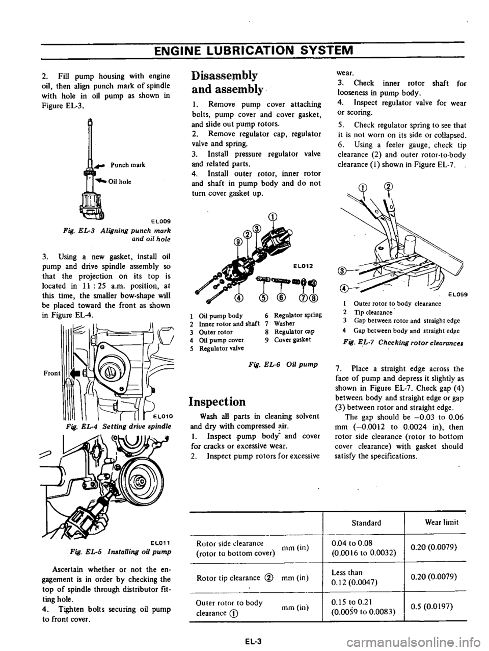
2
Fill
pump
housing
with
engine
oil
then
align
punch
mark
of
spindle
with
hole
in
oil
pump
as
shown
in
Figure
EL
3
Punch
mark
EL009
Fig
EL
3
Aligning
punch
mark
and
oil
hole
3
Using
a
new
gasket
install
oil
pump
and
drive
spindle
assembly
so
that
the
projection
on
its
top
is
located
in
II
25
a
m
position
at
this
time
the
smaller
bow
shape
will
be
placed
toward
the
front
as
shown
in
Figure
EL
4
JI
I
c
J
V
Front
J
@
9@
tr
i
d
L
It
I
I
EL010
Fig
EL
4
Setting
drive
pindle
o
EL011
Fig
EL
5
Imtalling
oil
pump
Ascertain
whether
or
not
the
en
gagement
is
in
order
by
checking
the
top
of
spindle
through
distributor
fit
ting
hole
4
Tighten
bolts
securing
oil
pump
to
front
cover
Disassembly
and
assembly
I
Remove
pump
cover
attaching
bolts
pump
cover
and
cover
gasket
and
slide
out
pump
rotors
2
Remove
regulator
cap
regulator
valve
and
spring
3
Install
pressure
regulator
valve
and
related
parts
4
Install
outer
rotor
inner
rotor
and
shaft
in
pump
body
and
do
not
turn
cover
gasket
up
CD
El012
r
@
@
CD@
1
Oil
pump
body
2
Inner
rotor
and
shaft
3
Outer
rotor
4
Oil
pump
cover
5
Regulator
valve
6
Regulator
spring
7
Washer
8
Regulator
cap
9
Cover
gasket
Fig
EL
6
Oil
pump
Inspection
Wash
all
parts
in
cleaning
solvent
and
dry
with
compressed
ir
I
Inspect
pump
body
and
cover
for
cracks
or
excessive
wear
2
Inspect
pump
rotors
for
excessive
Rotor
side
clearance
rotor
to
bottom
cover
Olm
in
Rotor
tip
clearance
@
mOl
in
Outer
rotor
to
body
clearance
D
mm
inl
EL
3
wear
3
Check
inner
rotor
shaft
for
looseness
in
pump
body
4
Inspect
regulator
valve
for
wear
or
scoring
5
Check
regulator
spring
to
see
that
it
is
not
worn
on
its
side
or
collapsed
6
Using
a
feeler
gauge
check
tip
clearance
2
and
outer
rotor
to
body
clearance
I
shown
in
Figure
EL
7
1
Outer
rotor
to
body
clearance
2
Tip
clearance
3
Gap
between
rotor
and
straight
edge
4
Gap
between
body
and
straight
edg
e
Fig
EL
7
Checking
rotor
clearance
7
Place
a
straight
edge
across
the
face
of
pump
and
depress
it
slightly
as
shown
in
Figure
EL
7
Check
gap
4
between
body
and
straight
edge
or
gap
3
between
rotor
and
straight
edge
The
gap
should
be
0
03
to
0
06
mm
0
0012
to
0
0024
in
then
rotor
side
clearance
rotor
to
bottom
cover
clearance
with
gasket
should
satisfy
the
specifications
Standard
Wear
limit
0
04
to
0
08
0
0016
to
0
0032
0
20
0
0079
Less
than
0
12
0
0047
0
20
0
0079
0
15
to
0
21
0
0059
to
0
0083
0
5
0
0197
Page 94 of 537
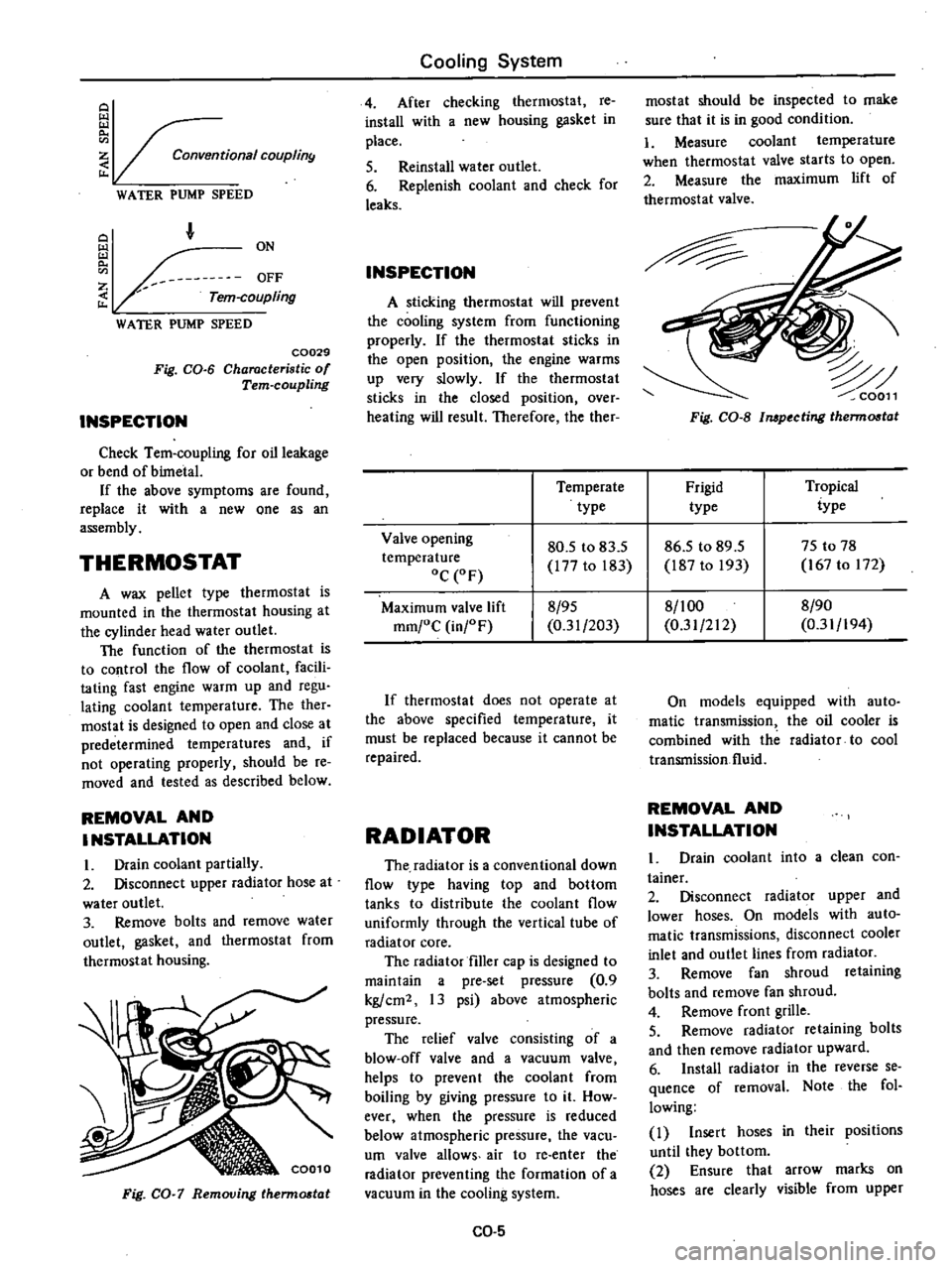
Conventional
COUplin9
WATER
PUMP
SPEED
F
Z
Tern
coupling
WATER
PUMP
SPEED
C0029
Fig
CO
6
Characteristic
of
Tern
coupling
INSPECTION
Check
Tem
coupling
for
oil
leakage
or
bend
of
bimetal
If
the
above
symptoms
are
found
replace
it
with
a
new
one
as
an
assembly
THERMOSTAT
A
wax
pellet
type
thermostat
is
mounted
in
the
thermostat
housing
at
the
cylinder
head
water
outlet
The
function
of
the
thermostat
is
to
control
the
flow
of
coolant
facili
tating
fast
engine
warm
up
and
regu
lating
coolant
temperature
The
ther
mostat
is
designed
to
open
and
close
at
predetermined
temperatures
and
if
not
operating
properly
should
be
re
moved
and
tested
as
described
below
REMOVAL
AND
INSTALLATION
I
Drain
coolant
partially
2
Disconnect
upper
radiator
hose
at
water
outlet
3
Remove
bolts
and
remove
water
outlet
gasket
and
thermostat
from
thermostat
housing
Fig
CO
7
Removing
therm06t
t
Cooling
System
4
After
checking
thermostat
re
install
with
a
new
housing
gasket
in
place
5
Reinstall
water
outlet
6
Replenish
coolant
and
check
for
leaks
INSPECTION
A
sticking
thermostat
will
prevent
the
cooling
system
from
functioning
properly
If
the
thermostat
sticks
in
the
open
position
the
engine
warms
up
very
slowly
If
the
thermostat
sticks
in
the
closed
position
over
heating
will
result
Therefore
the
ther
mostat
should
be
inspected
to
make
sure
that
it
is
in
good
condition
1
Measure
coolant
temperature
when
thermostat
valve
starts
to
open
2
Measure
the
maximum
lift
of
thermostat
valve
Fig
CO
S
Impecting
therm06t
t
Temperate
Frigid
Tropical
type
type
iype
Valve
opening
80
5
to
83
5
86
5
to
89
5
75
to
78
temperature
177
to
183
187
to
193
167
to
172
oC
OF
Maximum
valve
lift
8
95
8
1
00
8
90
mm
oC
in
F
0
31
203
0
31
212
0
31
194
If
thermostat
does
not
operate
at
the
above
specified
temperature
it
must
be
replaced
because
it
cannot
be
repaired
RADIATOR
The
radiator
is
a
conventional
down
flow
type
having
top
and
bottom
tanks
to
distribute
the
coolant
flow
uniformly
through
the
vertical
tube
of
radiator
core
The
radiator
filler
cap
is
designed
to
maintain
a
pre
set
pressure
0
9
kg
cm2
13
psi
above
atmospheric
pressure
The
relief
valve
consisting
of
a
blow
off
valve
and
a
vacuum
valve
helps
to
prevent
the
coolant
from
boiling
by
giving
pressure
to
it
How
ever
when
the
pressure
is
reduced
below
atmospheric
pressure
the
vacu
um
valve
allows
air
to
re
enter
the
radiator
preventing
the
formation
of
a
vacuum
in
the
cooling
system
CO
5
On
models
equipped
with
auto
matic
transmission
the
oil
cooler
is
combined
with
the
radiator
to
cool
transmission
fluid
REMOVAL
AND
INSTALLATION
Drain
coolant
into
a
clean
con
tainer
2
Disconnect
radiator
upper
and
lower
hoses
On
models
with
auto
matic
transmissions
disconnect
cooler
inlet
and
outlet
lines
from
radiator
3
Remove
fan
shroud
retaining
bolts
and
remove
fan
shroud
4
Remove
front
grille
5
Remove
radiator
retaining
bolts
and
then
remove
radiator
upward
6
Install
radiator
in
the
reverse
se
quence
of
removal
Note
the
fol
lowing
I
Insert
hoses
in
their
positions
until
they
bottom
2
Ensure
that
arrow
marks
on
hoses
are
clearly
visible
from
upper
Page 135 of 537

There
are
three
types
of
control
system
These
are
J
Closed
type
CIllnkcase
emission
control
system
Emission
Control
System
of
GENERAL
DESCRIPTION
2
Exhaust
emission
control
system
3
Evaporative
ell
lhsion
control
sys
tem
Pericxiic
inspection
and
required
seCV1Clng
of
these
systems
should
be
carried
out
to
reduce
harmful
emis
sions
to
a
minimum
CRANKCASE
EMISSION
CONTROL
SYSTEM
c
01
Lkf
If
1
TIL
II
tll
1
j
GUuuu
DESCRIPTION
This
system
returns
blow
by
gas
to
both
the
intake
manifold
and
carbure
tor
air
cleaner
The
positive
crankcase
ventilation
p
C
V
valve
is
provided
to
conduct
crankcase
blow
by
gas
to
the
intake
manifold
During
partial
throttle
operation
of
the
engine
the
intake
manifold
sucks
the
blow
by
gas
through
the
P
C
V
valve
Normally
the
capacity
of
the
valve
is
sufficient
to
handle
any
blow
by
and
a
small
amount
of
ventilating
air
4
c
Fresh
air
Blow
by
gas
The
ventilating
air
is
then
drawn
from
the
dust
side
of
the
cadlUretor
air
cleaner
tluough
the
tube
con
necting
carburetor
air
cleaner
to
rock
er
cover
into
the
crankcase
Under
full
tluottle
condition
the
manifold
vacuwn
is
insufficient
to
draw
the
blow
by
flow
tluough
the
valve
and
its
flow
goes
through
the
tube
connection
in
the
reverse
diree
tion
On
vehicles
with
an
excessively
high
blow
by
some
of
the
flow
will
go
through
the
tube
connection
to
carbu
retor
air
cleaner
under
all
conditions
1
Sealtypc
oil
level
gauge
2
Bame
plate
3
Flame
arrester
4
Filler
5
P
C
Y
valve
6
Steel
net
7
Bame
plate
EC716
Fig
EC
l
Crankcase
miaion
control
ay
tem
EC
2
INSPECTION
P
c
V
VALVE
AND
FILTER
Checking
P
C
V
valve
in
accord
ance
with
the
following
method
With
engine
running
at
idle
remove
the
ventilator
hose
from
P
C
V
valve
if
the
valve
is
working
a
hissing
noise
will
be
heard
as
air
passes
through
the
valve
and
a
strong
vacuwn
should
be
felt
immediately
when
a
fmger
is
placed
over
valve
inlet
Replace
P
C
V
valve
and
filter
in
accordance
with
the
maintenance
schedule
VENTILATION
HOSE
1
Check
hoses
and
hose
connec
tions
for
leaks
2
Disconnect
all
hoses
and
clean
with
compressed
air
If
any
hose
cannot
be
free
of
obstructions
replace
Ensure
that
flame
arrester
is
surely
inserted
in
hose
between
air
cleaner
and
rocker
cover
Page 140 of 537
REMOVAL
AND
INSTAUATION
Emission
Control
System
EC533
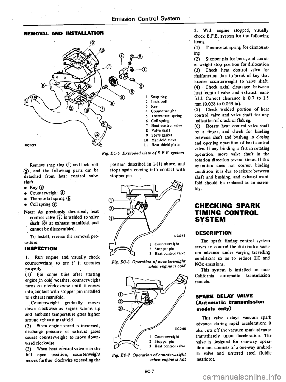
Remove
snap
ring
D
and
lock
bolt
@
and
the
following
parts
can
be
detached
from
heat
control
valve
shaft
Key
00
Counterweight
@
TherI
lostat
spring
CID
Coil
spring
@
Note
As
previously
descnoed
heat
control
valv
1
is
welded
to
valve
shaft
@
at
exhaust
manifold
and
cannot
be
disassembled
To
install
reverse
the
removal
pro
cedure
INSPECTION
I
Run
engine
and
visually
check
counterweight
to
see
if
it
operates
properly
1
For
some
time
after
starling
engine
in
cold
weather
counterweight
turns
counterclockwise
until
it
comes
into
contact
with
stopper
pin
installed
to
exhaust
manifold
Counterweight
gradually
moves
down
clockwise
as
engine
warms
up
and
ambient
temperature
goes
higher
around
exhaust
manifold
2
When
engine
speed
is
increased
discharge
pressure
of
exhaust
gases
causes
counterweight
to
move
down
ward
clockwise
3
When
heat
con
trol
valve
is
in
the
full
open
position
coun
terweight
moves
further
clockwise
exceeding
the
1
Snap
ring
2
Lock
bolt
3
Key
4
Counterweight
5
Thermostat
spring
6
Coil
spring
7
Heat
control
valve
8
Valve
shaft
9
Stove
gasket
10
Manifold
stove
11
Heat
shield
plate
Fig
EC
5
Exploded
view
of
E
F
E
stem
position
described
in
1
1
above
and
stops
again
coming
into
con
tact
with
stopper
pin
j
EC246
1
Counterweight
2
S
topper
pin
3
Heat
control
valve
Fig
EC
6
Operation
of
counterweight
when
engine
is
cold
EC246
1
Counterweight
2
Stopper
pin
3
Heat
control
valve
Fig
EC
7
Operation
of
counterw
ight
when
ngine
is
hot
EC
7
2
With
engine
stopped
visually
check
E
F
E
system
for
the
following
items
1
Thermostat
spring
for
dismount
ing
2
Stopper
pin
for
bend
and
count
er
weight
stop
position
for
dislocation
3
Check
heat
control
valve
for
malfunction
due
to
break
of
key
that
locates
counterweight
to
valve
shaft
4
Check
axial
clearance
between
heat
control
valve
and
exhaust
mani
fold
Correct
clearance
is
0
7
to
1
5
mm
0
028
to
0
059
in
5
Check
welded
portion
of
heat
control
valve
and
valve
shaft
for
any
indication
of
crack
or
flaking
6
Rotate
heat
control
valve
shaft
by
a
finger
and
check
for
binding
between
shaft
and
bushing
in
closing
and
opening
operation
of
heat
control
valve
If
any
binding
is
felt
in
rotating
operation
move
valve
shaft
in
the
rotation
direction
several
times
If
this
operation
does
not
correct
binding
condition
it
is
due
to
seizure
between
shaft
and
bushing
and
exhaust
mani
fold
should
be
replaced
as
an
assem
bly
CHECKING
SPARK
TIMING
CONTROL
SYSTEM
DESCRIPTION
The
spark
tirnin
control
system
serves
to
control
the
distributor
vacu
um
advance
under
varying
travelling
conditions
so
as
to
reduce
HC
and
NOx
emissions
This
system
is
installed
on
non
California
automatic
transmission
models
SPARK
DELAY
VALVE
Automatic
transmission
models
only
This
valve
delays
vacuum
spark
advance
during
rapid
acceleration
it
also
cuts
off
the
vacuwn
spark
advance
immediately
upon
deceleration
The
valve
is
designed
for
one
way
opera
tion
and
consists
of
a
one
way
umbrel
la
valve
and
sinlered
steel
fluidic
restrictor
Page 141 of 537

Emission
Control
System
C
bur
tor
I
EC284
When
installing
this
valve
ensure
that
it
properly
oriented
Tlus
valve
shuuld
be
replaced
periodically
Refer
to
Maintenance
Schedule
Note
Carburetor
side
Black
DisInDutor
side
Brown
horn
distributor
To
carburetor
TOdi
ribUI0
carburClor
EC
lCiJr
Fig
EC
9
Operation
01
park
delay
value
INSPECTION
Remove
spark
delay
valve
2
Blow
air
through
port
on
carbure
tor
side
then
through
the
other
port
on
distributor
side
Spark
delay
valve
Distributor
side
1
One
way
umbrella
valve
2
Sintered
metal
disc
Fig
EC
8
Spark
delay
valve
is
in
good
condition
if
when
finger
is
placed
over
port
on
distributor
side
air
flow
resistance
is
greater
than
that
on
the
other
side
See
Figur
ET
lO
3
If
a
considerable
air
flow
resist
ance
is
fell
at
port
on
distributor
side
in
step
2
above
and
if
the
condition
of
spark
delay
valve
is
questionable
dip
port
on
carburetor
side
into
a
cup
filled
with
water
Blow
air
through
the
other
port
Small
air
bubbles
should
appear
Carburetor
side
Distributor
side
EC346
Fig
EC
IO
Checking
park
delay
valve
EC
8
EC219
Fig
EC
11
Checking
spark
d
tay
valve
Note
Be
careful
to
avoid
entry
of
oil
or
dirt
into
valve
AIR
INJECTION
SYSTEM
DESCRIPTION
The
Air
Injection
System
A
LS
is
aeSigiieino
iiiject
coin
pressed
air
sec
ODllary
air
corning
from
the
air
pump
into
the
exhaust
manifold
to
reduce
hydrocarbons
and
carbon
monoxide
in
exhaust
lri
s
through
re
combustion
There
are
two
types
of
A
I
S
One
type
is
mounted
on
California
models
and
the
other
is
on
non
California
models
The
non
California
type
con
sists
of
an
air
pump
air
cleaner
an
air
pump
a
relief
valve
a
check
valve
an
anti
backfIre
valve
an
air
gallery
and
hoses
The
California
type
has
in
addition
to
the
components
of
the
non
California
type
an
air
control
valve
and
an
emergency
air
relief
valve
These
valves
prevent
ahnonnal
tem
perature
rise
of
the
catalytic
converter
Page 157 of 537
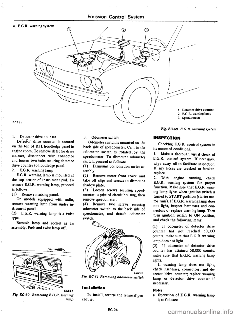
4
E
G
R
warning
system
EC251
Detector
drive
counter
Detecfor
drive
counter
is
secured
on
the
top
of
R
H
hoodledge
panel
in
engine
room
To
remove
detector
drive
counter
disconnect
w
COJUlector
and
loosen
two
bolts
securing
detector
drive
counter
to
hoodledge
panel
2
E
G
R
warning
lamp
E
G
R
warning
lamp
is
mounted
at
the
top
cen
ter
of
instrument
pad
To
remove
E
G
R
warning
lamp
proceed
as
follows
1
Remove
masking
panel
On
models
equipped
with
radio
remove
warning
lamp
from
under
in
strument
panel
2
E
G
R
warning
lamp
is
a
twist
type
Remove
lamp
and
socket
as
an
assembly
Push
and
twist
lamp
off
can
EC554
Fig
EC
60
Removing
E
G
R
warning
lamp
Emission
Control
System
3
Odometer
switch
Odometer
switch
is
mounted
on
the
back
side
of
speedometer
Cam
in
the
odometer
switch
is
rotated
by
the
speedometer
To
dismount
odometer
switch
proceed
as
follows
I
Dismount
combination
meter
as
sembly
2
Remove
meter
front
cover
and
take
off
clips
and
screws
to
dismount
shadow
plate
3
Loosen
screws
securing
speed
ometer
to
printed
circuit
housing
then
remove
speedometer
4
Remove
two
screws
securing
odomete
switch
to
the
back
side
of
speedometer
and
detach
odometer
switch
EC239
Fig
EC
61
Removing
odometer
switch
InstaUatlon
To
install
reverse
the
removal
pro
cedure
EC24
V
r
CID
1
Detector
drive
counter
2
E
G
R
warning
lamp
3
Speedometer
Fig
EC
59
E
G
R
warning
y
tem
INSPECTION
Checking
E
G
R
control
system
in
its
mounted
conditionS
I
Make
a
thorough
visual
check
of
E
G
R
control
system
If
necessary
wipe
away
oil
to
facilitate
inspection
If
any
hoses
are
cracked
or
broken
replace
2
With
engine
running
check
E
G
R
warning
system
for
proper
function
Make
sure
that
E
G
R
warn
ing
lamp
lights
when
ignition
switch
is
turned
to
START
position
starter
mo
tor
runs
If
E
G
R
wanung
lamp
does
not
light
inspect
harnesses
and
con
nectors
or
replace
warning
lamp
Then
turn
ignition
switch
to
ON
position
and
check
the
following
items
I
If
odometer
of
detector
drive
counter
has
not
reached
50
000
counts
make
sure
that
E
G
R
warning
lamp
does
not
light
2
If
odomete
of
detector
drive
counter
has
attained
50
000
counts
make
sure
that
E
G
R
warning
lamp
lights
If
warning
lamp
does
not
light
check
harnesses
connectors
and
de
tector
drive
counter
replace
warning
lamp
or
detector
drive
counter
if
necessary
Notes
Operation
oC
E
G
R
warning
lamp
is
as
Collows
Page 198 of 537
CHECKING
AND
ADJUSTMENT
CAP
AND
ROTOR
HEAD
Cap
and
rotor
head
should
be
in
spected
periodically
as
specified
in
the
Maintenance
Schedule
Remove
cap
and
clean
all
dust
and
carbon
deposits
from
cap
and
rotor
If
cap
is
cracked
or
is
leaking
replace
with
a
De
one
CONTACT
POINT
Contact
point
should
be
replaced
in
accordance
with
the
Maintenance
Schedule
Standard
point
gap
is
0
45
to
0
55
mm
O
OIS
to
0
022
in
In
case
size
is
off
the
standard
adjustment
is
made
by
loosening
point
screws
Gap
gauge
is
required
for
adjustment
When
point
surface
is
rough
take
off
any
irregularities
with
fine
sand
paper
of
No
500
or
600
or
with
oil
stone
When
wear
on
contact
points
is
noticeable
replace
points
together
with
contact
arm
To
replace
proceed
as
follows
EE322
Fig
EE
58
Adju
ting
point
gap
EE321
I
Primary
lead
termina
2
Ground
lead
wire
3
Set
screw
4
Adjuster
5
Screw
Fig
EE
59
Breaker
Engine
Electrical
System
First
turn
out
set
screws
1
to
1
5
turns
at
contact
arm
and
primary
lead
wire
connection
just
for
enough
to
pull
out
primary
lead
terminal
Referring
to
Figure
EE
59
unSCrew
two
contact
set
fixing
screws
and
remove
lead
wire
While
holding
contact
arm
by
fingers
pull
out
contact
set
toward
you
by
raising
it
slightly
Contact
point
and
afm
can
then
be
removed
together
Install
new
contact
point
and
arm
assembly
in
reverse
sequence
of
removal
Coat
cam
with
a
light
coating
of
grease
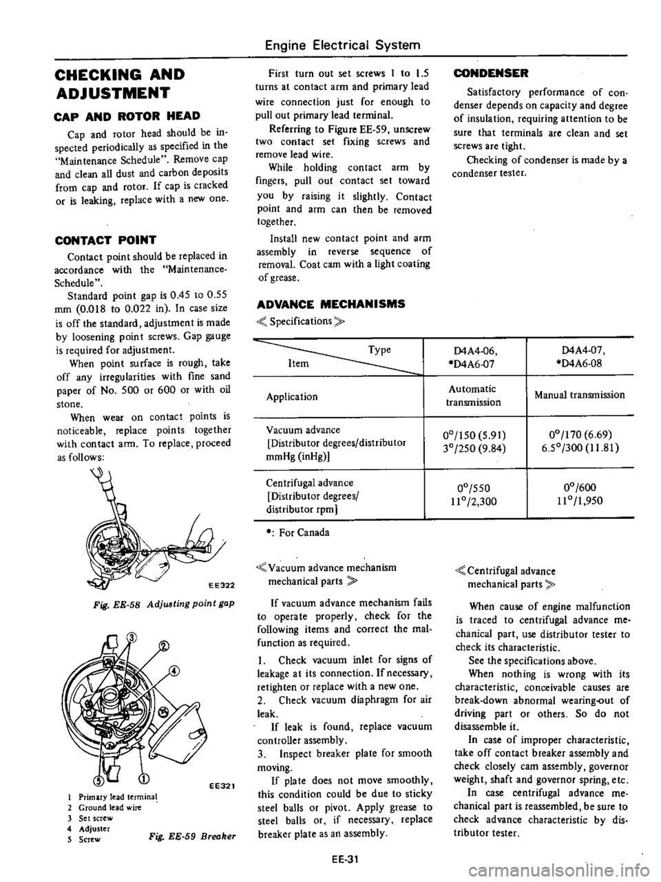
ADVANCE
MECHANISMS
Specifications
Application
Vacuum
advance
Distributor
degrees
distributor
mmHg
inHg
Centrifugal
advance
Distributor
degrees
distribu
tor
rpm
For
Canada
Vacuum
advance
mechanism
mechanical
parts
If
vacuum
advance
mechanism
fails
to
operate
properly
check
for
the
following
items
and
correct
the
mal
function
as
required
1
Check
vacuum
inlet
for
signs
of
leakage
at
its
connection
Ifnecessacy
retighten
or
replace
with
a
new
one
2
Check
vacuum
diaphragm
for
air
leak
If
leak
is
found
replace
vacuum
controller
assembly
3
Inspect
breaker
plate
for
smooth
moving
If
pia
te
does
not
move
smoothly
this
condition
could
be
due
to
sticky
steel
balls
or
pivot
Apply
grease
to
steel
balls
or
if
necessary
replace
breaker
plate
as
an
assembly
EE
31
CONDENSER
Satisfactory
performance
of
con
denser
depends
on
capacity
and
degree
of
insulation
requiring
attention
to
be
sure
that
terminals
are
clean
and
set
screws
are
tight
Checking
of
condenser
is
made
by
a
condenser
tester
D4A4
06
D4A6
07
D4A4
07
D4A6
0S
Automatic
transmission
Manual
transmission
00
150
5
91
30
250
9
S4
00
170
6
69
6
50
300
1I
S1
00
550
11
0
2
300
00
600
110
1
950
Centrifugal
advance
mechanical
parts
When
cause
of
engine
malfunction
is
traced
to
centrifugal
advance
me
chanical
part
use
distributor
tester
to
check
its
characteristic
See
the
specifications
above
When
nothing
is
wrong
with
its
characteristic
conceivable
causes
are
break
down
abnormal
wearing
out
of
driving
part
or
others
So
do
not
disassemble
it
In
case
of
improper
characteristic
take
off
contact
breaker
assembly
and
check
closely
cam
assembly
governor
weight
shaft
and
governor
spring
etc
In
case
centrifugal
advance
me
chanical
part
is
reassembled
be
sure
to
check
advance
characteristic
by
dis
tributor
tester