key battery DATSUN PICK-UP 1977 Service Manual
[x] Cancel search | Manufacturer: DATSUN, Model Year: 1977, Model line: PICK-UP, Model: DATSUN PICK-UP 1977Pages: 537, PDF Size: 35.48 MB
Page 161 of 537

I
Emission
Control
System
Ignition
switch
Ignition
key
Off
T
I
I
I
Battery
I
J
77
77
Relay
J
Floor
temperature
sensing
swi
tch
Floor
temperature
warning
lamp
77
77
EC332
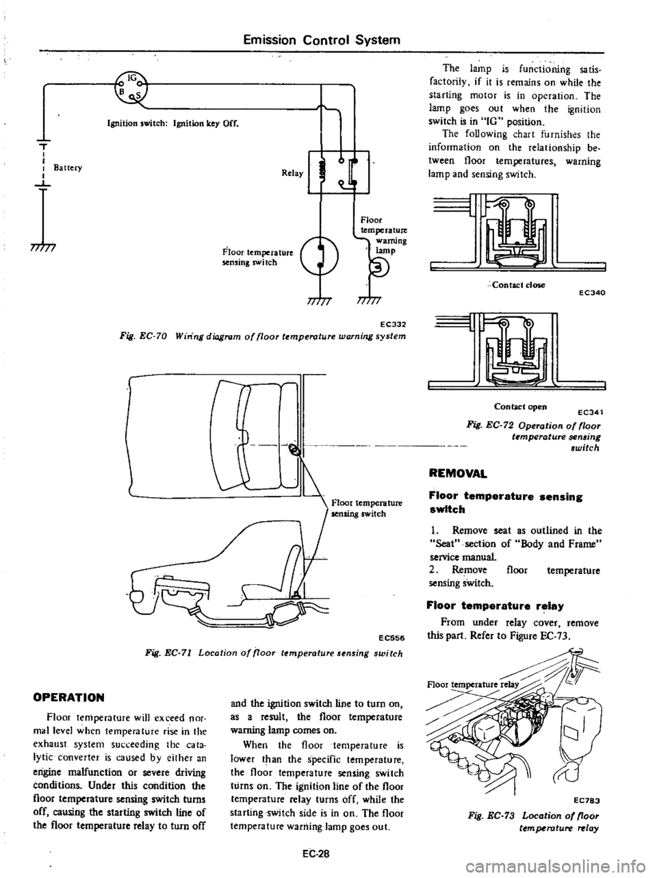
Fig
EC
70
Win
ng
diagram
of
floor
temperature
warning
system
r
l
J
@
1
Floor
temperature
Ij
cr
EC556
Fig
EC
71
Location
of
iJoor
temperature
sensing
switch
OPERATION
Floor
temperature
will
exceed
nor
mal
level
when
temperature
rise
in
the
exhaust
system
succeeding
the
cata
lytic
converter
is
caused
byeilher
an
engine
malfunction
or
severe
driving
conditions
Under
this
condition
the
floor
temperature
sensing
switch
turns
off
causing
the
starting
switch
line
of
the
floor
temperature
relay
to
turn
off
and
the
ignition
switch
line
to
turn
on
as
a
result
the
floor
temperature
warning
lamp
comes
on
When
the
floor
temperature
is
lower
t
an
the
specific
temperature
the
floor
temperature
sensing
switch
turns
on
The
ignition
line
of
the
floor
temperature
relay
turns
off
while
the
starting
switch
side
is
in
on
The
floor
temperature
warning
lamp
goes
out
EC
2B
The
lamp
is
functioning
sa
tis
factorily
if
it
is
remains
on
while
the
starting
motor
is
in
operation
The
lamp
goes
out
when
the
ignition
switch
is
in
IG
position
The
foUowing
chart
furnishes
the
information
on
the
relationship
be
tween
floor
temperatures
warning
lamp
and
sensing
switch
L
Contact
close
ECJ40
I
Contaclopen
ECJ41
Fig
EC
72
Operation
of
floor
t
mperature
sen6ing
6witch
REMOVAL
Floor
temperature
sensing
switch
1
Remove
seat
Seat
section
of
service
manual
2
Remove
sensing
sWitch
as
outlined
in
the
Body
and
Frame
floor
temperature
Floor
temperature
relay
From
under
relay
cover
remove
this
part
Refer
to
Figure
EC
73
Floortemperature
EC783
Fig
EC
73
Location
of
floor
ttmperature
relay
Page 173 of 537

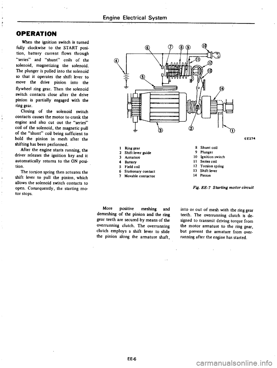
OPERATION
When
the
ignition
switch
turned
fully
clockwise
to
the
START
posi
tion
battery
current
flows
through
series
and
shunt
coils
of
the
solenoid
magnetizing
the
solenoid
The
plunger
is
pulled
into
the
solenoid
so
that
it
operates
the
shift
lever
to
move
the
drive
pinion
into
the
flywheel
ring
gear
Then
the
solenoid
switch
contacts
close
after
the
drive
pinion
is
partially
engaged
with
the
ring
gear
Closing
of
the
solenoid
switch
contacts
c
uses
the
motor
to
crank
the
engine
and
also
cut
out
the
series
coil
of
the
solenoid
the
magnetic
pull
of
the
shunt
coil
being
sufficient
to
hold
the
pinion
in
mesh
after
the
shifting
has
been
performed
After
the
engine
starts
running
the
driver
releases
the
ignition
key
and
it
automatically
returns
to
the
ON
posi
tion
The
torsion
spring
then
actuates
the
shift
lever
to
pull
the
pinion
which
allows
the
solenoid
swi
tch
contacts
to
open
Consequently
the
starting
mo
tor
stops
Engine
Electrical
System
I
I
Ring
gear
2
Shift
lever
guide
3
Armature
4
Battery
5
Field
coil
6
Stationary
contact
7
Monble
contactor
More
positive
meshing
and
demeshing
of
the
pinion
and
the
ring
gear
teeth
are
secured
by
means
of
the
overrunning
clutch
The
overruIUling
clutch
employs
a
shift
lever
to
slide
the
pinion
along
the
armature
shaft
EE
6
F
l
cp
o
r
1
I
I
W
m
EE274
8
Shunt
coil
9
Plunger
10
Ignition
switch
11
Series
coil
12
Torsion
spring
13
Shift
lever
14
Pinion
Fig
EE
7
Starting
motor
circuit
into
or
out
of
mesh
with
the
ring
gear
teeth
The
overrunning
clutch
is
de
signed
to
transmit
driving
torque
from
the
motor
armature
to
the
ring
gear
but
prevent
the
armature
from
over
running
after
the
engine
has
started
Page 467 of 537

Body
Electrical
System
Horn
switch
The
horn
switch
is
integral
with
the
turn
signal
and
dimmer
switch
as
sembly
Remove
switch
assembly
as
outlined
in
Turn
Signal
and
Dimmer
Switch
IGNITION
SWITCH
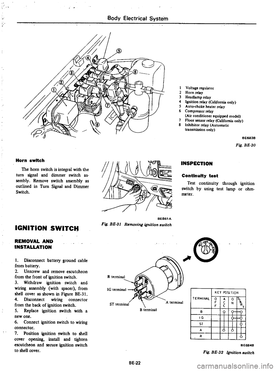
BE861A
Fig
BE
3
I
Removing
ignition
switch
REMOVAL
AND
INSTALLATION
I
Disconnect
battery
ground
cable
from
battery
2
Unscrew
and
remove
escutcheon
from
the
front
of
ignition
switch
3
Withdraw
ignition
switch
and
wiring
assembly
with
spacer
from
shell
cover
as
shown
in
Figure
BE
3
4
Disconnect
wiring
connector
from
the
back
of
ignition
switch
5
Replace
ignition
switch
with
a
new
one
6
Connect
ignition
switch
to
wiring
connector
7
Position
ignition
switch
to
shell
cover
opening
install
and
tighten
escutcheon
and
secure
ignition
switch
to
shell
cover
R
terminal
1G
terminal
ST
terminal
B
terminal
8E
22
1
Voltage
regulator
2
Horn
relay
3
Headlamp
relay
4
Ignition
relay
California
only
5
Auto
choke
heater
relay
6
Compressor
relay
Au
conditioner
equipped
model
7
Floor
sensor
relay
California
only
8
Inhibitor
relay
Automatic
tran5mission
only
INSPECTION
BE683B
Fig
BE
30
ContInuity
test
Test
continuity
through
ignition
switch
by
using
test
lamp
or
ohm
meter
C
A
terminal
TERMINAL
0
F
F
B
IG
ST
A
R
KEY
FOSITlON
t
1
o
j
u
u
I
I
A
C
C
Fig
BE
32
Ignition
witch
BE6848
Page 476 of 537

SEAT
BELT
WARNING
SYSTEM
DESCRIPTION
Except
Canada
When
the
ignition
switch
is
turned
to
the
ON
position
the
warning
lamp
comes
on
and
remains
on
for
4
to
8
seconds
The
warning
buzzer
sounds
for
4
to
8
seconds
intermittent
ly
if
the
driver
s
seat
belt
is
not
fastened
properly
The
seat
belt
warning
system
con
sists
of
a
driver
s
belt
switch
a
warning
buzzer
a
warning
lamp
a
timer
unit
and
an
ignition
switch
For
Canada
When
the
ignition
switch
is
turned
Body
Electrical
System
to
the
ON
position
the
warning
lamp
comes
on
and
the
warning
buz
zer
sounds
if
the
driver
s
seat
belt
is
not
fastened
properly
The
seat
belt
warning
system
con
sists
of
a
driver
s
belt
switch
a
warning
buzzer
a
warning
lamp
and
an
igni
tion
switch
REMOVAL
AND
INSTALLATION
Ignition
switch
Refer
to
page
BE
22
for
Removal
and
Installation
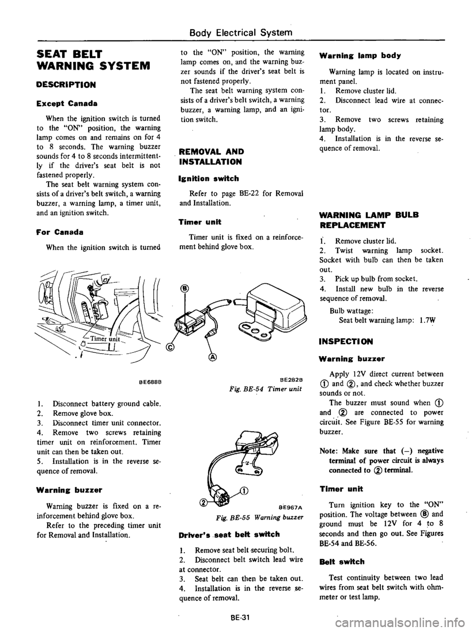
Timer
unit
Timer
unit
is
fIXed
on
a
reinforce
ment
behind
glove
box
BE688B
I
Disconnect
battery
ground
cable
2
Remove
glove
box
3
Disconnect
timer
unit
connector
4
Remove
two
screws
retaining
timer
unit
on
reinforcement
Timer
unit
can
then
be
taken
out
S
Installation
is
in
the
reverse
se
quence
of
removal
Warning
buzzer
Warning
buzzer
is
fIxed
on
a
re
inforcement
behind
glove
box
Refer
to
the
preceding
timer
unit
for
Removal
and
Installation
BE282B
Fig
BE
54
Timer
unit
BE967A
Fig
BE
55
Warning
buzzer
Driver
s
seat
belt
switch
I
Remove
seat
belt
ecuring
bolt
2
Disconnect
belt
switch
lead
wire
at
connector
3
Seat
belt
can
then
be
taken
out
4
Installation
is
in
the
reverse
se
quence
ofremoval
BE
31
Warning
lamp
body
Warning
lamp
is
located
on
instru
ment
panel
I
Remove
cluster
lid
2
Disconnect
lead
wire
at
connee
tor
3
Remove
two
screws
retaining
lamp
body
4
Installation
is
in
the
reverse
se
quence
of
removal
WARNING
LAMP
BULB
REPLACEMENT
I
Remove
cluster
lid
2
Twist
warning
lamp
socket
Socket
with
bulb
can
then
be
taken
out
3
Pick
up
bulb
from
socket
4
Install
new
bulb
in
the
reverse
sequence
of
removal
Bulb
wattage
Seat
belt
warning
lamp
I
7W
INSPECTION
Warning
buzzer
Apply
12V
direct
current
between
CD
and
@
and
check
whether
buzzer
sounds
or
not
The
buzzer
must
sound
when
CD
and
@
are
connected
to
power
circuit
See
Figure
BE
55
for
warning
buzzer
Note
Make
sure
that
negative
terminal
of
power
circuit
is
always
connected
to
@
terminal
Timer
unit
Turn
ignition
key
to
the
ON
position
The
voltage
between
@
and
ground
must
be
12V
for
4
to
8
seconds
and
then
go
out
See
Figures
BE
54
and
BE
56
Belt
switch
Test
continuity
between
two
lead
wires
from
seat
belt
switch
with
ohm
meter
or
test
lamp