checking oil DATSUN PICK-UP 1977 Owner's Manual
[x] Cancel search | Manufacturer: DATSUN, Model Year: 1977, Model line: PICK-UP, Model: DATSUN PICK-UP 1977Pages: 537, PDF Size: 35.48 MB
Page 200 of 537
Engine
Electrical
System
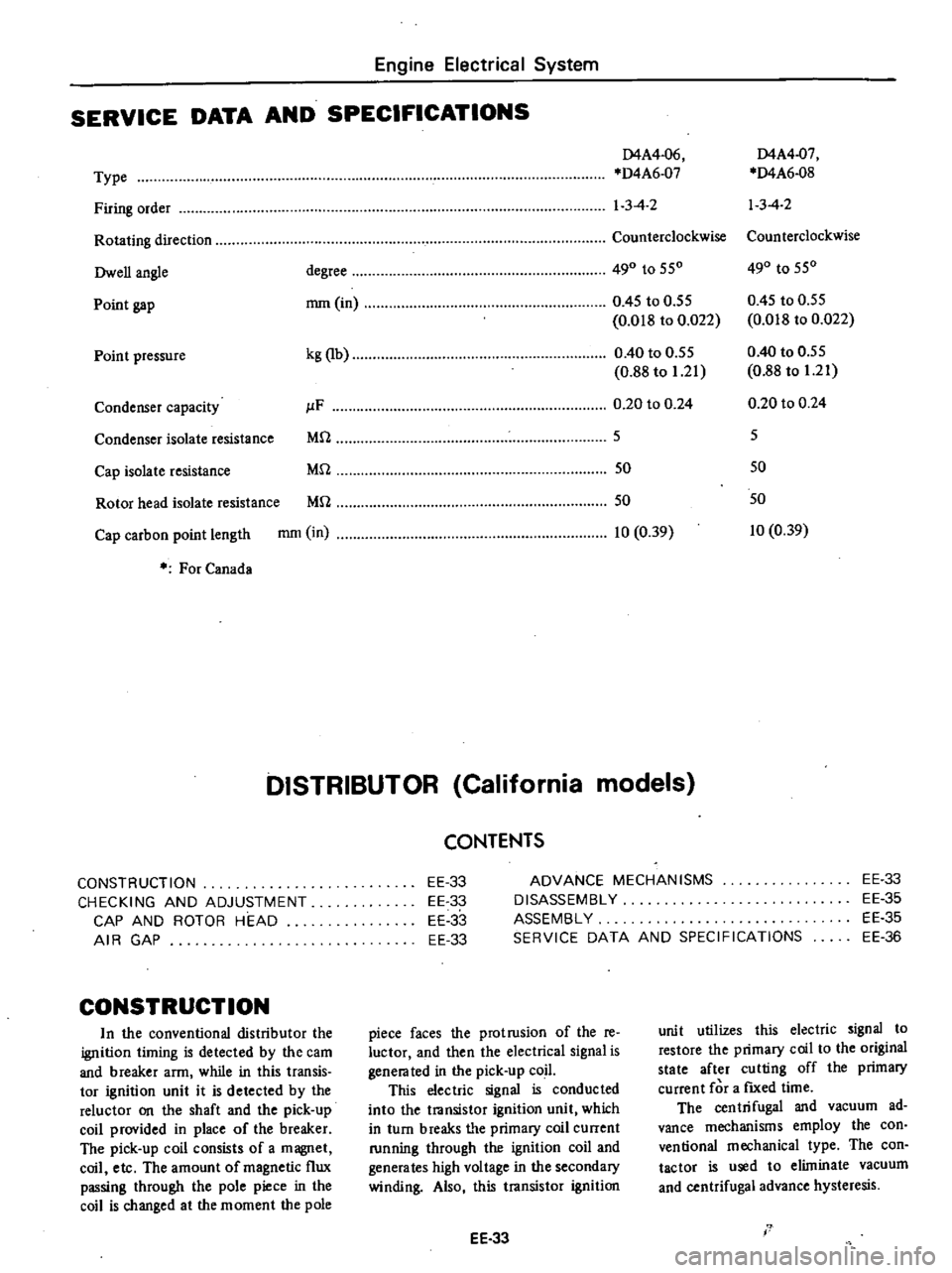
SERVICE
DATA
AND
SPECIFICATIONS
D4A4
06
D4A4
07
Type
D4A6
07
D4A6
08
Firing
order
1
3
4
2
13
4
2
Rotating
direction
Counterclockwise
Counterclockwise
Owen
angle
degree
490
to
550
490
to
550
Point
gap
mm
in
0
45
to
0
55
0
45
to
0
55
0
018
to
0
022
0
018
to
0
022
Point
pressure
kg
lb
0
40
to
0
55
0
40
to
0
55
0
88
to
1
21
0
88
to
1
21
Condenser
capacity
JlF
0
20
to
0
24
0
20
to
0
24
Condenser
isolate
resistance
Mrl
5
5
Cap
isolate
resistance
Mrl
50
50
Rotor
head
isolate
resistance
Mrl
50
50
Cap
carbon
point
length
mm
in
10
0
39
10
0
39
For
Canada
DISTRIBUTOR
California
models
CONSTRUCTION
CHECKING
AND
ADJUSTMENT
CAP
AND
ROTOR
HEAD
AIR
GAP
CONSTRUCTION
In
the
conventional
distributor
the
ignition
liming
is
detected
by
the
cam
and
breaker
arm
while
in
this
transis
tor
ignition
unit
it
is
detected
by
the
reluctor
on
the
shaft
and
the
pick
up
coil
provided
in
place
of
the
breaker
The
pick
up
coil
consists
of
a
magnet
coil
etc
The
amount
of
magnetic
flux
passing
through
the
pole
piece
in
the
coil
is
changed
at
the
moment
the
pole
CONTENTS
EE
33
EE
33
EE
33
EE
33
ADVANCE
MECHANISMS
DISASSEMBLY
ASSEMBLY
SERVICE
DATA
AND
SPECIFICATIONS
EE
33
EE
35
EE
35
EE
36
piece
faces
the
protrusion
of
the
re
luctor
and
then
the
electrical
signal
is
genera
ted
in
the
pick
up
coil
This
electric
signal
is
conducted
into
the
transistor
ignition
unit
which
in
turn
breaks
tI
e
primary
coil
current
running
through
the
ignition
coil
and
generates
high
voltage
in
the
secondary
winding
Also
this
transistor
ignition
EE
33
unit
utilizes
this
electric
signal
to
restore
the
primary
coil
to
the
original
state
after
cutting
off
the
primary
current
for
a
fIXed
time
The
centrifugal
and
vacuum
ad
vance
mechanisms
employ
the
con
ventional
mechanical
type
The
con
tactor
is
used
to
eliminate
vacuum
and
centrifugal
advance
hysteresis
I
Page 201 of 537

t3
l
l
J
@
r
9
V
fW
@
@
CHECKING
AND
ADJUSTMENT
CAP
AND
ROTOR
HEAD
Cap
and
rotor
head
must
be
in
spected
periodically
as
specified
in
the
Maintenance
Schedule
Remove
cap
and
clean
all
dust
and
carbon
deposits
from
cap
and
rotor
from
time
to
time
If
cap
is
cracked
or
is
leaking
replace
with
a
new
one
AIR
GAP
Standard
air
gap
is
0
2
to
0
4
mm
0
008
to
0
016
in
If
the
gap
is
off
the
standard
adjustment
mould
be
made
by
loos
ening
pick
up
coil
screws
Gap
gauge
is
required
for
adjust
ment
Air
gaps
must
be
checked
from
time
to
time
Air
gap
0
2
to
0
4
mm
0
008
to
0
016
in
Engine
Electrical
System
tl
@
9
EE328
Fig
EE
67
Checking
oir
gap
To
remove
pick
up
cail
disconnect
distributor
harness
at
terminal
block
and
remove
screw
securing
pick
up
coil
ADVANCE
MECHANISMS
Specifications
Type
Item
Vacuum
advance
Distributor
degrees
Distributor
mmHg
inHg
Centrifugal
advance
Distributor
degrees
Distributor
cpm
EE34
1
Cap
assembly
2
Rotor
head
a55embly
3
Roll
pin
4
ReJuctor
S
Pick
up
coil
6
Contactoi
7
Breaker
plate
assembly
8
Packing
9
Rotor
shaft
10
Governor
spring
11
Governor
weigh
t
12
Shaft
a
Jscmbly
13
Cap
setter
14
Vacuum
controller
15
Housing
16
Fixing
plate
17
O
ring
18
Collar
EE327
Fig
EE
66
Exploded
view
of
di3tributor
assembly
and
distributor
harness
to
their
positions
EE329
Fig
EE
68
Remouing
pick
up
coil
D4F4
04
D4F4
Q3
Manual
Automatic
00
150
5
91
30
250
9
84
00
550
110
2
300
00
600
110
1
950
Page 204 of 537
Engine
Electrical
System
Transistor
ignition
unit
r
1
Power
switching
circuit
Duty
control
circuit
To
starter
To
distributor
Ba
ttery
Ignition
coil
1
Spark
timing
1
Signal
mom
toring
circuit
Lock
j
preven
ling
circuit
nm
Distributor
EE437
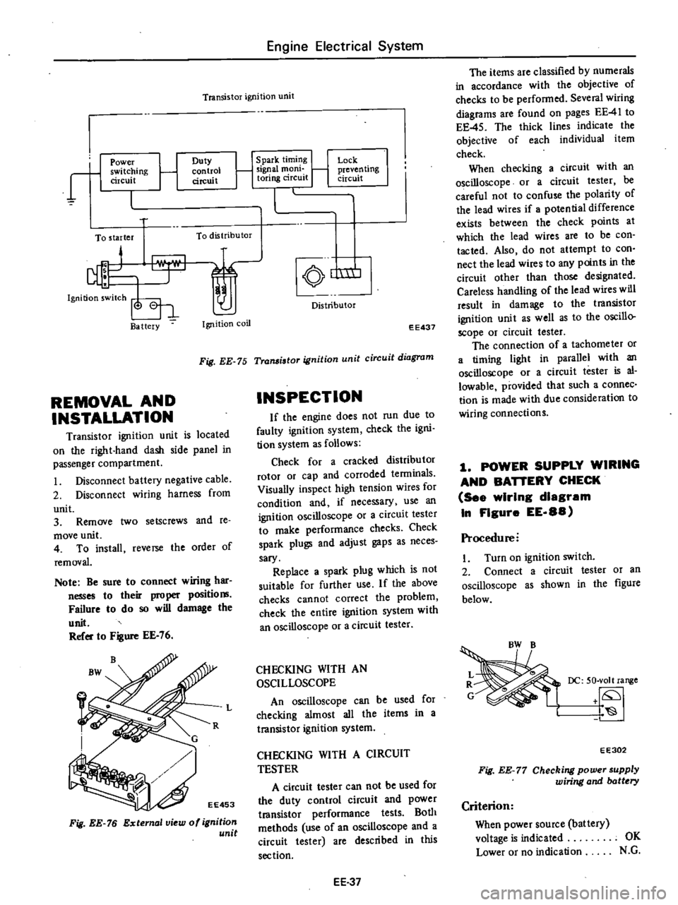
Fig
EE
75
Transistor
ignition
unit
circuit
diagram
REMOVAL
AND
INSTALLATION
Transistor
ignition
unit
is
located
on
the
right
hand
dash
side
panel
in
passenger
compartment
Disconnect
battery
negative
cable
2
Disconnect
wiring
harness
from
unit
3
Remove
two
setscrews
and
te
move
unit
4
To
install
reverse
the
order
of
removal
Note
Be
sure
to
connect
wiring
har
nesses
to
their
proper
positio
Failure
to
do
so
will
damage
the
unit
Refer
to
Figure
EE
76
Fig
EE
76
External
view
of
ignition
unit
INSPECTION
If
the
engine
does
not
run
due
to
faulty
ignition
system
check
the
igni
tion
system
as
follows
Check
for
a
cracked
distributor
rotor
or
cap
and
corroded
tenninals
Visually
inspect
high
tension
wires
for
condition
and
if
necessary
use
an
ignition
oscilloscope
or
a
circuit
tester
to
make
performance
checks
Check
spark
plugs
and
adjust
gaps
as
neces
sary
Replace
a
spark
plug
which
is
not
suitable
for
further
use
If
the
above
checks
cannot
correct
the
problem
check
the
entire
ignition
system
with
an
oscilloscope
or
a
circuit
tester
L
CHECKING
WITH
AN
OSCILLOSCOPE
An
oscilloscope
can
be
used
for
checking
almost
all
the
items
in
a
transistor
ignition
system
CHECKING
WITH
A
CIRCUIT
TESTER
A
circuit
tester
can
not
be
used
for
the
duty
control
circuit
and
power
t18nsistor
performance
tests
Both
methods
use
of
an
oscilloscope
and
a
circuit
tester
are
described
in
this
section
EE
37
The
items
are
classified
by
numerals
in
accordance
with
the
objective
of
checks
to
be
performed
Several
wiring
diagrams
are
found
on
pages
EE
41
to
EE
45
The
thick
lines
indicate
the
objective
of
each
individual
item
check
When
checking
a
circuit
with
an
oscilloscope
or
a
circuit
tester
be
careful
not
to
confuse
the
polarity
of
the
lead
wires
if
potential
difference
exists
between
the
check
points
at
which
the
lead
wires
are
to
be
con
tacted
Also
do
not
attempt
to
con
nect
the
lead
wires
to
any
points
in
the
circuit
other
than
those
designated
Careless
handling
of
the
lead
wires
will
result
in
damage
to
the
transistor
ignition
unit
as
well
as
to
the
oscillo
scope
or
circuit
tester
The
connection
of
a
tachometer
or
a
timing
light
in
parallel
with
an
oscilloscope
or
a
circuit
tester
is
al
lowable
provided
that
such
a
connec
tion
is
made
with
due
consideration
to
wiring
connections
1
POWER
SUPPLY
WIRING
AND
BAnERY
CHECK
See
wIrIng
diagram
In
FIgure
EE
88
Procedure
I
Turn
on
ignition
switch
2
Connect
a
circuit
tester
or
an
oscilloscope
as
shown
in
the
figure
below
DC
50
volt
range
EE302
Fig
EE
77
Checking
power
supply
wiring
and
batt
ry
Criterion
When
power
source
battery
voltage
is
indicated
OK
Lower
or
no
indication
N
G
Page 205 of 537
If
the
result
is
N
C
Take
the
following
measures
I
Check
BW
and
B
color
wire
harness
respectively
for
proper
con
ductance
2
Check
battery
terminals
for
proper
connection
3
Check
charge
condition
of
bat
tery
if
an
excessively
low
voltage
is
indicated
2
CONTINUITY
CHECK
OF
PRIMARY
CIRCUIT
2
1
CheckIng
prImary
circuit
See
wiring
diagram
In
Fig
EE
89
Proced
ure
I
Disconnect
L
color
wire
from
ignition
unit
2
Turn
on
ignition
switch
3
C
ooneet
a
cireui
t
tester
or
an
oscilloscope
as
shown
in
Figure
EE
78
DC
50
volt
range
tf
S
EE303
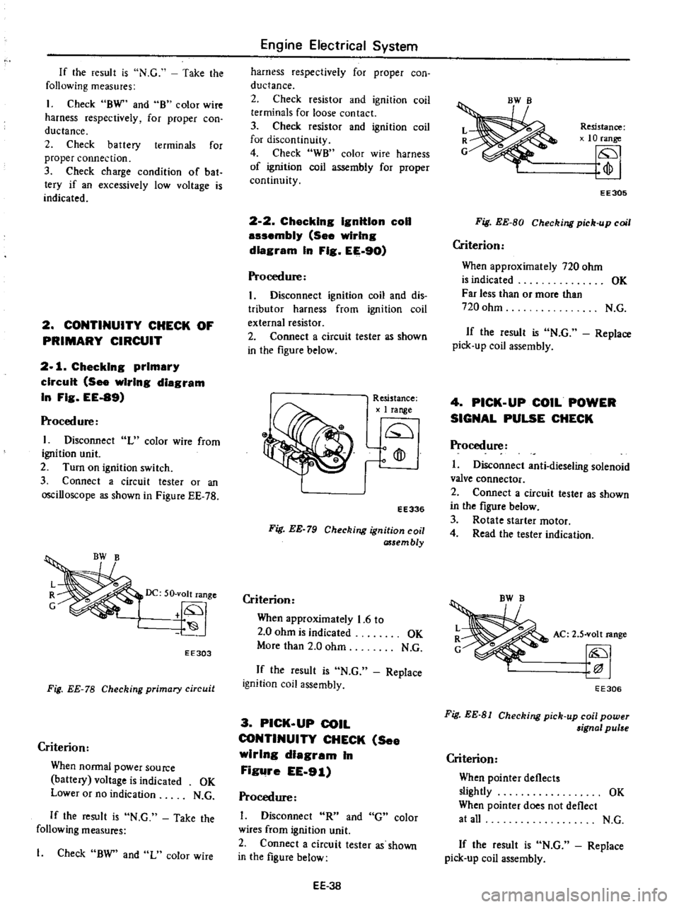
Fig
EE
78
Checking
primary
circuit
Criterion
When
Donnal
power
Source
battery
voltage
is
indicated
OK
Lower
or
no
indication
N
G
If
the
result
is
N
C
Take
the
following
measures
1
Check
BW
and
L
color
wire
Engine
Electrical
System
harness
respectively
for
proper
con
ductance
2
Check
resistor
and
ignition
coil
terminals
for
loose
contact
3
Check
resistor
and
ignition
coil
for
discontinuity
4
Check
WB
color
wire
harness
of
ignition
coil
assembly
for
proper
continuity
2
2
Chacklng
IgnitIon
coil
auembly
See
wiring
diagram
In
Fig
EE
90
Procedure
I
Disconnect
ignition
coil
and
dis
tributor
harness
from
ignition
coil
external
resistor
2
Connect
a
circuit
tester
as
shown
in
the
figure
below
Resistance
1
range
Q
o
fD
ro
EE336
Fig
EE
79
Checking
ignition
coil
assembly
Criterion
When
approximately
1
6
to
2
0
ohm
is
indicated
OK
More
than
2
0
ohm
N
C
If
the
result
is
N
C
Replace
ignition
coil
assembly
3
PICK
UP
COIL
CONTINUITY
CHECK
See
wirIng
dIagram
In
Figure
EE
91
Procedure
Disconnect
R
and
G
color
wires
from
ignition
unit
2
Connect
a
circuit
tester
as
shown
in
the
figure
below
EE
3B
Resistance
10
range
fp
EE305
Fig
EE
BO
Checking
pick
up
coil
Criterion
When
approximately
720
ohm
is
indicated
OK
Far
less
than
or
more
than
720
ohm
N
C
If
the
result
is
N
C
Replace
pick
up
coil
assembly
4
PICK
UP
COIL
POWER
SIGNAL
PULSE
CHECK
Procedure
I
Disconnect
anti
dieseling
solenoid
valve
connector
2
Connect
a
circuit
tester
as
shown
in
the
figure
below
3
Rotate
starter
motor
4
Read
the
tester
indication
AC
2
S
volt
range
EE306
Fig
EE
81
Checking
pick
up
coil
power
aignal
pulse
Criterion
When
pointer
deflects
slightly
OK
When
pointer
does
not
deflect
at
all
N
C
If
the
result
is
N
C
Replace
pick
up
coil
assembly
Page 206 of 537
Procedure
with
an
oscilloscope
1
Disconnect
anti
dieseling
solenoid
valve
connector
2
Connect
a
positive
lead
of
an
oscilloscope
to
R
olor
wire
and
a
negative
lead
of
an
oscilloscope
to
G
color
wire
3
Set
a
SLOPE
select
switch
of
an
oscilloscope
to
the
positive
side
If
so
equipped
4
Rotate
starter
motor
5
Check
the
wave
form
as
shown
in
the
figure
below
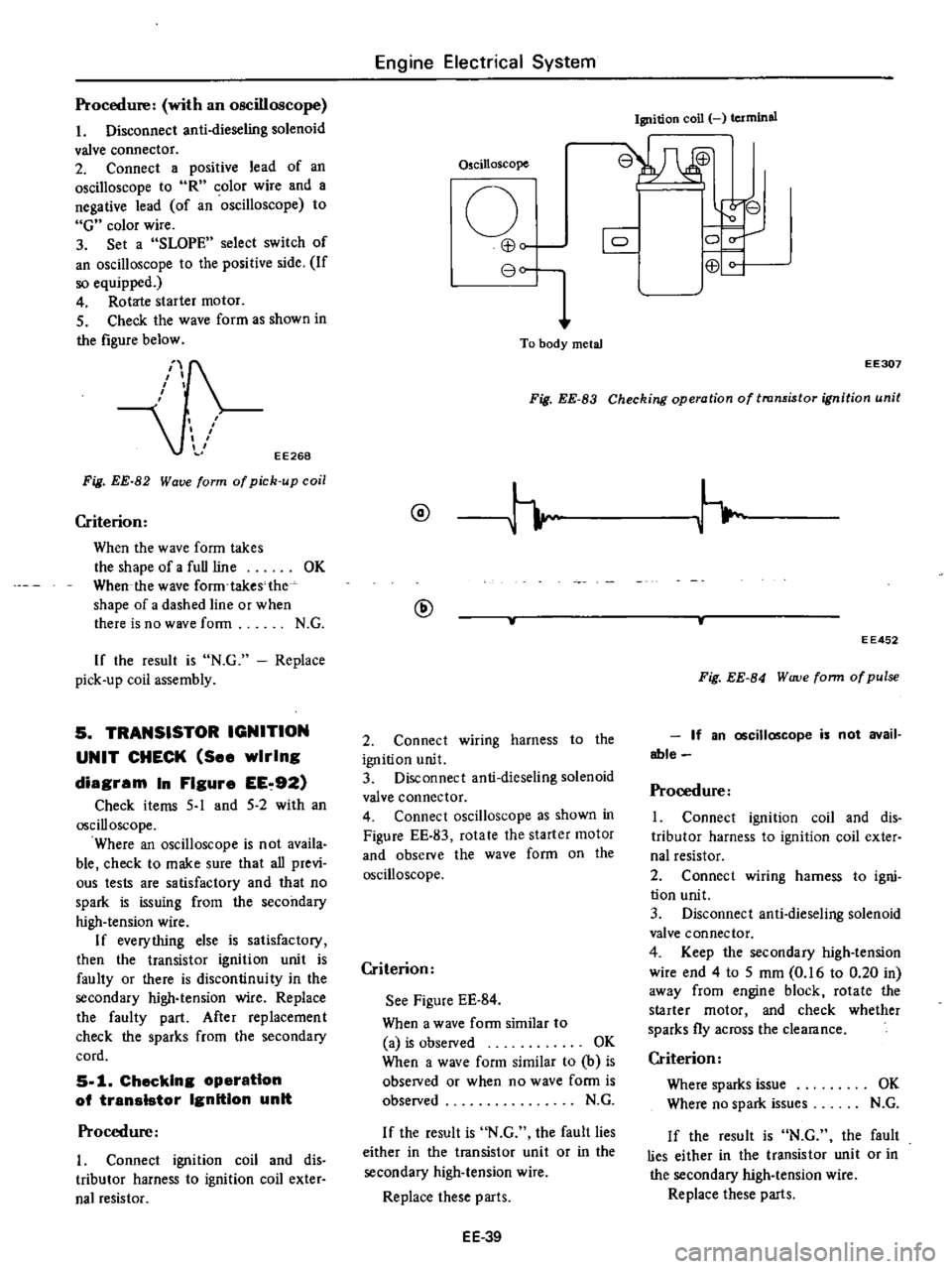
EE268
Fig
EE
82
Wave
form
of
pick
up
coil
Criterion
When
the
wave
form
takes
the
shape
of
a
full
line
OK
When
the
wave
form
takes
the
shape
of
a
dashed
line
or
when
there
is
no
wave
form
N
G
If
the
result
is
N
G
Replace
pick
up
coil
assembly
5
TRANSISTOR
IGNITION
UNIT
CHECK
See
wiring
diagram
In
Figure
EE
92
Check
items
5
1
and
5
2
with
an
oscilloscope
Where
an
oscilloscope
is
not
availa
ble
check
to
make
sure
that
all
previ
ous
tests
are
satisfactory
and
that
no
spark
is
issuing
from
the
secondary
high
tension
wire
If
everything
else
is
satisfactory
then
the
transistor
ignition
unit
is
faulty
or
there
is
discontinuity
in
the
secondary
high
tension
wire
Replace
the
faulty
part
After
replacement
check
the
sparks
from
the
secondary
cord
5
1
Checking
operatIon
of
transIstor
Ignition
unit
Procedure
I
Connect
ignition
coil
and
dis
tributor
harness
to
ignition
coil
exter
nal
resistor
Engine
Electrical
System
Oscilloscope
o
EB
80
To
body
metal
Ignition
coil
terminal
8W
r
8
0
C
0
EB
Fig
EE
83
Checking
operation
of
transistor
ignition
unit
EE307
@
@
2
Connect
wiring
harness
to
the
ignition
unit
3
Disconnect
anti
dieseling
solenoid
valve
connector
4
Connect
oscilloscope
as
shown
in
Figure
EE
83
rotate
the
starter
motor
and
observe
the
wave
form
on
the
oscilloscope
Criterion
See
Figure
EE
84
When
a
wave
form
similar
to
a
is
observed
OK
When
a
wave
form
similar
to
b
is
obseIVed
or
when
no
wave
form
is
observed
N
G
If
the
result
is
N
G
the
fault
lies
either
in
the
transistor
unit
or
in
the
secondary
high
tension
wire
Replace
these
parts
EE
39
EE452
Fig
EE
84
W
uve
form
of
pulse
If
an
oscilloscope
is
not
avail
able
Procedure
1
Connect
ignition
coil
and
dis
tributor
harness
to
ignition
coil
exter
nal
resistor
2
Connect
wiring
harness
to
igni
tion
unit
3
Disconnect
anti
dieseling
solenoid
valve
connector
4
Keep
the
secondary
high
tension
wire
end
4
to
5
mm
0
16
to
0
20
in
away
from
engine
block
rotate
the
starter
motor
and
check
whether
sparks
fly
across
the
clearance
Criterion
Where
sparks
issue
OK
Where
no
spark
issues
N
G
If
the
result
is
N
G
the
fault
lies
either
in
the
transistor
unit
or
in
the
secondary
high
tension
wire
Replace
these
paris
Page 215 of 537
Engine
Electrical
System
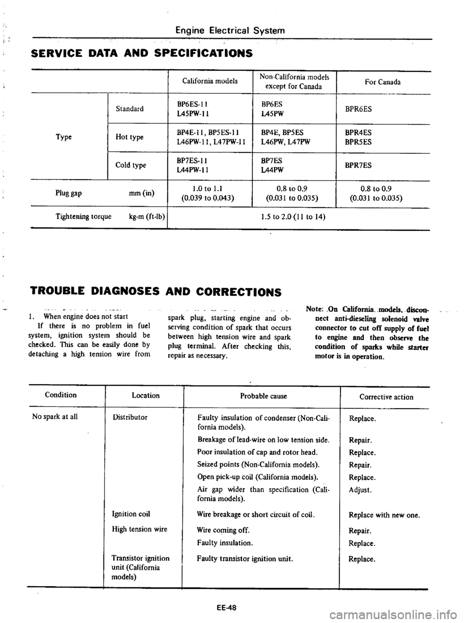
SERVICE
DATA
AND
SPECIFICATIONS
California
models
Non
California
models
For
Canada
except
for
Canada
BP6ES
ll
BP6ES
BPR6ES
Standard
L45PW
ll
L45PW
BP4E
ll
BP5ES
ll
BP4E
BP5ES
BPR4ES
Type
Hot
type
L46PW
ll
L47PW
ll
L46PW
L47PW
BPR5ES
Cold
type
BP7ES
ll
BP7ES
BPR7ES
LMPW
ll
LMPW
1
0
to
l
l
0
8
to
0
9
0
8
to
0
9
Plug
gap
mm
in
0
039
to
0
043
0
031
to
0
D35
0
031
to
0
035
Tightening
torque
kg
m
ft
Ib
I
1
5
to
2
0
11
to
14
TROUBLE
DIAGNOSES
AND
CORRECTIONS
When
engine
does
not
start
If
there
is
no
problem
in
fuel
system
ignition
system
should
be
checked
This
can
be
easily
done
by
detaching
a
high
tension
wire
from
spark
plug
starting
engine
and
ob
serving
condition
of
spark
that
occurs
between
high
tension
wire
and
spark
plug
terminal
After
checking
this
repair
as
necessary
Note
On
California
models
disc
on
nect
anti
dieseling
solenoid
valve
connector
to
cut
off
supply
of
fuel
to
engine
and
then
observe
the
condition
of
spaIks
while
starter
motor
is
in
operation
Condition
Location
Probable
cause
Corrective
action
No
spark
at
all
Distributor
Faulty
insulation
of
condenser
Non
Cali
Replace
fomia
models
Breakage
of
lead
wire
on
low
tension
side
Repair
Poor
insulation
of
cap
and
rotor
head
Replace
Seized
points
Non
California
models
Repair
Open
pick
up
coil
California
models
Replace
Air
gap
wider
than
specification
Cali
Adjust
fornia
models
Ignition
coil
Wire
breakage
or
short
circuit
of
coil
Replace
with
new
one
High
tension
wire
Wire
coming
off
Repair
Faulty
insulation
Replace
Transistor
ignition
Faulty
transistor
ignition
unit
Replace
unit
California
models
EE
4B
Page 268 of 537
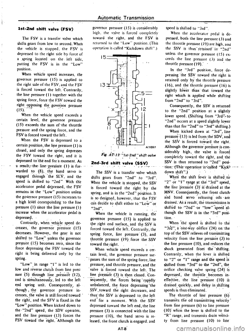
1st
2nd
shift
valve
FSV
The
FSV
is
a
transfer
valve
which
shifts
gears
from
low
to
second
When
Ihe
vehicle
is
stopped
the
FSV
is
depressed
to
the
right
side
by
force
of
a
spring
located
on
the
left
side
putting
the
FSV
is
in
the
low
position
When
vehicle
speed
increases
the
governor
pressure
15
is
applied
to
Ihe
right
side
of
the
FSV
and
the
FSV
is
forced
toward
the
left
Contrarily
the
line
pressure
I
togelher
with
the
spring
force
force
the
FSV
toward
the
right
opposing
the
governor
pressure
15
When
the
vehide
speed
exceeds
a
certain
level
the
governor
pressure
15
exceeds
the
sum
of
the
throttle
pressure
and
Ihe
spring
force
and
the
FSV
is
forced
toward
the
left
When
the
FSV
is
depressed
10
a
certain
position
the
lire
pressure
I
is
closed
and
only
the
spring
depresses
the
FSV
toward
the
right
and
it
is
depressed
to
the
end
for
a
moment
As
a
resull
the
line
p
ressure
lJ
is
for
warded
to
8
the
band
servo
is
engaged
through
the
SLY
and
the
speed
is
shifted
to
2nd
With
the
accelerator
pedal
depressed
the
FSV
remains
iIi
the
Low
position
unless
the
governor
pressure
IS
increases
to
a
high
leVel
corresponding
to
the
line
pressure
I
since
the
line
pressure
I
increase
when
the
accelerator
pedal
is
depresse9
Contrarily
when
vehicle
speed
de
creases
the
governor
pressure
15
decrease
Howeve
f
the
gear
is
not
shifted
to
Low
nless
the
governor
pressure
15
becomes
zero
since
the
force
depressing
the
FSV
toward
the
right
is
being
delivered
only
by
the
spring
Low
in
range
I
is
led
to
the
low
and
reverse
clutch
from
line
pres
sure
5
through
line
prbssure
12
2nd
is
simultaneousi
y
led
to
the
ieft
end
spring
unit
Consequently
al
thougp
the
goverflor
pressure
in
creases
the
valve
is
still
forced
toward
the
right
and
the
SFV
is
fixedjn
the
Low
position
When
kicked
down
to
the
2nd
speed
the
SDV
operates
and
the
line
pressure
13
forces
the
FSV
toward
the
right
Although
the
Automatic
Transmission
governor
pressure
15
is
considerably
high
the
valve
is
forced
completely
toward
the
right
and
the
FSV
is
returned
to
the
Low
position
This
operation
is
alled
Kickdown
shift
15
j
13
1
c5
I
0
t
r
I
I
q
1
AT091
Fig
AT
12
lsl
2nd
shift
valve
2nd
3rd
shift
valve
SSV
The
SSV
is
a
transfer
valve
which
shifts
gears
from
2nd
to
3rd
When
the
vehicle
is
stopped
the
SSV
is
forced
toward
the
right
by
the
spring
and
is
in
the
2nd
position
It
is
so
design
d
however
that
the
FSV
can
decide
to
shift
either
to
Low
or
2nd
When
the
vehicle
is
running
the
governor
pressure
15
is
applied
to
the
right
end
surface
and
th
SSV
is
forced
toward
the
left
Contrarily
the
Spri
l
force
line
pressure
3
and
throttle
press
re
19
force
the
SSV
toward
the
right
When
vehicle
speed
exceeds
a
cee
tain
level
the
governor
pressure
sur
passes
the
sum
of
the
spring
force
line
pressure
and
throttle
pressure
and
the
valve
is
forced
toward
the
left
The
line
pressure
3
is
then
closed
Con
sequently
the
forces
being
rapjdly
unbalanced
the
force
depressing
the
SSV
toward
the
right
decreases
and
thus
the
SSV
is
depressed
to
the
l
ft
end
for
a
moment
With
Ihe
SSV
depressed
toward
the
left
end
lhe
line
pressure
3
is
connected
with
the
line
pressure
10
the
band
servo
is
re
leased
the
front
clutch
is
engaged
and
AT
8
speed
is
shifted
to
3rd
When
the
accelerator
pedJI
is
de
prcssed
both
the
line
pressure
3
and
the
throttle
pressure
19
are
high
allll
the
SSV
is
thus
retained
in
nd
unless
the
governor
pressure
15
ex
ceeds
the
line
pressure
3
and
the
throttle
pressure
19
In
the
3rd
position
force
de
pressing
ihe
SSV
toward
the
right
is
retained
only
by
the
throttle
pressure
16
and
the
throttle
pressure
16
is
slightly
Idwer
than
that
toward
the
right
which
is
applied
while
shifting
from
2nd
to
3rd
Consequently
the
SSV
is
returned
to
the
2nd
position
at
a
slightly
lower
speed
Shifting
from
3rd
to
2nd
occurs
at
a
speed
slightly
lower
than
that
for
2nd
to
3rd
shifting
When
kicked
down
at
3rd
line
pressure
13
is
led
from
the
SDV
and
the
SSV
is
forced
toward
the
right
Although
the
governor
pres
ure
is
con
siderably
high
the
valve
is
forced
completely
loward
the
right
and
tht
SSV
is
thus
returned
to
2nd
posi
tion
fhis
operation
is
called
K
cli
down
shift
When
the
shift
iever
is
shifted
to
2
or
I
range
at
the
3rd
speed
the
line
pressure
3
if
diained
at
the
MNV
Consequently
the
front
clutch
and
band
servo
releasing
oils
are
drained
As
a
result
the
transmission
is
shifted
to
2nd
or
low
speed
ai
though
the
SSV
is
in
the
3rd
posi
tion
When
the
specd
IS
shifted
io
the
3r
1
a
one
way
orifice
24
on
the
topof
the
SSV
relieves
oil
transmitting
velocity
from
the
line
pressure
3
to
the
line
pressure
10
and
reduces
the
shock
generated
fioni
the
shifting
Contrarily
when
the
lever
is
shifted
to
2
or
I
range
and
the
speed
is
shifted
from
3rd
to
the
2nd
the
orifice
checking
valve
spring
24
is
depressed
the
throttle
becomes
in
effective
the
line
pressure
10
is
drained
quickly
and
delay
in
shifting
speeds
is
thus
eliminated
The
throttle
of
line
pressure
6
transmits
Hie
oil
transmitting
velocity
from
line
pressure
6
to
line
pressurc
10
wtien
the
lever
is
shifted
to
the
R
range
and
transmits
drain
veloci
ty
from
line
pressure
10
to
line
Page 298 of 537
Starter
should
be
brought
into
op
eration
only
when
selector
lever
is
in
P
and
N
positions
it
should
not
be
started
when
lever
is
in
D
2
I
and
R
positions
Back
up
lamp
should
also
light
when
selector
lever
is
placed
in
R
position
S
After
converter
is
installed
rotate
10
Check
level
of
oil
in
transmis
crankshaft
several
turns
and
check
to
be
sure
that
transmission
rotates
freely
sion
For
detailed
procedure
see
page
AT48
without
binding
6
Pour
recommended
automatic
II
Move
selector
lever
through
aU
positions
to
be
sure
that
transmission
transmission
fluid
up
to
correct
level
operates
correctly
through
oil
charge
pipe
verter
to
transmission
measure
dis
With
hand
brake
applied
rotate
tan
A
to
be
certain
that
they
are
7
Connect
manual
lever
to
shift
engine
at
idling
Without
disturbing
correctly
mbi
d
S
F
rod
Opeiationsliould
oecaTrie
f
bue
the
above
sclUng
ffiovTSelector
lever
AT
50
with
manual
and
selector
levers
in
through
N
to
D
to
2
to
I
Distance
A
N
and
to
R
A
slight
shock
should
be
More
than
21
5
mm
0
846
in
8
Connect
inhibitor
switch
wires
felt
by
hand
gripping
selector
each
time
transmission
is
shifted
Automatic
Transmission
4
Bolt
converter
to
drive
plate
Note
Align
chalk
marks
painted
a
cross
both
parts
during
disas
sembling
processes
AT116
Fig
AT
49
Torque
converter
aligning
cu
t
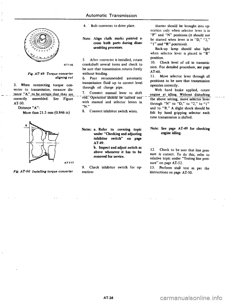
3
When
connecting
torque
can
A
ATl17
Notes
a
Refer
to
covering
topic
under
Checking
and
adjusting
inhibitor
switch
n
on
page
AT
49
b
Inspect
and
adjust
switch
as
above
whenever
it
has
to
be
removed
for
service
Fig
AT
50
Installing
torque
converter
9
Check
inhibitor
switch
for
op
eration
AT
34
Note
See
page
AT
49
for
checking
engine
idling
12
Check
to
be
sure
that
line
pres
sure
is
correct
To
do
this
refer
to
relative
topic
under
Testing
line
pres
sure
on
page
AT
52
13
Perform
stall
test
as
per
the
instructions
on
page
AT
50
Page 312 of 537
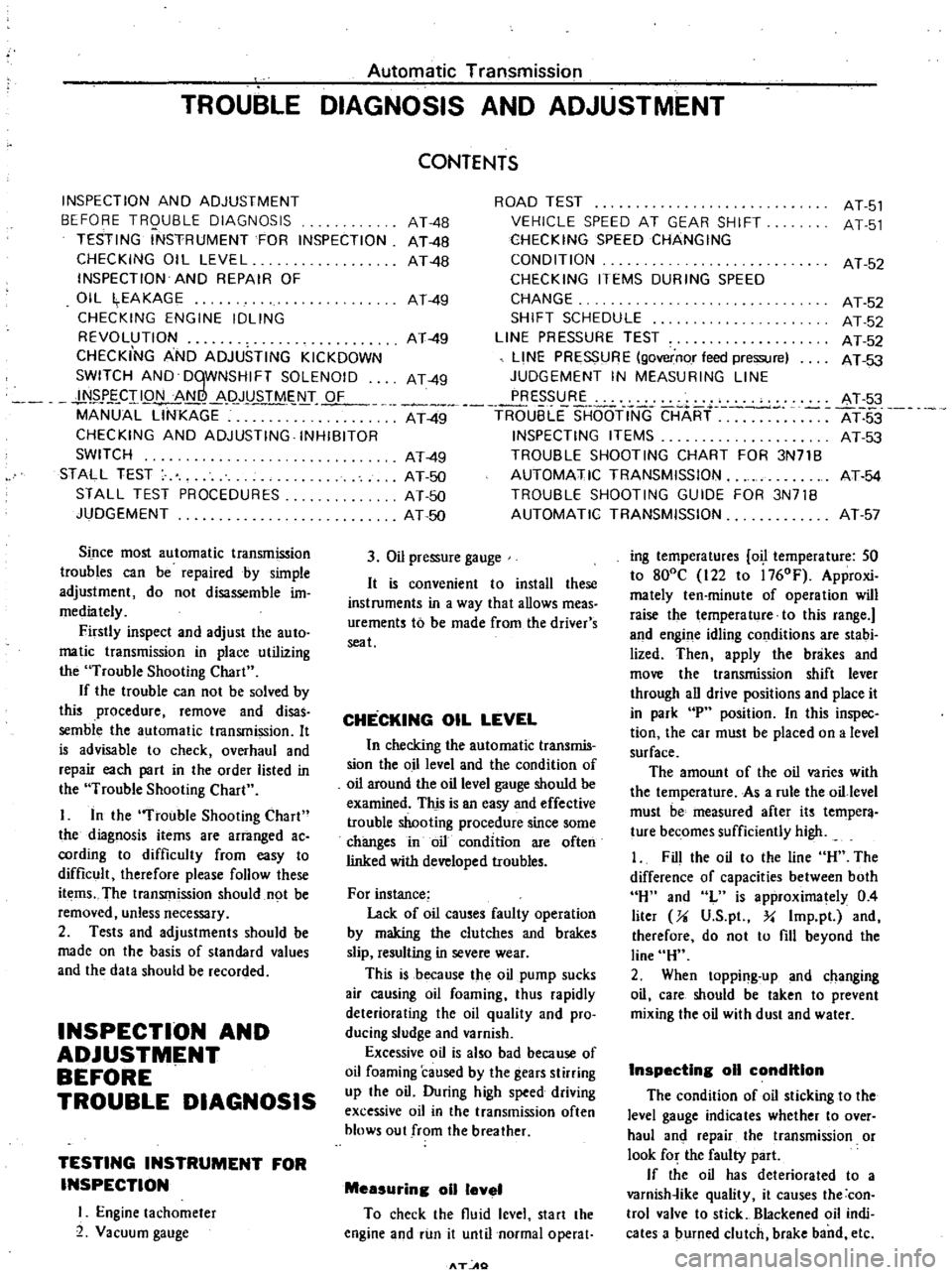
Automatic
Transmission
TROUBLE
DIAGNOSIS
AND
ADJUSTMENT
INSPECTION
AND
ADJUSTMENT
BEFORE
TRQUBLE
DIAGNOSIS
TESTING
INSTRUMENT
FOR
INSPECTION
CHECKING
OIL
LEVEL
INSPECTION
AND
REPAIR
OF
OIL
EAKAGE
CHECKING
ENGINE
IDLING
REVOLUTION
CHECKING
AND
ADJUSTING
KICKDOWN
SWITCH
AND
DqWNSHIFT
SOLENOID
N
J
J
CII
Q
t
L
8li
p
JYSTMs
T
OF
MANUAL
LINKAGE
CHECKING
AND
ADJUSTING
INHIBITOR
SWITCH
STALL
TEST
STALL
TEST
PROCEDURES
JUDGEMENT
Since
most
automatic
transmission
troubles
can
be
repaired
by
simple
adjustment
do
not
disassemble
im
mediately
Firstly
inspect
and
adjust
the
auto
matic
transmission
in
place
utilizing
the
Trouble
Shooting
Chart
If
the
trouble
can
not
be
solved
by
this
procedure
remove
and
disas
semble
the
automatic
transmission
It
is
advisable
to
check
overhaul
and
repair
each
part
in
the
order
listed
in
the
Trouble
Shooting
Chart
I
In
the
Trouble
Shooting
Chart
the
diagnosis
items
are
arranged
ac
cording
to
difficulty
from
easy
to
difficult
therefore
please
follow
these
items
The
transmission
should
not
be
removed
unless
necessary
2
Tests
and
adjustments
should
be
made
on
the
basis
of
standard
values
and
the
data
should
be
recorded
INSPECTION
AND
ADJUSTMENT
BEFORE
TROUBLE
DIAGNOSIS
TESTING
INSTRUMENT
FOR
INSPECTION
I
Engine
tachometer
2
Vacuum
gauge
ROAD
TEST
VEHICLE
SPEED
AT
GEAR
SHIFT
CHECKING
SPEED
CHANGING
CONDITION
CHECKING
ITEMS
DURING
SPEED
CHANGE
SHIFT
SCHEDULE
LINE
PRESSURE
TEST
LINE
PRESSURE
governor
feed
pressure
JUDGEMENT
IN
MEASURING
LINE
PRESSURE
At
49
TR6
uBLE
SHOOTINC
CHART
INSPECTING
ITEMS
TROUBLE
SHOOTING
CHART
FOR
3N71B
AUTOMATIC
TRANSMISSION
TROUBLE
SHOOTING
GUIDE
FOR
3N71B
AUTOMATIC
TRANSMISSION
CONTENTS
AT
4B
AT
48
AT
4B
AT
49
AT
49
AT
49
AT
49
AT
50
AT
50
AT
50
3
Oil
pressure
gauge
It
is
convenient
to
install
these
instruments
in
a
way
that
allows
meas
urements
to
be
made
from
the
driver
s
seat
CHECKING
OIL
LEVEL
In
checking
the
automatic
transmis
sion
the
o
illevel
and
the
condition
of
oil
around
the
oil
level
gauge
should
be
examined
This
is
an
easy
and
effective
trouble
shooting
procedure
since
some
changes
in
oil
condition
are
often
linked
with
developed
troubles
For
instance
Lack
of
oil
causes
faulty
operation
by
making
the
clutches
and
brakes
slip
resulting
in
severe
wear
This
is
because
the
oil
pump
sucks
air
causing
oil
foaming
thus
rapidly
deteriorating
the
oil
quality
and
pro
ducing
sludge
and
varnish
Excessive
oil
is
also
bad
because
of
oil
foaming
caused
by
the
gears
stirring
up
the
oil
During
high
speed
driving
excessive
oil
in
the
transmission
often
blows
out
from
the
breather
Measuring
011
level
To
check
the
fluid
level
start
the
engine
and
run
it
until
normal
operat
T
AO
AT
51
AT
51
AT
52
AT
52
AT
52
AT
52
AT
53
AT
3
AT
53
AT
53
AT
54
AT
57
ing
temperatures
o
temperature
SO
to
800C
122
to
l760F
Approxi
mately
ten
minute
of
operation
will
raise
the
temperature
to
this
range
and
engine
idling
conditions
are
stabi
lized
Then
apply
the
brakes
and
move
the
transmission
shift
lever
through
all
drive
positions
and
place
it
in
park
P
position
In
this
inspec
tion
the
car
must
be
placed
on
a
level
surface
The
amount
of
the
oil
varies
with
the
temperature
As
a
rule
the
oil
level
must
be
measured
after
its
temper
ture
becomes
sufficiently
high
1
Fill
the
oil
to
the
line
H
The
difference
of
capacities
between
both
H
and
L
is
approximately
0
4
liter
Ji
V
S
p
Y
Imp
pl
and
therefore
do
not
to
fill
beyond
the
line
H
2
When
topping
up
and
changing
oil
care
should
be
taken
to
prevent
mixing
the
oil
with
dust
and
water
InspectIng
011
condition
The
condition
of
oil
sticking
to
the
level
gauge
indicates
whether
to
over
haul
and
repair
the
transmission
or
look
for
the
faulty
part
If
the
oil
has
deteriorated
to
a
varnish
ike
quality
it
causes
the
con
trol
valve
to
stick
Blackened
oil
indi
cates
a
burned
clutch
brake
band
etc
Page 313 of 537
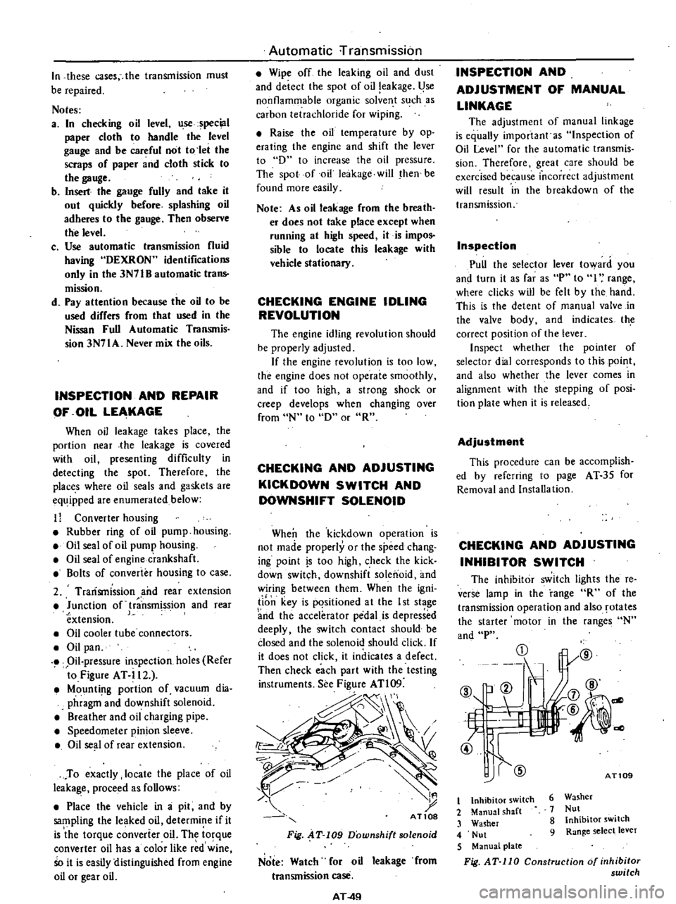
In
these
cases
the
transmission
must
be
repaired
Notes
a
In
checking
oil
level
use
special
paper
cloth
to
handle
the
level
gauge
and
be
careful
not
to
let
the
scraps
of
paper
and
cloth
stick
to
the
gauge
b
Insert
the
gauge
fully
and
take
it
out
quickly
before
splashing
oil
adheres
to
the
gauge
Then
observe
the
level
c
Use
automatic
transmission
fluid
having
DEXRON
identifications
only
in
the
3N71B
automatic
trans
mission
d
Pay
attention
because
the
oil
to
be
used
differs
from
that
used
in
the
Nissan
Full
Automatic
TranSJTIis
sion
3N71A
Never
mix
the
oils
INSPECTION
AND
REPAIR
OF
OIL
LEAKAGE
When
oil
leakage
takes
place
the
portion
near
the
leakage
is
covered
with
oil
presenting
difficulty
in
detecting
the
spot
Therefore
the
places
where
oil
seals
and
gaskets
are
equipped
are
enumerated
below
11
Converter
housing
Rubber
ring
of
oil
pump
housing
Oil
seal
of
oil
pump
housing
Oil
seal
of
engine
crankshaft
Bolts
of
converter
housing
to
case
2
Trarismission
and
rear
extension
Junction
of
transm
ss
ion
and
rear
extension
J
Oil
cooler
tube
connectors
Oil
pan
Oil
pressure
inspection
holes
Refer
to
Figure
AT
il2
Mounting
portion
of
vacuum
dia
phragm
and
downshift
solenoid
Breather
and
oil
charging
pipe
Speedometer
pinion
sleeve
Oil
se
l
of
rear
extension
To
exactly
locate
the
place
of
oil
leaka
le
proceed
as
follows
Place
the
vehicle
in
a
pit
and
by
sampling
the
leaked
oil
determine
if
it
is
the
torque
converter
oil
The
torque
converter
oil
has
a
color
like
r
d
wine
So
it
is
easily
distinguished
from
engine
oil
or
gear
oil
Automatic
rransmission
Wipe
off
the
leaking
oil
and
dust
and
deiecl
the
spol
of
oil
eakage
l
se
nonflammable
organic
solve
t
s
ch
as
carbon
tetrachloride
for
wiping
Raise
the
oil
tcmperalure
by
op
erating
the
engine
and
shift
the
lever
to
D
to
increase
the
oil
pressure
The
spot
of
oil
lcakage
will
then
be
found
more
easily
Note
As
oil
leakage
from
the
breaih
er
does
not
take
place
except
when
running
at
high
speed
it
is
impos
sible
to
locate
this
leakage
with
vehicle
stationary
CHECKING
ENGINE
IDLING
REVOLUTION
The
engine
idling
revolution
should
be
properly
adjusted
If
the
engine
revolution
is
too
low
the
engine
does
not
operate
smoothly
and
if
too
high
a
strong
shock
or
creep
develops
when
changing
over
from
N
to
D
or
R
CHECKING
AND
ADJUSTING
KICK
DOWN
SWITCH
AND
DOWNSHIFT
SOLENOID
When
the
kickdown
operation
is
not
made
properly
or
the
speed
chang
ing
point
s
too
high
check
the
kick
down
switch
downshift
solenoid
and
wiring
between
them
When
the
igni
li
n
key
is
pqsitioned
a
t
the
I
st
stage
nd
the
accelerator
pedal
is
depressed
deeply
the
switch
contact
should
be
closed
and
the
solenoid
should
click
If
it
does
not
click
it
indicates
a
defect
Then
check
each
part
with
the
testing
instruments
See
Figure
ATl09
d
I
t
AT10S
Fig
AT
109
Downshift
solenoid
Note
Watch
for
oil
leakage
from
transmission
case
AT
4Q
INSPECTION
AND
ADJUSTMENT
OF
MANUAL
LINKAGE
The
adjustmcnt
of
manual
linkage
is
equaUy
important
as
Inspection
of
Oil
Level
for
the
automatic
transmis
sion
Thereforc
great
care
should
be
exercised
because
incorrect
adjustment
will
rcsult
in
the
brcakdown
of
the
transmission
Inspection
Pull
the
selector
lever
toward
you
and
turn
it
as
far
as
P
to
I
range
wherc
clicks
will
be
felt
by
the
hand
This
is
the
detcnt
of
manual
valve
in
the
valve
body
and
indicates
th
correct
position
of
the
lever
Inspect
whether
the
pointer
of
selector
dial
corresponds
to
this
point
and
also
whether
the
lever
comes
in
alignment
with
the
stepping
of
posi
tion
plate
when
it
is
released
Adjustment
This
procedure
can
be
accomplish
ed
by
refcrring
to
page
AT
35
for
Removal
and
Installa
tion
CHECKING
AND
ADJUSTING
INHIBITOR
SWITCH
The
inhibitor
switch
lights
the
re
verse
lamp
in
the
range
R
of
the
transmission
operatio
l
and
also
rotates
the
starter
motor
in
the
ranges
N
and
P
CD
@
b
ell
If
L
t
7
4l
@
1l
j7
@
@
@
dl
AT109
6
Washer
7
Nut
8
Inhibitor
switch
9
Range
select
lever
t
Inhibitor
switch
2
Manual
shaft
3
Washer
4
Nut
5
Manual
plate
Fig
AT
110
Construction
of
inhibitor
switch