fuel pressure DATSUN PICK-UP 1977 User Guide
[x] Cancel search | Manufacturer: DATSUN, Model Year: 1977, Model line: PICK-UP, Model: DATSUN PICK-UP 1977Pages: 537, PDF Size: 35.48 MB
Page 106 of 537

4
Run
the
engine
at
varying
speeds
5
The
pressure
gauge
indicates
static
fuel
pressure
in
the
line
The
gauge
reading
should
be
within
the
following
range
0
21
to
0
27
kg
em2
3
0
to
3
8
psi
Note
If
the
fuel
in
carburetor
float
chamber
has
run
out
and
engine
has
stopped
clip
and
pour
fuel
into
carburetor
Fasten
clip
secure
ly
and
repe
1
static
pressure
test
Pressure
below
the
lower
limit
indi
cates
extreme
wear
on
one
part
or
a
small
amount
of
wear
on
each
working
part
It
also
indicates
ruptured
dia
phragm
worn
warped
dirty
or
gum
ming
valves
and
seats
or
a
weak
diaphragm
return
spring
Pressure
above
the
upper
limit
indicates
an
excessively
strong
tension
of
dia
phragm
return
spring
or
a
diaphragm
that
is
too
tight
Both
of
these
condi
tions
require
the
removal
of
pump
assembly
for
replacement
or
repair
CAPACITY
TEST
The
capacity
test
is
made
only
when
static
pressure
is
within
the
specifications
To
make
this
test
pro
ceed
as
follows
1
Disconnect
pressure
gauge
from
T
connector
and
in
its
vacant
place
install
a
suitable
container
as
a
fuel
sump
2
Run
engine
at
1
000
rpm
3
The
pump
should
deliver
1
000
cc
2
11
US
pt
of
fuel
in
one
minute
or
less
If
little
or
no
fuel
flows
from
the
open
end
of
pipe
it
is
an
indication
that
fuel
line
is
clogged
or
pump
is
malfunctioning
REMOVAL
AND
DISASSEMBLY
Remove
fuel
pump
assembly
by
unscrewing
two
mounting
nuts
and
disassemble
in
the
following
order
1
Separate
upper
body
and
lower
body
by
unscrewing
body
set
screws
Engine
Fuel
2
Take
off
cap
and
cap
gasket
by
removing
cap
screws
3
Unscrew
elbow
and
connector
4
Take
off
valve
retainer
by
un
screwing
two
retainer
screws
and
re
move
two
valves
5
To
remove
diaphragm
press
down
its
center
against
spring
force
With
diaphragm
pressed
down
tilt
it
until
the
end
of
pull
rod
touches
the
inne
wall
of
body
Then
release
diaphragm
to
unhook
push
rod
Be
careful
during
this
operation
not
to
damage
diaphragm
or
oil
se
L
i
J
EFOO7
Fig
EF
20
Remouing
pull
rod
6
Drive
rocker
arm
pin
out
with
a
press
or
hammer
8
o
6
7
8
@
INSPECTION
I
Check
upper
body
and
lower
body
for
cracks
EF
10
I
fuel
pump
cap
2
Cap
gasket
3
Valve
packing
4
fuel
pump
val
e
assembly
S
Valve
retainer
6
Diaphragm
assembly
7
Diaphragm
spring
8
PuRro
9
Lower
body
seal
washer
10
Lower
body
seal
11
Inkl
connector
12
Outlet
connector
13
Rocker
arm
spring
14
Rocker
arm
I
S
Rocker
artyl
side
pin
16
Fuel
pump
packing
17
Spacer
fuel
pump
fo
cylinder
block
EF510
Fig
EF
21
Slruc
ure
of
fuel
pump
2
Check
valve
assembly
for
wear
on
valve
and
valve
spring
Blow
valve
assembly
with
brea
th
to
examine
its
function
Page 108 of 537

854
co
in
in
one
minute
or
less
If
no
gasoline
or
only
a
little
flows
from
open
end
of
pipe
with
pump
operated
or
if
pump
does
not
work
perform
the
following
diagnosis
Notes
3
Do
not
connect
battery
in
reverse
polarity
which
if
left
for
a
long
time
would
damage
transitor
circuit
and
disable
pump
Engine
Fuel
b
Do
not
let
fall
pump
as
it
may
damage
electronic
components
c
Do
not
apply
overvoitage
max
l
8Y
Overvoltage
starting
by
quick
charge
or
tage
running
would
deteriorate
or
damage
elec
tronic
components
Fuel
pressure
maximum
0
32
kg
cm
4
6
psi
REMOVAL
AND
INSTALLATION
Flom
fuel
tank
Electric
fuel
pump
is
installed
on
bracket
with
two
bolts
This
bracket
is
located
on
R
H
side
member
adjacent
to
fuel
tank
I
Remove
inlet
hose
from
fuel
pump
Also
remove
outlet
hose
run
ning
to
engine
Receive
fuel
remaining
in
fuel
hose
in
a
suitable
container
2
Disconnect
harness
at
connector
3
Remove
bolts
securing
fuel
pump
to
bracket
and
detach
fuel
pump
4
Installation
is
the
reverse
order
of
removal
9
@
1
Cover
2
Magnet
3
Cover
gasket
4
Filter
5
Gasket
6
Spring
retainer
7
Washer
8
O
ring
9
Inlet
valve
10
Retutn
PIing
11
Plunger
12
Plunger
cylinder
13
Body
To
carburetor
1
Elecuic
fuel
pump
2
Mounting
bracket
3
Fuel
mter
EF72D
Fig
EF
23
Electric
fuel
pump
DISASSEMBLY
Do
not
disassemble
unless
pump
is
faulty
I
Remove
cover
with
wrench
and
take
out
cover
gasket
magnet
and
filter
from
pump
body
2
When
removing
plunger
take
out
spring
retainer
from
plunger
tube
3
Then
take
out
washer
O
ring
inlet
valve
return
spring
and
plunger
from
tube
Note
Do
not
disassemble
electronic
components
If
n
replace
with
new
ones
6
EF721
Fig
EF
24
Exploded
view
of
electric
fuel
pump
EF
12
ASSEMBLY
I
Before
assembly
clean
all
parts
with
gasoline
and
compressed
air
com
pletely
Notes
a
If
gask
t
an
d
fdterare
faulty
r
place
b
Clean
magnet
and
cover
for
fault
c
Take
care
not
to
defonn
thin
tube
d
Assemble
plunger
return
spring
inlet
valve
O
ring
washer
and
set
spring
retainer
in
that
order
e
Assemble
filter
gasket
and
cover
with
f
Tighten
cover
with
wrench
to
the
stopper
If
component
parts
are
dirty
after
disassembly
clean
as
follows
Wash
fIlter
and
strainer
with
clean
gasoline
and
blow
with
compressed
air
When
cleaning
parts
check
fllter
for
fault
If
faulty
replace
Wash
plunger
plunger
cylinder
and
inlet
valve
with
clean
gasoline
and
blow
dust
off
with
compressed
air
2
Check
c
v
m
lI
parts
for
wear
or
damage
If
they
are
found
faulty
replace
them
3
Insert
plunger
assembly
into
plunger
cylinder
of
body
and
apply
electric
current
to
it
Move
the
assembly
up
and
down
If
the
assembly
does
not
move
it
shows
that
the
electric
uuit
is
faulty
and
it
must
be
replaced
Page 111 of 537
tZrJ
I
Fuel
nipple
2
Fuel
filter
3
Needle
4
Float
S
Primary
main
jet
6
Idle
adjust
screw
7
I
die
hole
8
Primary
bypass
hole
9
Primary
throttle
valve
10
Primary
altitude
compensator
pipe
California
models
11
Secondary
altitude
compensator
pipe
California
models
Engine
Fuel
jli@
I
12
Air
bleed
13
Primary
slow
jet
14
Plug
15
Primary
slow
air
bleed
6
Primary
main
air
bleed
17
Primary
air
vent
pipe
8
Primary
main
nOlzle
Note
Do
not
remove
the
parts
marked
with
an
asterisk
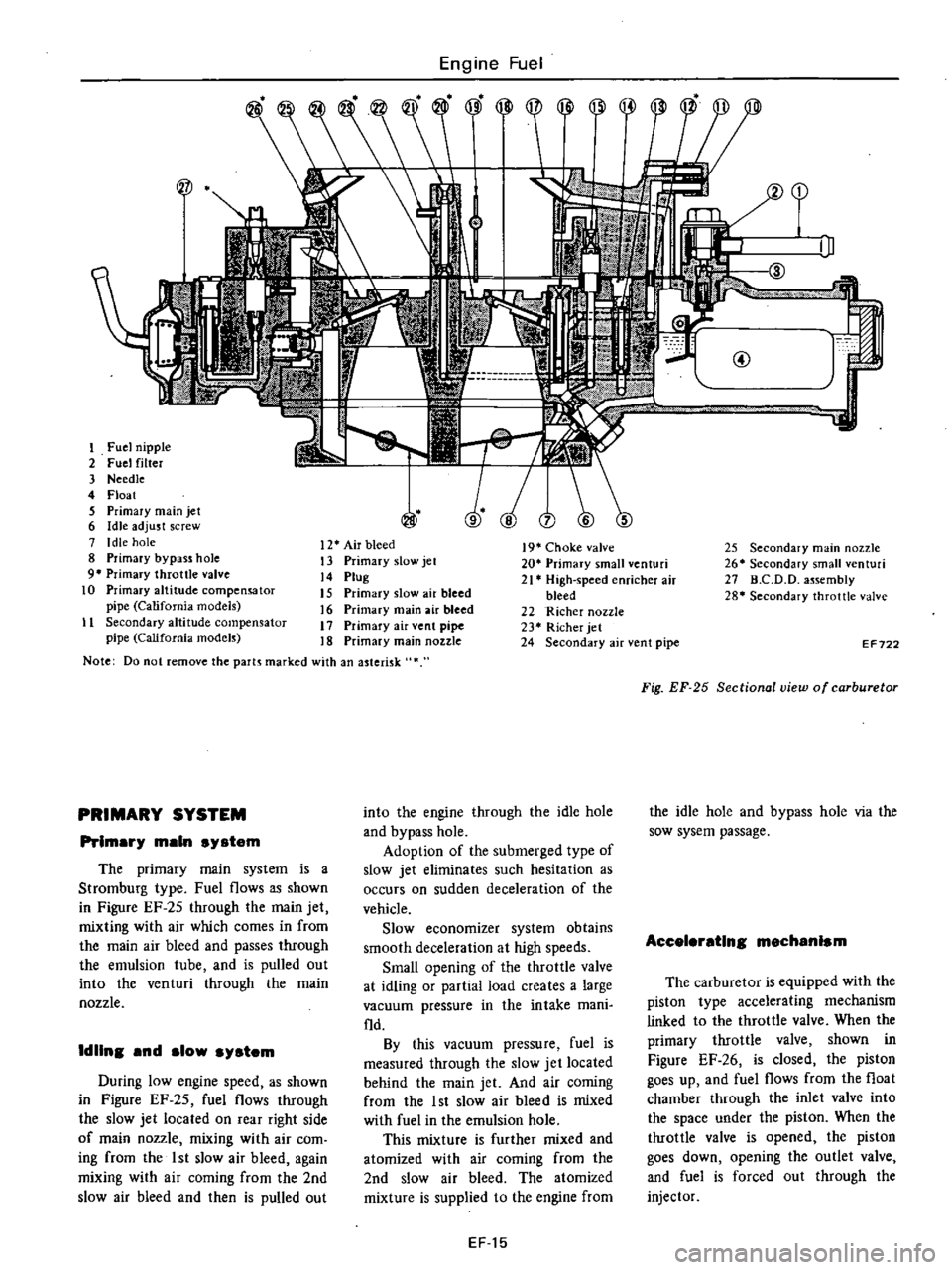
PRIMARY
SYSTEM
Prlmar
main
s
stem
The
primary
main
system
is
a
Stromburg
type
Fuel
flows
as
shown
in
Figure
EF
25
through
the
main
jet
mixting
with
air
which
comes
in
from
the
main
air
bleed
and
passes
through
the
emulsion
tube
and
is
pulled
out
into
the
venturi
through
the
main
nozzle
IdUns
and
slow
s
stem
During
low
engine
speed
as
shown
in
Figure
EF
25
fuel
flows
through
the
slow
jet
located
on
rear
right
side
of
main
nozzle
mixing
with
air
com
ing
from
the
1st
slow
air
bleed
again
mixing
with
air
coming
from
the
2nd
slow
air
bleed
and
then
is
pulled
out
I
III
@
19
Choke
valve
20
Primary
small
venturi
21
High
speed
enricher
air
bleed
22
Richer
nozzle
23
Richer
jet
24
Secondary
air
vent
pipe
into
the
engine
through
the
idle
hole
and
bypass
hole
Adoption
of
the
submerged
type
of
slow
jet
eliminates
such
hesitation
as
occurs
on
sudden
deceleration
of
the
vehicle
Slow
economizer
system
obtains
smooth
deceleration
at
high
speeds
Small
opening
of
the
throttle
valve
at
idling
or
partial
load
creates
a
large
vacuum
pressure
in
the
intake
mani
fld
By
this
vacuum
pressure
fuel
is
measured
through
the
slow
jet
located
behind
the
main
jet
And
air
coming
from
the
1st
slow
air
bleed
is
mixed
with
fuel
in
the
emulsion
hole
This
mixture
is
further
mixed
and
atomized
with
air
coming
from
the
2nd
slow
air
bleed
The
atomized
mixture
is
supplied
to
the
engine
from
EF15
25
Secondary
main
nozzle
26
Secondary
small
enturi
27
D
C
D
D
a
sembly
28
Secondary
throttle
valve
EF722
Fig
EF
25
Sectional
view
of
carburetor
the
idle
hole
and
bypass
hole
via
the
sow
sysem
passage
Accele
atlns
mechanism
The
carburetor
is
equipped
with
the
piston
type
accelerating
mechanism
linked
to
the
throttle
valve
When
the
primary
throttle
valve
shown
in
Figure
EF
26
is
closed
the
piston
goes
up
and
fuel
flows
from
the
float
chamber
through
the
inlet
valve
into
the
space
under
the
piston
When
the
throttle
valve
is
opened
the
piston
goes
down
opening
the
outlet
valve
and
fuel
is
forced
out
through
the
injector
Page 122 of 537
AUtomatic
trailamlsalon
modela
I
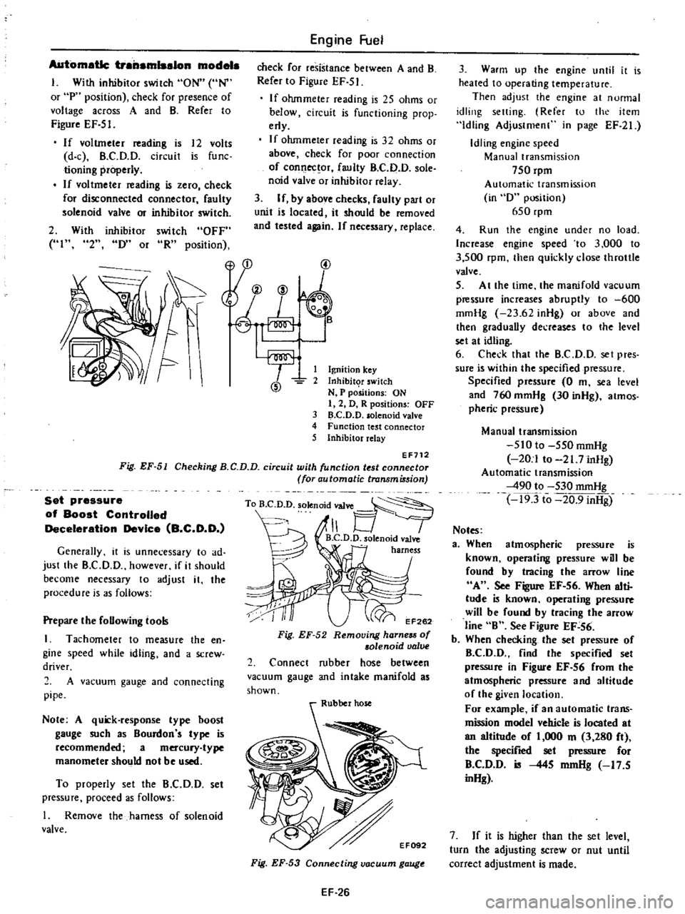
With
inhibitor
switch
ON
UN
or
P
position
check
for
presence
of
voltage
across
A
and
B
Refer
to
Figure
EF
51
If
voltmeter
ading
is
12
volts
d
c
B
C
D
O
circuit
is
func
tioning
properly
If
vol
tmeter
ading
is
zero
check
for
disconnected
connector
faulty
solenoid
valve
m
inhibitor
switch
2
With
inhibitor
switch
OFF
HI
2
IY
or
oR
position
Engine
Fuel
check
for
resistance
between
A
and
B
Refer
to
Figure
EF
51
If
ohmmeter
reading
is
25
ohms
or
below
circuit
is
functioning
prop
erly
If
ohmmeter
reading
is
32
ohms
or
above
check
for
poor
connection
of
connec
or
faulty
B
C
D
D
sole
noid
valve
or
inhibitor
relay
3
If
by
above
checks
faulty
part
or
unit
is
located
it
should
be
moved
and
tested
again
If
necessary
replace
yu
@
@
1
Ignition
key
2
Inhibit
T
switch
N
P
positions
ON
I
2
D
R
positions
OFF
3
D
C
D
D
solenoid
valve
4
Function
test
connector
5
Inhibitor
relay
EF712
Fig
EF
51
Checking
B
C
D
D
circuit
with
unction
t
st
connector
for
automatic
transmi
sion
Set
pressure
of
Boost
Controlled
Deceleration
Device
B
C
D
O
Generally
it
is
unnecessary
to
ad
just
the
B
CD
D
however
if
it
should
become
necessary
to
adjust
it
the
procedure
is
3S
follows
Prepare
the
foUowing
tool
I
Tachometer
to
measure
the
en
gine
speed
while
idling
and
a
screw
driver
2
A
vacuum
gauge
and
connecting
pipe
Note
A
quick
response
type
hoost
gauge
such
as
Bourdon
s
type
is
recommended
a
mercury
type
manometer
should
not
be
used
To
properly
set
the
B
C
D
D
set
pressure
proceed
as
follows
I
Remove
the
harness
of
solenoid
valve
To
B
D
D
solenoid
valve
1
B
C
D
D
olenoid
valve
harness
EF262
Fig
EF
52
Removing
harness
of
solenoid
valve
2
Connect
rubber
hose
between
vacuum
gauge
and
intake
manifold
as
shown
Fig
EF
53
Connecting
vacuum
gauge
EF
26
3
Warm
up
the
engine
until
it
is
heated
to
operating
temperature
Then
adjust
the
engine
at
nunnal
idling
setting
Refer
to
the
item
Idling
Adjustmenl
in
page
EF
21
Idling
engine
speed
Manual
transmission
750
rpm
Automatic
transmission
in
D
position
650
rpm
4
Run
the
engine
under
no
load
Increase
engine
speed
to
3
000
to
3
500
rpm
then
quickly
close
throttle
valve
5
At
the
time
the
manifold
vacuum
p
ssure
increases
abruptly
to
600
mmHg
23
62
inHg
or
above
and
then
graduaUy
decreases
to
the
level
set
at
idling
6
Check
that
the
B
C
D
D
set
pres
sure
is
within
the
specified
pressure
Specified
pressure
0
m
sea
level
and
760
mmHg
30
inHg
atmos
pheric
pressu
Manual
transmission
510
to
550
mmHg
20
1
to
21
7
inHg
Automatic
transmission
490
to
530
mmHg
19Tto
20
9
inHg
Notes
a
When
atmospheric
pressure
is
known
operating
pressure
will
be
found
by
tracing
the
arrow
line
A
See
Figure
EF
56
When
alti
tude
is
known
operating
pressure
will
be
found
by
tracing
the
arrow
line
B
See
Figu
EF
56
b
When
checking
the
set
pressu
of
B
CD
D
find
the
specified
set
pressu
in
Figure
EF
56
from
the
atmospheric
pressure
and
altitude
of
the
given
location
For
example
if
an
automatic
trans
mission
model
vehicle
is
located
at
an
altitude
of
1
000
m
3
280
ft
the
specified
set
p
ssu
for
B
C
D
D
is
445
mmHg
17
5
inHg
7
If
it
is
higher
than
the
set
level
turn
the
adjusting
screw
or
nut
until
correct
adjustment
is
made
Page 123 of 537
Non
California
models
Adjusting
screw
Counterclockwise
California
models
Adjusting
nut
Clockwise
Non
California
models
1
2
1
Adjusting
screw
s
2
Cover
e
California
models
t
1
Adjusting
nut
2
Lock
spring
EC692
Fig
EF
54
Adjusting
et
pressure
vacuum
gauge
Intake
gjl
11
Road
test
CD
ET037
Engine
Fuel
Note
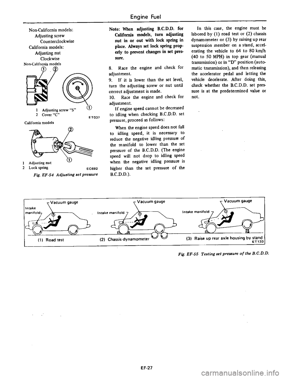
When
adjusting
B
C
D
D
for
California
models
turn
adjusting
nut
in
or
out
with
lock
spring
in
place
Always
set
lock
spring
prop
erly
to
prevent
changes
in
set
pres
sure
8
Race
the
engine
and
check
for
adjustment
9
If
it
is
lower
than
the
set
level
turn
the
adjusting
screw
or
nut
until
correct
adjustment
is
made
10
Race
the
engine
and
check
for
adjustment
If
engine
speed
cannot
be
decreased
to
idling
when
checking
B
C
D
D
set
pressure
proceed
as
follows
When
the
engine
speed
does
not
fall
to
idling
speed
it
is
necessary
to
reduce
the
negative
idling
pressure
of
the
manifold
to
lower
than
the
set
pressure
of
the
B
C
D
O
The
engine
speed
will
not
drop
to
idling
speed
when
the
negative
idling
pressure
is
higher
Ihan
the
sel
pressure
of
the
B
C
O
O
acuum
gauge
Intakema
M
V
9iI
21
Chas
amomeler
In
this
case
the
engine
must
be
labored
by
I
road
test
or
2
chassis
dynamometer
or
3
by
raising
up
rear
suspension
member
on
a
stand
accel
erating
the
vehicle
to
64
to
80
km
h
40
10
50
MPH
in
top
gear
manual
transmission
or
in
0
position
auto
matic
transmission
and
then
releasing
the
accelerator
pedal
and
letting
the
vehicle
decelerate
After
doing
this
check
whether
the
B
C
O
D
set
pres
sure
is
at
the
predetermined
value
or
not
Vacuum
gauge
n
i
Y
3
Raise
up
rear
axle
housing
by
stand
ET133
Fig
EF
55
Testing
sel
pre
ure
of
the
B
C
D
D
EF
27
Page 131 of 537
Engine
Fuel
SERVICE
DATA
AND
SPECIFICATIONS
Airclelllcr
Ail
control
val
partially
opem
Air
ntrol
valve
fuUy
opens
Idle
ompensatoI
partially
opens
Hi
mettiNo
l
Bi
metal
No
2
Idle
ompen
tor
fully
opens
Bi
metal
No
1
Hi
metd
No
2
Fuels
Stem
Fuel
prtuure
Fuel
pump
apacHy
C
rbu
tor
C
rbu
tor
type
Carburetor
model
Oc
oF
oCe
F
oCe
F
Oc
OF
kpJcm2
poi
US
pt
min
at
rpm
Outlet
diameter
Venturi
diameter
Main
jet
Main
air
bleed
Slow
jet
Power
val
Float
level
U
fuel
preuure
rom
in
mm
in
mm
in
kg
cm2
psi
Adjustment
Engine
idling
Ignition
timing
Idle
speed
CO
at
mloro
Fuel
level
adjustment
Gap
between
Ive
stem
and
noat
at
mm
in
H
H
h
Fast
idle
adjwtmcnt
Fast
idle
earn
tint
step
Gap
between
throttle
IYe
and
carburetor
body
mm
in
Vacuum
break
adjustment
Gap
between
choke
alve
and
carburetor
body
mm
in
Choke
unloadel
adjusttncnt
Gap
between
choke
alw
and
carburetor
body
rom
in
Bi
metalsettinl
Bi
metal
resistance
at
2Ioe
700F
n
Bi
metalsettina
lnterloc
k
opcnina
of
primary
and
secondary
throtUc
valves
mmOn
Duh
pot
adjustment
without
loadin
I
m
Anti
diclClinasolenoid
valV
C
tiahtenina
torque
ka
m
in
lb
a
c
D
D
set
p
JSure
0
m
sea
level
and
760
mmHg
30
inlla
atmospheric
pressure
J
mmHa
inHg
R
C
D
D
tiahteninl
torque
kg
m
n
b
Nl
n
California
modell
Manual
transmiSsion
I
Automatic
transmission
California
modeb
Manual
transmission
I
Automatic
transmission
30
to
54
86
to
129
above
55
131
30
to
54
86
to
129
above
55
131
60
to
70
140
to
158
70
to
90
158
to
194
60
to
70
140
to
158
70
to
90
158
to
194
above
70
158
above
90
194
above
70
158
above
90
194
0
21
to
0
27
2
99
to
3
84
t
OOO
2
i
I
OOO
0
21
to
0
27
2
99
to
3
84
1
000
2
i
I
OOO
Strombcra
type
OCH340
7A
DCH340
48A
Stromt
rg
type
DCH34Q
45B
DCH340
46A
Primary
Secondary
Primary
Secondary
Primary
Secondary
Primary
Secondary
30
I8t
340
339
30
1
181
34
1
339
30
1
181
34
1
339
30
1
181
34
1
339
24
0
945
310
220
24
0
945
31
1
220
24
0
945
31
1
220
24
0
945
31
1
220
199
1160
199
1160
1101
1160
101
1160
170
160
170
160
170
60
170
1
60
148
1100
148
1100
148
1100
148
180
143
143
140
140
23
0
906
23
0
906
23
0
906
23
0
906
0
17
2
408
0
17
2
40B
0
17
2
408
0
17
2
408
1201750
rpm
CO
2
1
120
650
rpm
0
100
750rpm
C02
t
1
120
650
rpm
0
position
CO
2
t
1
position
CO
2
t
1
7
2
0
283
7
2
0
283
7
2
0
283
7
2
0
283
23
0
906
23
0
906
23
0
906
23
0
906
1
3
to
1
7
1
3
to
1
7
1
3
to
1
7
1
3
to
1
7
0
051
to
0
067
0
051
to
0
067
0
051
to
0
067
0
051
to
0
067
1
33
to
1
47
1
58
to
1
72
1
33
to
1
47
1
58
to
1
72
0
0524
to
0
0579
0
0622
to
0
0677
0
0524
to
0
0579
0
0622
to
0
0677
1
42
0
056
1
42
0
056
1
42
0
056
1
5
0
059
2
45
0
096
2
45
0
096
2
4
0
096
2
45
0
096
3
7
to
8
9
3
7
to
8
9
3
7
to
B
9
3
7
to
8
9
Center
of
the
ndex
mark
Center
of
the
index
mark
7
38
0
291
7
38
0
291
7
38
0
290
7
38
0
291
1
900
to
2
100
1
650
to
1
850
1
900
to
2
100
1
650
to
1
850
180
to
350
156
to
304
180
to
350
156
to
304
180
to
350
156
to
304
180
to
350
156
to
304
510
to
550
490
to
530
510
to
550
490
to
530
20
1
to
21
7
19
3
to
20
9
20
1
to
21
7
19
3
to
20
9
20
to
40
17
4
to
34
1
20
to
40
11
4
to
34
7
20
to
40
17
4
to
34
7
20
to
40
17
4
to
34
1
EF
35
Page 132 of 537
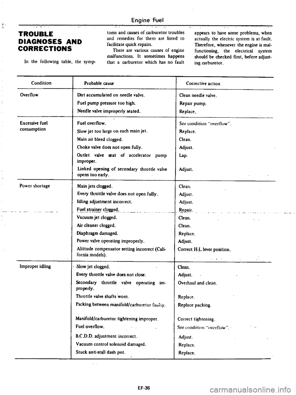
Engine
Fuel
toms
and
causes
of
carburetor
troubles
and
remedies
for
them
are
listed
to
facilitate
quick
repairs
There
are
various
causes
of
engine
malfunctions
It
sometimes
happens
that
a
carburetor
which
has
no
fault
TROUBLE
DIAGNOSES
AND
CORRECTIONS
In
the
following
table
the
syml
Condition
Probable
cause
Overflow
Dirt
accumulated
on
needle
valve
Fuel
pump
pressure
too
high
Needle
valve
improperly
seated
Excessive
fuel
consumption
Fuel
overflow
Slow
jet
too
large
on
each
main
jet
Main
air
bleed
clogged
Choke
valve
does
not
open
fully
Outlet
valve
seat
of
accelerator
pump
improper
Linked
opening
of
secondary
throttle
valve
opens
too
early
Power
shortage
Main
jets
clogged
Every
throttle
valve
does
not
open
fully
Idling
adjustment
incorrect
FIICI
tr
clogged
Vacuum
jet
clogged
Air
c1eane
clogged
Diaphragm
damaged
Power
valve
operating
improperly
Altitude
compensator
setting
incorrect
Cali
fornia
models
Improper
idling
Slow
jet
clogged
Every
throttle
valve
does
not
close
Secondary
throttle
valve
operating
im
properly
Throttle
valve
shafts
worn
Packing
between
manifold
carburetor
fauJiy
Manifold
carburetor
tightening
improper
Fuel
overflow
B
C
D
D
adjustment
incorrect
Vacuum
control
solenoid
damaged
Stuck
anti
stall
dash
pot
EF
36
appears
to
have
some
problems
when
actually
the
electric
system
is
at
fault
Therefore
whenever
the
engine
is
mal
functioning
the
electrical
system
should
be
checked
rust
before
adjust
ing
carburetor
Corrective
action
Clean
needle
valve
Repair
pump
Re
place
See
condition
overflow
Replace
Clean
Adjust
Lap
Adjust
Clean
Adjust
AdjusL
pa
ir
Clean
Clean
Replace
Adjust
Correct
H
L
lever
position
Clean
Adjust
Overhaul
and
clean
Replace
Replace
packing
Correct
tightening
See
l
ondition
ov
rl1ow
Adjust
Replace
Replace
Page 164 of 537
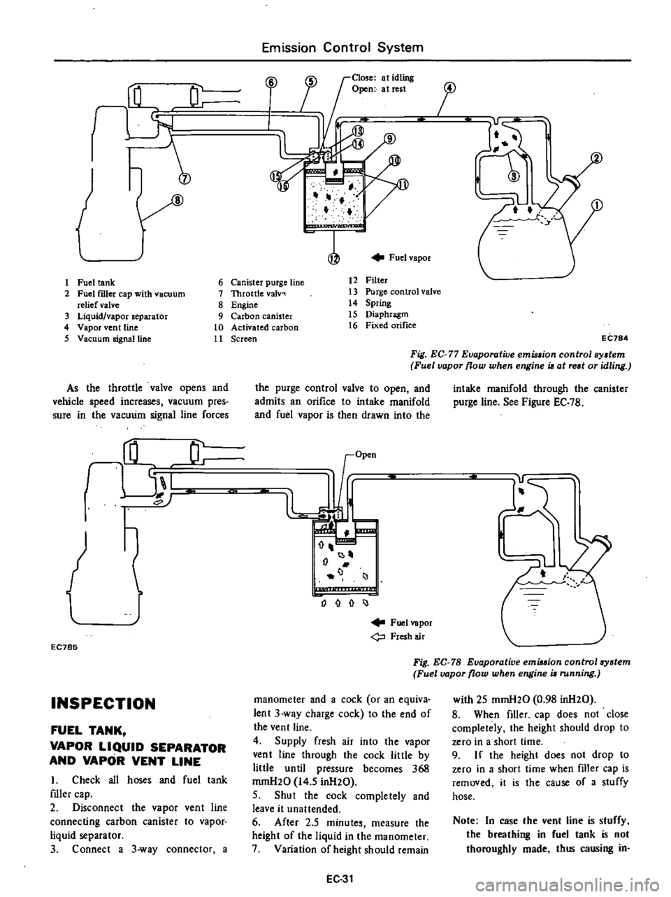
J
1
Fuel
tank
2
Fuel
f1l1er
cap
with
vacuum
relief
valve
3
Liquid
vapor
separator
4
Vapor
vent
line
5
Vacuum
signalUne
As
the
throttle
valve
opens
and
vehicle
speed
increases
vacuum
pres
sure
in
the
vacuum
signal
line
forces
rHL
JL
I
EC785
INSPECTION
FUEL
TANK
VAPOR
LIQUID
SEPARATOR
AND
VAPOR
VENT
LINE
I
Check
all
hoses
and
fuel
tank
mler
cap
2
Disconnect
the
vapor
vent
line
connecting
carbon
canister
to
vapor
liquid
separator
3
Connect
a
3
way
connector
a
Emission
Control
System
Close
at
idling
Open
at
rest
i
J
17
f
Fuel
vapor
6
Canister
purge
line
7
Throttle
valv
8
Engine
9
Carbon
canister
10
Activated
carbon
11
Screen
12
Filter
13
Purge
control
valve
14
Spring
15
Diaphragm
16
Fixed
orifice
i
j
EC784
Fig
EC
77
Evaporative
emu
ion
control
sy
tem
Fuel
vapor
flow
when
engine
i6
at
red
or
idling
the
purge
control
valve
to
open
and
admits
an
orifice
to
intake
manifold
and
fuel
vapor
is
then
drawn
into
the
I
J
o
I
Fuel
vapor
Fresh
air
intake
manifold
through
the
canister
purge
line
See
Figure
EC
7B
Fig
EC
78
Evaporative
emiuion
control
system
Fuel
vapor
flow
when
engine
i
running
manometer
and
a
cock
or
an
equiva
lent
3
way
charge
cock
to
the
end
of
the
vent
line
4
Supply
fresh
air
into
the
vapor
vent
line
through
the
cock
little
by
little
until
pressure
becomes
368
mrnH20
14
5
inH20
5
Shut
the
cock
completely
and
leave
it
unattended
6
After
2
5
minutes
measure
the
height
of
the
liquid
in
the
manometer
7
Variation
of
height
should
remain
EC
31
with
25
mmH20
0
98
inH20
8
When
filler
cap
does
not
close
completely
the
height
should
drop
to
zero
in
a
short
time
9
I
f
the
height
does
not
drop
to
zero
in
a
short
time
when
filler
cap
is
removed
it
is
the
cause
of
a
stuffy
hose
Note
In
case
the
vent
line
is
stuffy
the
breathing
in
fuel
tank
is
not
thoroughly
made
thus
causing
in
Page 219 of 537
Engine
Removal
Installation
ENGINE
REMOVAL
AND
INSTAllATION
REMOVAL
INSTALLATION
ENGINE
MOUNTING
INSULATORS
REMOVAL
It
is
much
easier
to
remove
engine
and
transmission
as
a
single
unit
than
to
remove
them
separately
After
re
moval
engine
can
be
separated
from
transntission
assembly
Notes
a
Be
sure
to
hoist
engine
and
jack
up
transmission
in
a
safe
manner
b
Use
fender
cove
to
protect
vehicle
body
1
Remove
battery
2
Scribe
hood
hinge
location
for
proper
reinstallation
and
remove
hood
Note
Have
an
assistant
help
you
so
as
to
prevent
damage
to
body
3
Drain
radiator
coolant
4
Disconnect
upper
and
lower
radiator
hoses
from
engine
5
Remove
two
oil
cooler
hoses
from
lower
end
of
radiator
Auto
ma
tic
transmission
models
only
6
Remove
radiator
shroud
7
Remove
four
bolts
securing
radia
tor
and
detach
radiator
Note
Always
tighten
securing
bolt
at
upper
right
hand
side
together
with
body
harness
terminal
8
Remove
carburetor
air
cleaner
as
follows
Remove
fresh
air
duct
Remove
hot
air
duct
Loosen
air
cleaner
band
bolt
and
air
cleaner
supporting
bolts
Disconnect
air
cleaner
ta
air
pump
hose
Disconnect
air
cleaner
to
rocker
cover
hose
at
rocker
cover
Disconnect
air
cleaner
to
air
control
valve
hose
California
models
only
CONTENTS
ER
2
ER
3
ER
3
FRONT
INSULATOR
REAR
INSULATOR
TIGHTENING
TORQUE
ER
4
ER
4
ER
4
Disconnect
air
deaner
to
A
B
valve
hose
Disconnect
air
cleaner
ta
vacuum
hoses
Note
Protect
carburetor
from
dust
and
foreign
matter
by
placing
cover
over
air
inlet
opening
9
Disconnect
fuel
pump
to
fuel
fdter
hose
and
return
hose
10
Disconnect
carbon
canister
hose
on
engine
side
II
Disconnect
air
pump
air
C1eaner
to
al
p
p
hose
12
Disconnect
following
cables
wires
and
hoses
Engine
ground
cable
Accelerator
wire
at
carburetor
High
tension
cable
between
ignition
coil
and
distributor
Wire
to
distributor
at
body
ter
minal
Wire
to
oil
pressure
switch
Wires
to
thermal
transmitter
Wires
to
B
C
p
D
cut
solenoid
Non
California
models
only
auto
choke
heater
and
anti
dieseling
solenoid
Wires
to
alternator
Wires
to
starter
motor
Heater
inlet
and
outlet
hoses
if
so
equipped
Vacuum
hose
of
Master
Vac
at
in
taJce
manifold
Wires
for
back
up
lamp
switch
Cable
to
speedometer
13
Remove
transmission
control
linkage
from
transmission
Manual
transmission
models
I
Detach
rubber
boot
2
Remove
E
ring
and
control
lever
pin
from
transmission
striking
rod
guide
and
remove
control
lever
ER
2
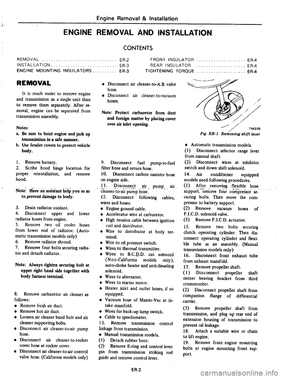
Fig
ER
l
Automatic
transmission
models
I
Disconnect
selector
range
lever
from
manual
shaft
2
Disconnect
wires
at
inhibitor
switch
and
down
shift
solenoid
14
Air
conditioner
equipped
models
need
following
procedures
1
After
removing
flexible
hose
support
remove
four
comi
ressor
se
curing
bolts
Then
move
the
com
pressor
to
battery
support
2
Remove
vacuum
hoses
of
F
LC
D
solenoid
valve
3
Remove
F
LC
D
actuator
15
Remove
two
bolts
securing
clutch
operating
cylinder
Then
dis
connect
operating
cylinder
and
flexi
ble
tube
as
an
assembly
Manual
transmission
models
only
16
Disconnect
front
exhaust
tube
from
exhaust
manifold
17
Remove
propeller
shaft
I
Disconnect
propeller
shaft
center
bearing
bracket
from
third
crossmember
2
Disconnect
propeller
shaft
from
companion
flange
of
differential
carrier
3
Remove
propeller
shaft
from
transmission
and
plug
up
rear
end
of
extension
housing
of
transmission
to
prevent
oil
leakage
18
Attach
a
suitable
wire
or
chain
to
lift
engine
19
Remove
front
engine
mounting
bolts
at
engine
mounting
front
sup
port
Page 459 of 537

Body
Electrical
System
METERS
AND
GAUGES
COMBINATION
METER
COMBINATION
METER
CIRCUIT
DIAGRAM
REMOVAL
AND
INSTALLATION
SPEEDOMETER
REMOVAL
AND
INSTALLATION
ODOMETER
SWITCH
REMOVAL
AND
INSTALLATION
FUEL
GAUGE
AND
WATER
TEMPERATURE
GAUGE
DESCRIPTION
REMOVAL
AND
INSTALLATION
OIL
PRESSURE
WARNING
LAMP
DESCRIPTION
01
L
PRESSURE
SWITCH
COMBINATION
METER
COMBINATION
METER
CIRCUIT
DIAGRAM
@
BE6828
CONTENTS
BE
14
BE
14
BE
16
BE
16
BE
16
BE
16
8E
16
BE
16
BE
16
BE
16
8E
17
BE
17
BE
17
Turn
signal
indicator
lamp
L
H
OIL
0
BEAM
BE
14
Meter
illumination
lamps
M
T
only
9
9
Turn
sq
nal
indicator
lamp
lL
J
R
H
Tj
O
iJ
I
l
g
r
i
o
I
l8
J
CHARGE
WARNING
LAMP
DESCRIPTION
HAND
BRAKE
WARNING
LAMP
DESCRIPTION
HAND
BRAKE
SWITCH
METER
ILLUMINATION
INDICATOR
AND
WARNING
BULBS
REMOVAL
AND
INSTALLATION
8ULB
SPECIFICATIONS
TROUBLE
DIAGNOSES
AND
CORRECTIONS
SPEEDOMETER
WATER
TEMPERATURE
AND
FUEL
GAUGES
OIL
PRESSURE
AND
CHARGE
WARNING
LAMPS
Voltage
regulator
TEMP
FUEL
CHG
0
BRK
C
I
Speedometer
2
Thermometer
3
Fuel
meter
4
Tachometer
Option
5
Cluster
lid
6
Speedometer
cable
7
Speed
switch
amplifier
Manual
transmission
only
BE
17
BE
17
BE
18
BE
18
8E
18
8E
18
BE
18
BE
18
BE
18
BE
18
BE
19
BE
20
Q
Speed
switch
BE856A
Fig
BE
21
Ci1
Cuit
diagram
of
combination
meter