oil level DATSUN PICK-UP 1977 User Guide
[x] Cancel search | Manufacturer: DATSUN, Model Year: 1977, Model line: PICK-UP, Model: DATSUN PICK-UP 1977Pages: 537, PDF Size: 35.48 MB
Page 96 of 537
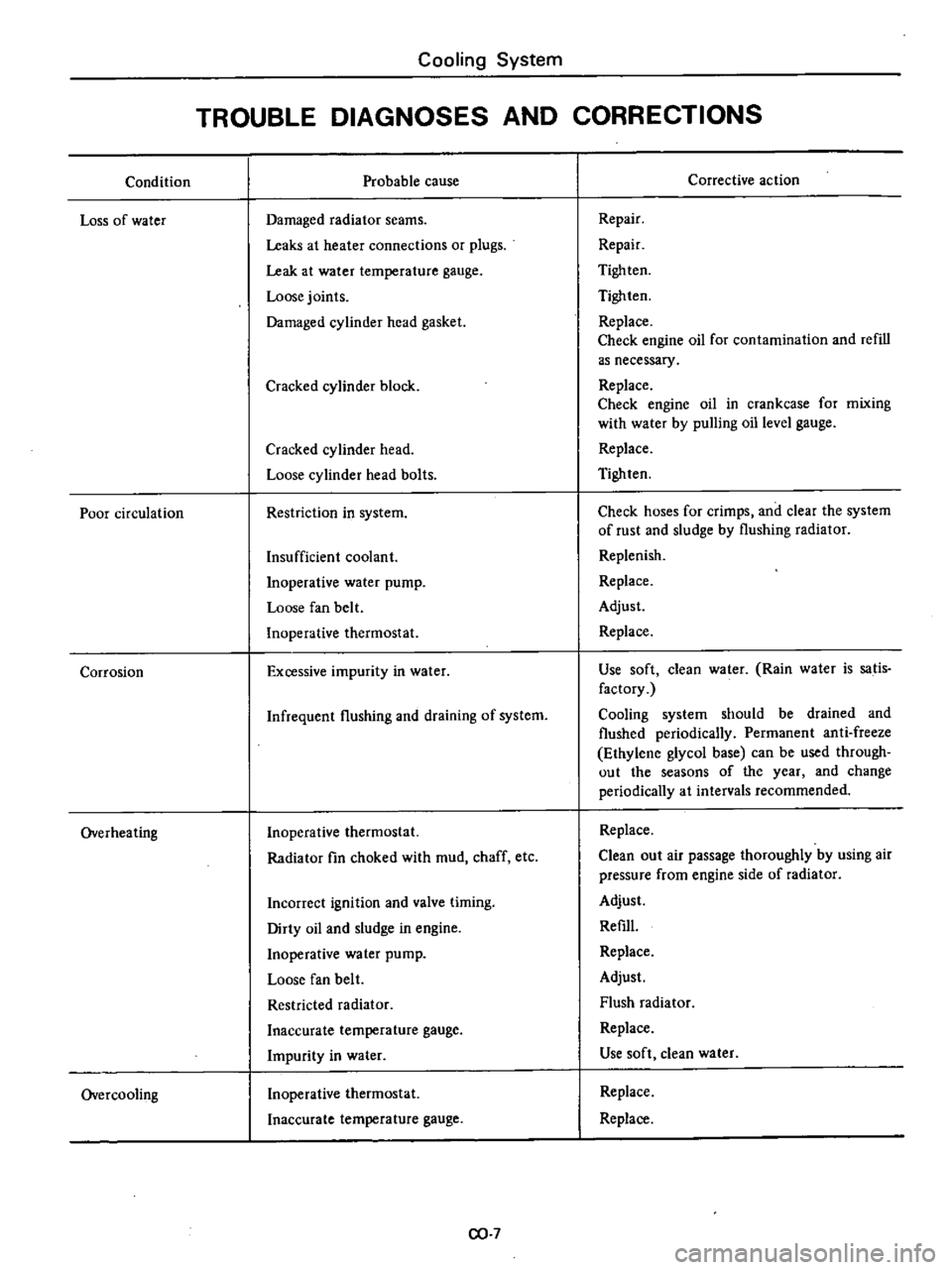
Condition
Loss
of
water
Poor
circulation
Corrosion
Overheating
Overcooling
Cooling
System
TROUBLE
DIAGNOSES
AND
CORRECTIONS
Probable
cause
Damaged
radiator
seams
Leaks
at
heater
connections
or
plugs
Leak
at
water
temperature
gauge
Loose
joints
Damaged
cylinder
head
gasket
Cracked
cylinder
block
Cracked
cylinder
head
Loose
cylinder
head
bolts
Restriction
in
system
Insufficient
coolant
Inoperative
water
pump
Loose
fan
belt
Inoperative
thermostat
Excessive
impurity
in
water
Infrequent
flushing
and
draining
of
system
Inoperative
thermostat
Radiator
fin
choked
with
mud
chaff
etc
Incorrect
ignition
and
valve
timing
Dirty
oil
and
sludge
in
engine
Inoperative
water
pump
Loose
fan
belt
Restricted
radiator
Inaccurate
temperature
gauge
Impurity
in
water
Inoperative
thermostat
Inaccurate
temperature
gauge
CO
7
Corrective
action
Repair
Repair
Tigh
ten
Tighten
Replace
Check
engine
oil
for
contamination
and
refill
as
necessary
Replace
Check
engine
oil
in
crankcase
for
mixing
with
water
by
pulling
oil
level
gauge
Replace
Tighten
Check
hoses
for
crimps
and
clear
the
system
of
rust
and
sludge
by
flushing
radiator
Replenish
Replace
Adjust
Replace
Use
soft
clean
water
Rain
water
is
satis
factory
Cooling
system
should
be
drained
and
flushed
periodically
Permanent
anti
freeze
Ethylene
glycol
base
can
be
used
through
out
the
seasons
of
the
year
and
change
periodically
at
intervals
recommended
Replace
Clean
out
air
passage
thoroughly
by
using
air
pressure
from
engine
side
of
radiator
Adjust
Refill
Replace
Adjust
Flush
radiator
Replace
Use
soft
clean
water
Replace
Replace
Page 107 of 537
3
Check
diaphragm
for
small
holes
carcks
or
wear
4
Check
rocker
arm
for
wear
at
the
mating
portion
with
camshaft
5
Check
rocker
arm
pin
for
wear
A
worn
pin
may
cause
oil
leakage
6
Check
all
other
components
for
any
abnormalities
and
replace
if
neces
sary
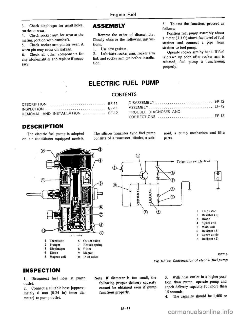
DESCRIPTION
INSPECTION
REMOVAL
AND
INSTALLATION
DESCRIPTION
The
electric
fuel
pump
is
adopted
on
air
conditioner
equipped
models
Engine
Fuel
ASSEMBLY
Reverse
the
order
of
disassembly
Closely
observe
the
following
instruc
tions
L
Use
new
gaskets
2
Lubricate
rocker
ann
rocker
arm
link
and
rocker
arm
pin
before
installa
tion
3
To
test
the
function
proceed
as
follows
Position
fuel
pump
assembly
about
I
meter
3
3
ft
above
fuel
level
of
fuel
strainer
and
connect
a
pipe
from
strainer
to
fuel
pump
Operate
rocker
arm
by
hand
If
fuel
is
drawn
up
soon
after
rocker
arm
is
released
fuel
pump
is
functioning
properly
ELECTRIC
FUEL
PUMP
CONTENTS
EF
11
EF
11
EF
12
DISASSEMBL
Y
ASSEMBL
Y
TROUBLE
DIAGNOSES
AND
CORRECTIONS
EF
12
EF
12
The
silicon
transistor
type
fuel
pump
consists
of
a
transistor
diodes
a
sole
I
Tr
lOsistor
6
Ou
tIet
valve
2
Plunger
7
Return
spring
3
Diaphragm
8
Filter
4
Diode
9
Magnet
5
Magnet
coil
10
Inlet
valve
INSPECTION
I
Disconnect
fuel
hose
at
pump
outlet
2
Connect
a
suitable
hose
approxi
mately
6
mm
0
24
in
inner
dia
meter
to
pump
outlet
ev
J
J
Note
If
diameter
is
too
small
the
following
proper
delivery
capacity
cannot
be
obtained
even
if
pump
functions
properly
EF
11
EF
13
noid
a
pump
mechanism
and
filter
parts
I
T
nsistor
2
Re
ist
f
I
3
Dinde
4
Signal
coil
5
Main
coil
6
Resistor
3
7
Zener
dlOdl
8
Resistor
2
EF719
Fig
EF
22
Construction
of
electric
fuel
pump
3
With
hose
outlet
in
a
higher
posi
tion
than
pump
operate
pump
and
check
delivery
capacity
for
more
than
15
seconds
4
The
capacity
should
be
I
400
cc
Page 135 of 537

There
are
three
types
of
control
system
These
are
J
Closed
type
CIllnkcase
emission
control
system
Emission
Control
System
of
GENERAL
DESCRIPTION
2
Exhaust
emission
control
system
3
Evaporative
ell
lhsion
control
sys
tem
Pericxiic
inspection
and
required
seCV1Clng
of
these
systems
should
be
carried
out
to
reduce
harmful
emis
sions
to
a
minimum
CRANKCASE
EMISSION
CONTROL
SYSTEM
c
01
Lkf
If
1
TIL
II
tll
1
j
GUuuu
DESCRIPTION
This
system
returns
blow
by
gas
to
both
the
intake
manifold
and
carbure
tor
air
cleaner
The
positive
crankcase
ventilation
p
C
V
valve
is
provided
to
conduct
crankcase
blow
by
gas
to
the
intake
manifold
During
partial
throttle
operation
of
the
engine
the
intake
manifold
sucks
the
blow
by
gas
through
the
P
C
V
valve
Normally
the
capacity
of
the
valve
is
sufficient
to
handle
any
blow
by
and
a
small
amount
of
ventilating
air
4
c
Fresh
air
Blow
by
gas
The
ventilating
air
is
then
drawn
from
the
dust
side
of
the
cadlUretor
air
cleaner
tluough
the
tube
con
necting
carburetor
air
cleaner
to
rock
er
cover
into
the
crankcase
Under
full
tluottle
condition
the
manifold
vacuwn
is
insufficient
to
draw
the
blow
by
flow
tluough
the
valve
and
its
flow
goes
through
the
tube
connection
in
the
reverse
diree
tion
On
vehicles
with
an
excessively
high
blow
by
some
of
the
flow
will
go
through
the
tube
connection
to
carbu
retor
air
cleaner
under
all
conditions
1
Sealtypc
oil
level
gauge
2
Bame
plate
3
Flame
arrester
4
Filler
5
P
C
Y
valve
6
Steel
net
7
Bame
plate
EC716
Fig
EC
l
Crankcase
miaion
control
ay
tem
EC
2
INSPECTION
P
c
V
VALVE
AND
FILTER
Checking
P
C
V
valve
in
accord
ance
with
the
following
method
With
engine
running
at
idle
remove
the
ventilator
hose
from
P
C
V
valve
if
the
valve
is
working
a
hissing
noise
will
be
heard
as
air
passes
through
the
valve
and
a
strong
vacuwn
should
be
felt
immediately
when
a
fmger
is
placed
over
valve
inlet
Replace
P
C
V
valve
and
filter
in
accordance
with
the
maintenance
schedule
VENTILATION
HOSE
1
Check
hoses
and
hose
connec
tions
for
leaks
2
Disconnect
all
hoses
and
clean
with
compressed
air
If
any
hose
cannot
be
free
of
obstructions
replace
Ensure
that
flame
arrester
is
surely
inserted
in
hose
between
air
cleaner
and
rocker
cover
Page 229 of 537
Inspection
Note
To
clean
or
wash
all
parts
of
master
cylinder
operating
cylinder
and
piping
clean
brake
fluid
must
be
used
Never
use
minera10ils
llUch
as
gasoline
and
kerosene
It
will
ruin
the
rubber
parts
of
the
hydrau
lic
system
I
Check
cylinder
and
piston
for
uneven
wear
or
damage
and
if
neces
sary
replace
2
If
the
clearance
between
cylinder
and
piston
is
more
than
0
15
mm
0
0059
in
replace
cylinder
3
Renew
piston
cup
when
dis
assembled
It
must
also
be
replaced
when
wear
or
deformation
due
to
fatigue
or
damage
is
found
4
Damaged
dust
cover
oil
reservoir
or
cap
should
be
replaced
Return
spring
and
valve
spring
must
also
be
replaced
when
they
are
broken
or
weak
5
Replace
clutch
hose
and
tube
if
any
abnormal
sign
of
damage
or
de
fro
ti
n
is
found
OPERATING
CYLINDER
Removal
and
installation
Removal
1
Detach
clutch
hose
from
operat
ing
cylinder
2
Remove
two
bolts
securing
op
erating
cylinder
to
clutch
housing
Installation
Install
in
the
reverse
order
of
re
moval
Observe
the
following
instructions
Bleed
air
thoroughly
from
clutch
hydraulic
system
2
Do
not
install
return
spring
or
clutch
will
not
be
disengaged
properly
Tightening
torque
Operating
cylinder
securing
bolt
2
5
to
3
5
kg
m
18
to
25
ft
lb
Bleeder
screw
0
7
to
0
9
kg
m
5
1
to
6
5
ft
Ib
Clutch
hose
connector
1
7
to
2
0
kg
m
12
to
14
ft
b
CLUTCH
Disassembly
and
assembly
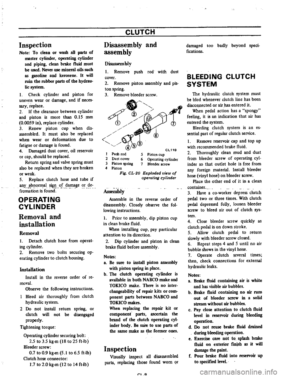
Disassembly
1
Remove
push
rod
with
dust
cover
2
Remove
piston
assembly
and
pis
ton
spring
3
Remove
bleeder
screw
1
6
Cl11B
5
Piston
cup
6
Operating
cylinder
7
Bleeder
screw
1
Push
rod
2
Dust
cover
3
Piston
spring
4
Piston
Fig
CL
20
Exploded
view
of
operating
cyUnder
Assembly
Assemble
in
the
reverse
order
of
disassembly
Closely
observe
the
fol
lowing
instructions
1
Prior
to
assembly
dip
piston
cup
in
clean
brake
fluid
When
installing
cup
pay
particular
attention
to
its
direction
2
Dip
cylinder
and
piston
in
clean
brake
fluid
before
assembly
Notes
a
Be
sure
to
install
piston
assembly
with
piston
spring
in
place
b
The
clutch
operating
cylinder
is
available
in
both
NABCO
make
and
TOKICO
make
There
is
no
inter
changeability
of
repair
kits
or
com
ponent
parts
between
NABCO
and
TOKICO
makes
When
replacing
the
repair
kit
or
component
parts
ascertain
the
brand
of
the
clutch
operating
cyl
inder
bndy
Be
sure
to
use
parts
of
the
same
make
as
the
former
ones
Inspection
Visually
inspect
all
disassembled
parts
replacing
those
found
worn
or
rl
Q
damaged
too
badly
beyond
speci
fications
BLEEDING
CLUTCH
SYSTEM
The
hydraulic
clutch
system
must
be
bled
whenever
clutch
line
has
been
disconnected
or
air
has
entered
it
When
pedal
action
has
a
spongy
feeling
it
is
an
indication
that
air
has
entered
the
system
Bleeding
clutch
system
is
an
es
sential
part
of
regular
clutch
service
I
Remove
reservoir
cap
and
top
up
with
recommended
brake
fluid
2
Thoroughly
clean
mud
and
dust
from
bleeder
screw
of
operating
cyl
inder
so
that
outlet
hole
is
free
from
any
foreign
rnaterial
Install
bleeder
hose
vinyl
hose
on
bleeder
screw
Place
the
other
end
of
it
in
a
clean
container
3
Have
a
co
worker
depress
clutch
pedal
two
or
three
times
With
clu
tch
pedal
depressed
fully
loosen
bleeder
screw
to
bleed
air
out
of
clutch
sys
tern
4
Close
bleeder
screw
quickly
as
clutch
pedal
is
on
down
stroke
5
Allow
clutch
pedal
to
return
slowly
with
bleeder
screw
closed
6
Repeat
steps
4
and
5
until
no
air
bubble
shows
in
the
vinyl
hose
7
Operate
clutch
several
times
then
check
connections
for
external
hydraulic
leaks
Notes
a
Brake
fluid
containing
air
is
white
and
has
visible
air
bubbles
b
Brake
fluid
containing
no
air
runs
out
of
bleeder
screw
in
a
solid
stream
without
air
bubble
c
Pay
close
attention
to
clutch
fluid
level
in
reservoir
during
bleeding
operation
d
Do
not
reuse
brake
fluid
drained
during
bleeding
operation
e
Exercise
care
not
to
splash
brake
fluid
on
exterior
fInish
as
it
will
damage
the
paint
f
Pour
brake
fluid
into
reservoir
up
to
specifIed
level
Page 248 of 537
5
Apply
a
light
coat
of
multi
purpose
grease
to
withdrawal
lever
release
bearing
and
bearing
sleeve
in
stall
them
on
clutch
housing
After
connecting
them
with
holder
spring
instaU
dust
cover
on
clutch
housing
6
Install
control
lever
temporarily
and
shift
control
lever
through
all
gears
to
make
sure
that
gears
opera
Ie
smoothly
Note
Install
drain
plug
and
filler
plug
ith
sealant
in
place
Manual
Transmission
INSTALLATION
Install
the
transmission
in
the
reo
verse
order
uf
removal
paying
atten
tion
to
the
following
points
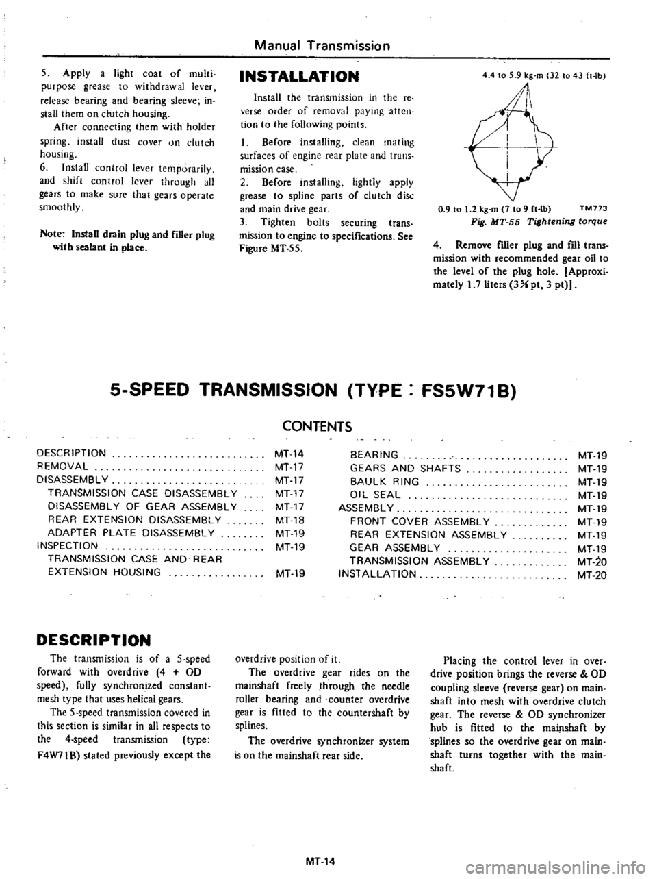
1
Before
installing
dean
mating
surfaces
of
engine
rear
plate
and
trans
mission
case
2
Before
installing
lightly
apply
grease
to
spline
parts
of
clutch
disc
and
main
drive
gear
3
Tighten
bolts
securing
trans
mission
to
engine
to
specifications
See
Figure
MT
55
5
SPEED
TRANSMISSION
TYPE
DESCRIPTION
REMOVAL
DISASSEMBL
Y
TRANSMISSION
CASE
DISASSEMBLY
DISASSEMBL
Y
OF
GEAR
ASSEMBLY
REAR
EXTENSION
DISASSEMBLY
ADAPTER
PLATE
DISASSEMBLY
INSPECTION
TRANSMISSION
CASE
AND
REAR
EXTENSION
HOUSING
DESCRIPTION
The
transmission
is
of
a
5
speed
forward
with
overdrive
4
OD
speed
fully
synchronized
constant
mesh
type
that
uses
helical
gears
The
5
speed
transmission
covered
in
this
section
is
similar
in
all
respects
to
the
4
speed
transmission
type
F4W71B
stated
previously
except
the
CONTENTS
MT14
MT17
MT17
MT17
MT17
MT18
MT19
MT19
4
4
to
5
9
kg
m
32
to
43
ft
Ib
1
0
9
to
1
2
kg
m
7
to
9
rt
lb
TM773
Fig
MT
55
Tightening
torque
4
Remove
filler
plug
and
fIll
trans
mission
with
recommended
gear
oil
to
the
level
of
the
plug
hole
Approxi
mately
I
7
liters
3
pt
3
pt
FS5W71B
BEARING
GEARS
AND
SHAFTS
BAULK
RING
OIL
SEAL
ASSEMBL
Y
FRONT
COVER
ASSEMBLY
REAR
EXTENSION
ASSEMBLY
GEAR
ASSEMBLY
TRANSMISSION
ASSEMBLY
INSTALLATION
MT19
overdrive
position
of
it
The
overdrive
gear
rides
on
the
mainshaft
freely
through
the
needle
roller
bearing
and
counter
overdrive
gear
is
fitted
to
the
countershaft
by
splines
The
overdrive
synchronizer
system
is
on
the
mainshaft
rear
side
MT14
MT19
MT19
MT19
MT19
MT19
MT19
MT19
MT19
MT
20
MT20
Placing
the
control
lever
in
over
drive
position
brings
the
reverse
OD
coupling
sleeve
reverse
gear
on
main
shaft
into
mesh
with
overdrive
clutch
gear
The
reverse
OD
synchronizer
hub
is
fItted
to
the
mainshaft
by
splines
so
the
overdrive
gear
on
main
shaft
turns
together
with
the
main
shaft
Page 266 of 537
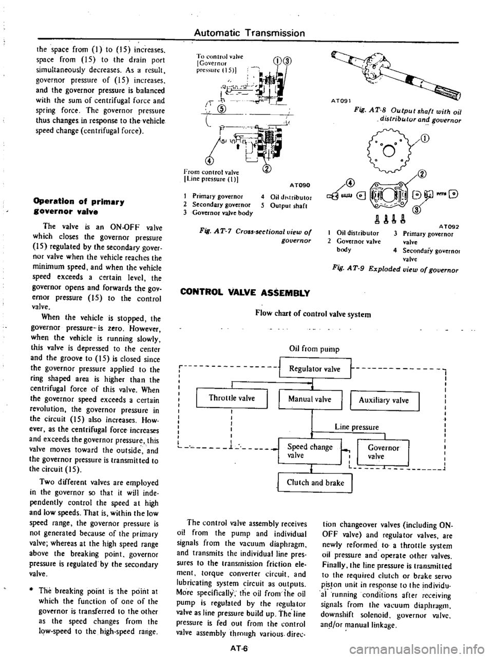
the
space
from
I
to
IS
increases
space
from
15
to
the
drain
port
simultaneously
decreases
As
a
resull
governor
pressure
of
15
increases
and
the
governor
pressure
is
balanced
with
the
sum
of
centrifugal
force
and
spring
force
The
governor
pressure
thus
changes
in
response
to
the
vehicle
speed
change
centrifugal
force
Operation
of
prlmar
governor
valve
The
valve
is
an
ON
OFF
valve
which
closes
the
governor
pressure
IS
regulated
by
the
secondary
gover
nor
valve
when
the
vehicle
reaches
the
minimum
speed
and
when
the
vehicle
speed
exceeds
a
certain
level
the
governor
opens
and
forwards
the
gov
ernor
pressure
15
to
the
control
valve
When
the
vehicle
is
stopped
the
governor
pressure
is
zero
However
when
the
vehicle
is
running
slowly
this
valve
is
depressed
to
Ihe
center
and
the
groove
to
15
is
closed
since
the
governor
pressure
applied
to
the
ring
shaped
area
is
higher
than
the
centrifugal
force
of
this
valve
When
the
governor
speed
exceeds
a
certain
revolution
the
governor
pressure
in
the
circuit
15
also
increases
How
ever
as
the
centrifugal
force
increases
and
exceeds
the
governor
pressure
this
valve
moves
toward
the
outside
and
the
governor
pressure
is
transmitted
to
the
circuil
5
Two
different
valves
are
employed
in
the
governor
so
that
it
will
inde
pendently
control
the
speed
at
high
and
low
speeds
That
is
within
the
low
speed
range
the
governor
pressure
is
not
generated
because
of
the
primary
valve
whereas
at
the
high
speed
range
above
the
breaking
point
governor
pressure
is
regulated
by
the
secondary
valve
The
breaking
point
is
the
point
at
which
the
function
of
one
of
the
governor
is
transferred
to
the
other
as
the
speed
changes
from
the
low
speed
to
the
high
speed
range
Automatic
Transmission
To
onlml
valve
l
Governor
pre
S1I
1I5
j
I
Q
J
J
f
1
1
CID
l
l
m
Line
pressure
t
D@
I
Primary
governor
2
Secondary
governor
3
Governor
valve
body
AT090
4
Oil
di
lributor
5
Output
sh
lft
Fig
AT
7
Cr05s
sectionallliew
of
governor
CONTROL
VALVE
ASSEMBLY
Ai09
Fig
AT
S
Output
shaft
with
oil
distributor
and
overnor
r
@
@
0
aBUlllI8
iUQlli
V
JlAU
I
Oil
distributor
2
Governor
nlve
body
A
T092
3
Primary
governor
valve
4
Secondary
governol
valve
Fig
A
T
9
Exploded
view
of
governor
Flow
cbar
of
control
valve
system
Oil
from
pump
Regulator
valve
1
I
i
j
Throttle
valve
I
I
l
Manual
valve
I
I
I
I
I
I
I
L
n
L
j
Speed
change
valve
I
I
t
t
I
I
I
I
I
I
Governor
I
I
valve
I
I
I
L
L
1
II
Auxiliary
valve
Line
pressure
j
Clutch
and
brake
The
control
valve
assembly
receives
oil
from
the
pump
and
individual
signals
from
the
vacuum
diaphragm
and
transmits
the
individual
line
pres
sures
to
the
transmission
friction
ele
ment
torque
converter
circuit
and
lubricating
system
circuit
as
outputs
More
specifically
the
oil
from
the
oil
pump
is
regulated
by
the
regulator
valve
as
line
pressure
build
up
the
line
pressure
is
fed
out
from
the
control
valve
assembly
through
various
direc
AT
6
tion
changeover
valves
including
ON
OFF
valve
and
regulator
valves
are
newly
reformed
to
a
throllle
system
oil
pressure
and
operate
other
valves
Finally
the
line
pressure
is
transmilled
to
the
required
dutch
or
brake
servo
pisJon
unit
in
response
to
the
individu
af
running
conditions
after
re
ejving
signals
from
the
va
uum
diaphragm
downshift
solenoid
governor
V
dlvc
and
or
manual
linkage
Page 268 of 537
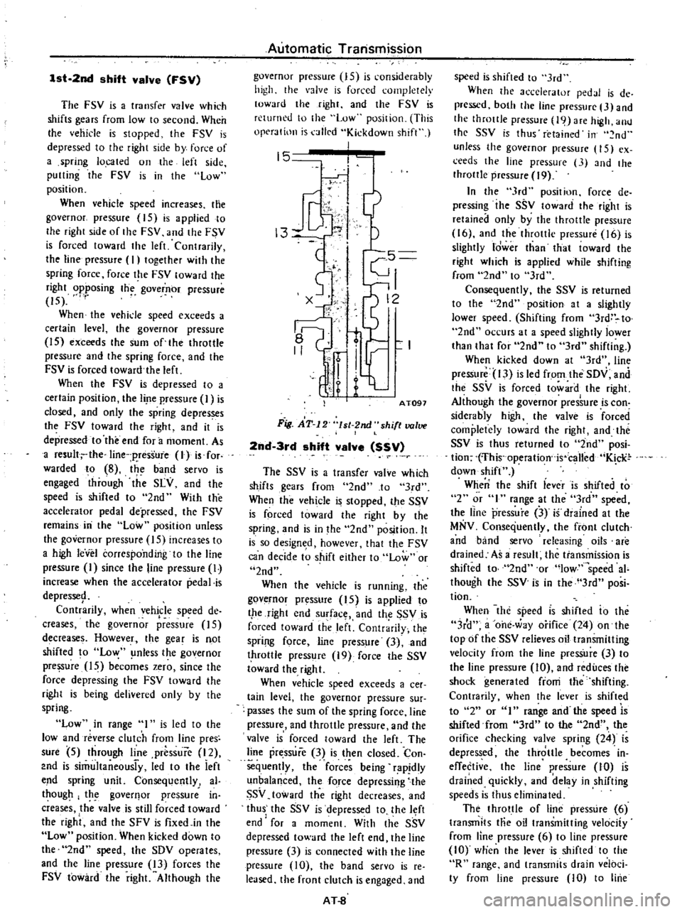
1st
2nd
shift
valve
FSV
The
FSV
is
a
transfer
valve
which
shifts
gears
from
low
to
second
When
Ihe
vehicle
is
stopped
the
FSV
is
depressed
to
the
right
side
by
force
of
a
spring
located
on
the
left
side
putting
the
FSV
is
in
the
low
position
When
vehicle
speed
increases
the
governor
pressure
15
is
applied
to
Ihe
right
side
of
the
FSV
and
the
FSV
is
forced
toward
the
left
Contrarily
the
line
pressure
I
togelher
with
the
spring
force
force
the
FSV
toward
the
right
opposing
the
governor
pressure
15
When
the
vehide
speed
exceeds
a
certain
level
the
governor
pressure
15
exceeds
the
sum
of
the
throttle
pressure
and
Ihe
spring
force
and
the
FSV
is
forced
toward
the
left
When
the
FSV
is
depressed
10
a
certain
position
the
lire
pressure
I
is
closed
and
only
the
spring
depresses
the
FSV
toward
the
right
and
it
is
depressed
to
the
end
for
a
moment
As
a
resull
the
line
p
ressure
lJ
is
for
warded
to
8
the
band
servo
is
engaged
through
the
SLY
and
the
speed
is
shifted
to
2nd
With
the
accelerator
pedal
depressed
the
FSV
remains
iIi
the
Low
position
unless
the
governor
pressure
IS
increases
to
a
high
leVel
corresponding
to
the
line
pressure
I
since
the
line
pressure
I
increase
when
the
accelerator
pedal
is
depresse9
Contrarily
when
vehicle
speed
de
creases
the
governor
pressure
15
decrease
Howeve
f
the
gear
is
not
shifted
to
Low
nless
the
governor
pressure
15
becomes
zero
since
the
force
depressing
the
FSV
toward
the
right
is
being
delivered
only
by
the
spring
Low
in
range
I
is
led
to
the
low
and
reverse
clutch
from
line
pres
sure
5
through
line
prbssure
12
2nd
is
simultaneousi
y
led
to
the
ieft
end
spring
unit
Consequently
al
thougp
the
goverflor
pressure
in
creases
the
valve
is
still
forced
toward
the
right
and
the
SFV
is
fixedjn
the
Low
position
When
kicked
down
to
the
2nd
speed
the
SDV
operates
and
the
line
pressure
13
forces
the
FSV
toward
the
right
Although
the
Automatic
Transmission
governor
pressure
15
is
considerably
high
the
valve
is
forced
completely
toward
the
right
and
the
FSV
is
returned
to
the
Low
position
This
operation
is
alled
Kickdown
shift
15
j
13
1
c5
I
0
t
r
I
I
q
1
AT091
Fig
AT
12
lsl
2nd
shift
valve
2nd
3rd
shift
valve
SSV
The
SSV
is
a
transfer
valve
which
shifts
gears
from
2nd
to
3rd
When
the
vehicle
is
stopped
the
SSV
is
forced
toward
the
right
by
the
spring
and
is
in
the
2nd
position
It
is
so
design
d
however
that
the
FSV
can
decide
to
shift
either
to
Low
or
2nd
When
the
vehicle
is
running
the
governor
pressure
15
is
applied
to
the
right
end
surface
and
th
SSV
is
forced
toward
the
left
Contrarily
the
Spri
l
force
line
pressure
3
and
throttle
press
re
19
force
the
SSV
toward
the
right
When
vehicle
speed
exceeds
a
cee
tain
level
the
governor
pressure
sur
passes
the
sum
of
the
spring
force
line
pressure
and
throttle
pressure
and
the
valve
is
forced
toward
the
left
The
line
pressure
3
is
then
closed
Con
sequently
the
forces
being
rapjdly
unbalanced
the
force
depressing
the
SSV
toward
the
right
decreases
and
thus
the
SSV
is
depressed
to
the
l
ft
end
for
a
moment
With
Ihe
SSV
depressed
toward
the
left
end
lhe
line
pressure
3
is
connected
with
the
line
pressure
10
the
band
servo
is
re
leased
the
front
clutch
is
engaged
and
AT
8
speed
is
shifted
to
3rd
When
the
accelerator
pedJI
is
de
prcssed
both
the
line
pressure
3
and
the
throttle
pressure
19
are
high
allll
the
SSV
is
thus
retained
in
nd
unless
the
governor
pressure
15
ex
ceeds
the
line
pressure
3
and
the
throttle
pressure
19
In
the
3rd
position
force
de
pressing
ihe
SSV
toward
the
right
is
retained
only
by
the
throttle
pressure
16
and
the
throttle
pressure
16
is
slightly
Idwer
than
that
toward
the
right
which
is
applied
while
shifting
from
2nd
to
3rd
Consequently
the
SSV
is
returned
to
the
2nd
position
at
a
slightly
lower
speed
Shifting
from
3rd
to
2nd
occurs
at
a
speed
slightly
lower
than
that
for
2nd
to
3rd
shifting
When
kicked
down
at
3rd
line
pressure
13
is
led
from
the
SDV
and
the
SSV
is
forced
toward
the
right
Although
the
governor
pres
ure
is
con
siderably
high
the
valve
is
forced
completely
loward
the
right
and
tht
SSV
is
thus
returned
to
2nd
posi
tion
fhis
operation
is
called
K
cli
down
shift
When
the
shift
iever
is
shifted
to
2
or
I
range
at
the
3rd
speed
the
line
pressure
3
if
diained
at
the
MNV
Consequently
the
front
clutch
and
band
servo
releasing
oils
are
drained
As
a
result
the
transmission
is
shifted
to
2nd
or
low
speed
ai
though
the
SSV
is
in
the
3rd
posi
tion
When
the
specd
IS
shifted
io
the
3r
1
a
one
way
orifice
24
on
the
topof
the
SSV
relieves
oil
transmitting
velocity
from
the
line
pressure
3
to
the
line
pressure
10
and
reduces
the
shock
generated
fioni
the
shifting
Contrarily
when
the
lever
is
shifted
to
2
or
I
range
and
the
speed
is
shifted
from
3rd
to
the
2nd
the
orifice
checking
valve
spring
24
is
depressed
the
throttle
becomes
in
effective
the
line
pressure
10
is
drained
quickly
and
delay
in
shifting
speeds
is
thus
eliminated
The
throttle
of
line
pressure
6
transmits
Hie
oil
transmitting
velocity
from
line
pressure
6
to
line
pressurc
10
wtien
the
lever
is
shifted
to
the
R
range
and
transmits
drain
veloci
ty
from
line
pressure
10
to
line
Page 269 of 537

3
Jit
f
ng
valve
24
1
3
L
l
r
I
Js
I
i
ilr
t
pressure
6
when
shif
ing
from
3rd
to
2nd
at
D
range
Thus
the
throttle
of
line
pressure
6
reduces
the
shock
generated
fro
shifting
A
plug
in
the
SSV
left
end
readjust
the
throttle
piessu
e
I
6
which
varies
depending
on
the
engine
throttle
con
dition
to
a
throttle
pressure
19
suiled
to
the
sp
ed
change
control
Moreover
the
plug
is
a
valve
which
applies
line
P
esspre
13
in
lieu
of
the
throttle
pressure
to
the
SSV
and
the
FSV
when
kickdowri
is
performed
When
the
throttle
pressure
16
is
applied
to
the
left
side
of
this
plug
and
the
plug
is
epressed
toward
the
right
a
slight
space
is
formed
from
the
throttle
pressure
6
10
19
A
throt
tIepressu
19
w
1iFh
is
lower
by
the
pressure
loss
equivalent
to
this
space
is
rH
1
Pressure
Odifier
valve
PMV
I
Compared
to
the
operating
pressure
required
in
starting
th
vehicle
the
ppwer
trimsinitting
capacity
of
the
clutch
that
is
required
operating
pres
sure
may
be
lower
when
the
vehicle
is
once
started
When
the
line
pressure
is
retained
at
a
high
level
up
to
a
high
vehicle
speed
shock
gerieraled
from
the
shirring
increases
arid
the
oil
pump
loss
also
jncrdases
In
order
to
prevent
his
the
t
lrott
le
pressure
must
be
l
hanged
over
with
the
operation
of
the
governor
pressure
15
to
reduce
Ihe
line
pressure
The
PMV
is
used
for
this
purposc
Automatic
Transmission
generated
the
piessure
loss
is
adde
d
to
the
spring
force
and
the
plug
is
lhus
forced
back
from
the
right
to
the
left
When
this
pressure
19
increases
ex
cessively
the
plug
is
further
depressed
toward
the
left
space
from
the
lhrot
tle
pressure
19
to
the
drain
circuit
13
increases
and
the
throttle
press
ure
19
decreases
Thus
the
plug
is
balanced
imd
the
throttle
pressure
19
is
reduced
to
Ii
certain
value
against
the
throttle
pressure
6
Wheri
performing
kickdowri
the
SDV
moves
a
high
line
pressure
is
led
to
the
circuit
19
from
the
line
pressure
circuit
13
which
had
been
drained
the
plug
is
forced
toward
the
left
and
circuit
19
becomes
equal
to
the
line
pressure
13
I
W
15
I
A
TOgS
Fig
iT
13
2nd
3rd
shift
vallJe
I
When
the
governor
pressuie
IS
which
is
applied
to
the
right
side
of
the
PMV
is
low
the
valve
is
forced
toward
the
right
by
the
throttle
ines
sure
16
applied
to
the
area
differ
ence
of
the
value
and
the
spring
foice
and
t
he
circuit
from
circuit
16
to
circuit
18
is
closed
However
when
vehicle
speed
increases
andl
the
gaver
nor
pressure
15
exceeds
a
certain
level
the
governor
pressure
toward
the
left
which
is
applied
to
the
right
side
exceeds
the
spring
force
and
the
throt
tle
pressure
16
toward
thc
right
the
valve
is
depressed
loward
the
lefi
and
the
throttle
pressure
is
led
from
circuit
AT
9
16
to
circuit
18
This
throttle
pressure
18
is
applied
to
the
top
of
the
PRV
and
the
force
of
the
line
pressure
source
7
is
reduced
Contra
rily
when
the
vehicle
speed
decreases
arid
the
governor
ipressure
15
de
creases
the
force
toward
the
fight
exceeds
ithe
governor
pressure
the
valve
is
forced
back
toward
the
right
and
the
throttle
pressure
18
is
drained
to
the
spring
unit
This
valve
is
sWitched
when
the
throttle
pressure
and
the
governor
pressure
are
high
or
when
tIiey
are
both
Tow
i
i
I
11
18
16
n
r
I
I
15
AT099
Fig
AT
14
Pre
ure
modifier
valve
Vacuum
thro
le
valve
VTV
The
vacuum
t
rottle
valve
is
a
regula
tor
valve
whiCh
uses
the
line
pressure
7
for
the
pressure
source
and
regulates
the
throttle
pressure
16
I
which
is
proportioned
t
the
force
of
the
vacuum
diaphragm
The
vacuum
dia
phragm
yories
depending
on
the
engine
throt
le
condition
negative
pressure
in
the
inta
e
line
When
the
line
pressure
7
is
ap
plied
to
the
bottom
through
the
valve
hole
and
the
v
a
ve
is
forced
upward
space
from
the
line
pressure
7
to
the
throttle
pressure
16
is
dosed
and
the
space
from
the
Ihrottle
pressure
16
to
the
drain
circuit
17
is
about
to
open
In
this
operation
the
throttle
pressure
16
becomes
lower
than
the
linep
s
ureY
btthe
p
e
sur
9
iv
alenl
of
the
loss
of
space
and
Ihe
force
depressing
tlie
rod
if
the
vaeuum
diaphragm
is
balanced
wit
Ii
thethrot
tie
pressure
16
a
pplied
upward
tOlthe
bottom
When
the
erigine
torque
is
high
Ihe
negative
pressure
in
the
intake
iirie
rises
tending
ioward
atmospheric
pressure
and
the
force
of
the
rod
to
depress
the
valve
increases
As
a
result
the
valve
is
depressed
downward
the
Page 271 of 537

2nd
3rd
timln
valve
TMV
This
valve
is
a
transfer
valve
which
switches
the
by
pass
circuit
of
the
orifice
22
in
the
front
clutch
pres
sure
circuit
II
in
response
to
vehicle
speed
and
throttle
condition
A
force
created
when
the
governor
pressure
IS
is
applied
to
the
bottom
of
the
TMV
constitutes
the
upward
force
and
a
force
created
when
the
spring
force
and
the
throttle
pressure
are
applied
to
the
top
of
the
TMV
consti
tutes
the
downward
force
When
the
throttle
pressure
16
is
lower
than
the
governor
pressure
IS
Automatic
Transmission
the
upward
force
exceeds
the
down
ward
force
the
valve
is
locked
upward
and
passage
from
circuit
l0
2nd
from
the
Top
to
circuit
II
is
closed
Consequently
the
line
pressure
10
is
led
to
the
front
clutch
circuit
II
through
the
orifice
22
and
the
oil
pressure
is
thus
transmitted
slowly
However
under
normal
shifting
the
throttle
pressure
16
has
a
pressure
exceeding
a
certain
level
and
the
downward
force
e
xceeds
the
upward
force
As
a
result
the
valve
is
locked
downward
the
passage
from
circuit
10
to
circuit
II
is
opened
and
the
orifice
22
is
bypassed
ATll
AT104
Fig
JlT
19
2nd
3rd
timing
valve
Page 298 of 537
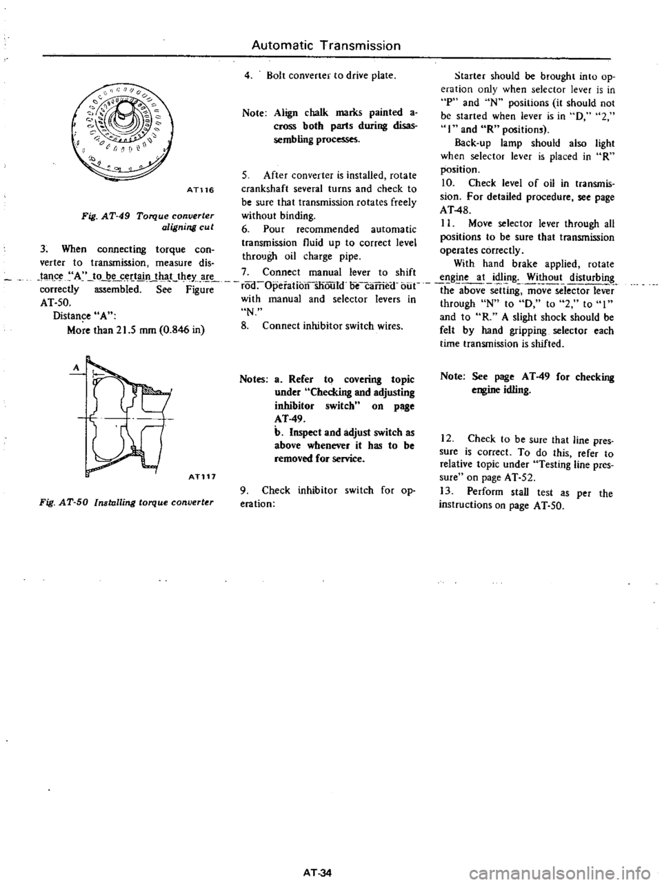
Starter
should
be
brought
into
op
eration
only
when
selector
lever
is
in
P
and
N
positions
it
should
not
be
started
when
lever
is
in
D
2
I
and
R
positions
Back
up
lamp
should
also
light
when
selector
lever
is
placed
in
R
position
S
After
converter
is
installed
rotate
10
Check
level
of
oil
in
transmis
crankshaft
several
turns
and
check
to
be
sure
that
transmission
rotates
freely
sion
For
detailed
procedure
see
page
AT48
without
binding
6
Pour
recommended
automatic
II
Move
selector
lever
through
aU
positions
to
be
sure
that
transmission
transmission
fluid
up
to
correct
level
operates
correctly
through
oil
charge
pipe
verter
to
transmission
measure
dis
With
hand
brake
applied
rotate
tan
A
to
be
certain
that
they
are
7
Connect
manual
lever
to
shift
engine
at
idling
Without
disturbing
correctly
mbi
d
S
F
rod
Opeiationsliould
oecaTrie
f
bue
the
above
sclUng
ffiovTSelector
lever
AT
50
with
manual
and
selector
levers
in
through
N
to
D
to
2
to
I
Distance
A
N
and
to
R
A
slight
shock
should
be
More
than
21
5
mm
0
846
in
8
Connect
inhibitor
switch
wires
felt
by
hand
gripping
selector
each
time
transmission
is
shifted
Automatic
Transmission
4
Bolt
converter
to
drive
plate
Note
Align
chalk
marks
painted
a
cross
both
parts
during
disas
sembling
processes
AT116
Fig
AT
49
Torque
converter
aligning
cu
t
3
When
connecting
torque
can
A
ATl17
Notes
a
Refer
to
covering
topic
under
Checking
and
adjusting
inhibitor
switch
n
on
page
AT
49
b
Inspect
and
adjust
switch
as
above
whenever
it
has
to
be
removed
for
service
Fig
AT
50
Installing
torque
converter
9
Check
inhibitor
switch
for
op
eration
AT
34
Note
See
page
AT
49
for
checking
engine
idling
12
Check
to
be
sure
that
line
pres
sure
is
correct
To
do
this
refer
to
relative
topic
under
Testing
line
pres
sure
on
page
AT
52
13
Perform
stall
test
as
per
the
instructions
on
page
AT
50