ECU DATSUN PICK-UP 1977 Service Manual
[x] Cancel search | Manufacturer: DATSUN, Model Year: 1977, Model line: PICK-UP, Model: DATSUN PICK-UP 1977Pages: 537, PDF Size: 35.48 MB
Page 10 of 537
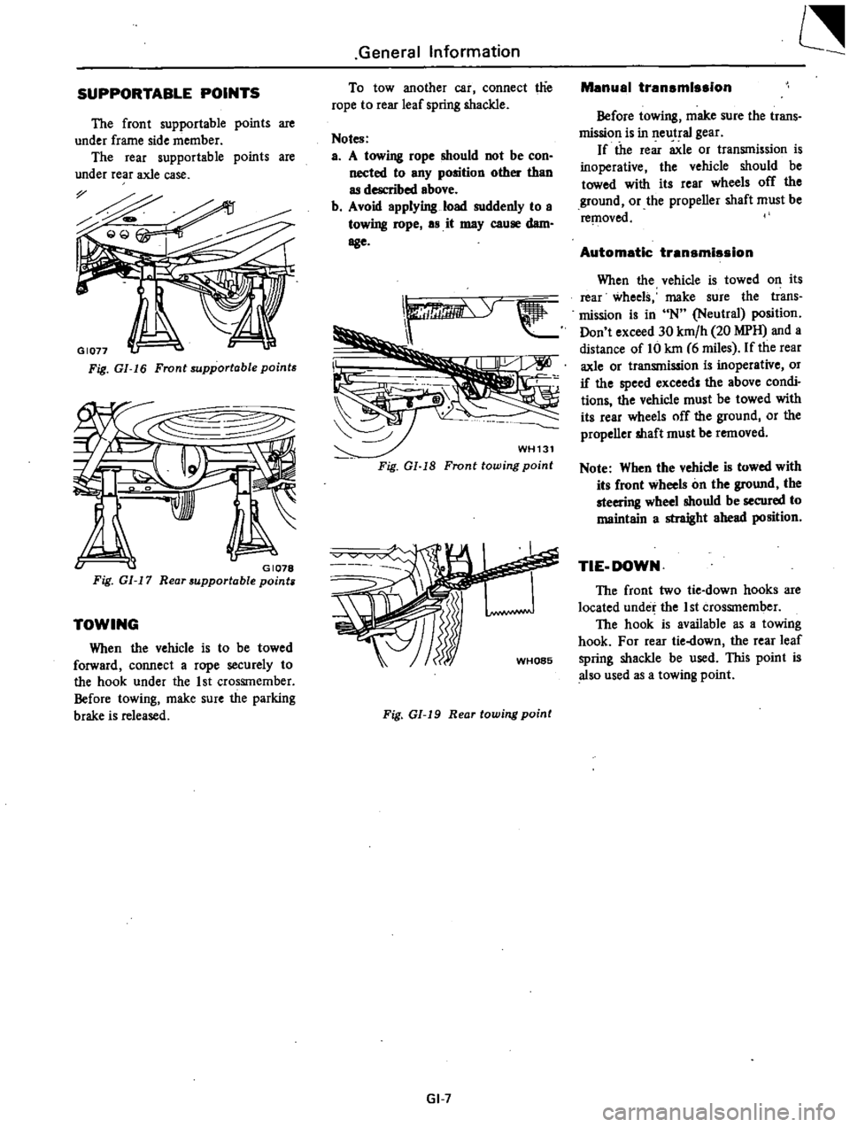
SUPPORTABLE
POINTS
The
front
supportable
points
are
under
frame
side
member
The
rear
supportable
points
are
under
rear
axle
case
Fig
GI
16
Front
supportable
points
v
GI078
Fig
GI
17
Rear
supportable
points
TOWING
When
the
vehicle
is
to
be
towed
forward
connect
a
rope
securely
to
the
hook
under
the
1st
CrosSIn
ember
Before
towing
make
sure
the
parking
brake
is
released
General
Information
To
tow
another
car
connect
t1ie
rope
to
rear
leaf
spring
shackle
Notes
a
A
towing
rope
should
not
be
con
nected
to
any
position
other
than
as
described
above
b
Avoid
applying
load
suddenly
to
a
towing
rope
as
it
may
cause
dam
age
WH131
Fig
Gl
18
Fronttowing
point
Fig
01
19
Rear
towing
point
GI
7
Manual
transmission
Before
towing
make
sure
the
trans
mission
is
in
neutral
gear
If
the
rear
axle
or
transmission
is
inoperative
the
vehicle
should
be
towed
with
its
rear
wheels
off
the
ground
or
the
propeller
shaft
must
be
re
l1oved
Automatic
transmission
When
the
vehicle
is
towed
on
its
rear
wheels
make
sure
the
trans
mission
is
in
N
Neutral
position
Don
t
exceed
30
km
h
20
MPH
and
a
distance
of
Hi
kin
6
miles
If
the
rear
axle
or
transmission
is
inoperative
or
if
the
speed
exceed
the
above
condi
tions
the
vehicle
must
be
towed
with
its
rear
wheels
off
the
ground
or
the
propeller
shaft
must
be
removed
Note
When
the
vehicle
is
towed
with
its
front
wheels
on
the
ground
the
steering
wheel
shouId
be
secured
to
maintain
a
straight
ahead
position
TIE
DOWN
The
front
two
tie
down
hooks
are
located
under
the
1st
crosSInember
The
hook
is
available
as
a
towing
hook
For
rear
tie
down
the
rear
leaf
spring
shackle
be
used
lIDs
point
is
also
used
as
a
towing
point
Page 19 of 537
Engine
Tune
up
BASIC
MECHANICAL
SYSTEM
ADJUSTING
INTAKE
AND
EXHAUST
VALVE
CLEARANCE
CHECKING
AND
ADJUSTING
DRIVE
BELT
RETIGHTENING
CYLINDER
HEAD
BOLTS
MANIFOLD
NUTS
AND
CARBURETOR
SECURING
NUTS
CHECKING
ENGINE
OIL
REPLACING
OIL
FILTER
CHANGING
ENGINE
COOLANT
ADJUSTING
INTAKE
AND
EXHAUST
VALVE
CLEARANCE
Note
After
tightening
cylinder
head
bolts
adjust
intake
and
exhaust
valve
clearances
Valve
clearance
adjustment
is
impossible
when
the
engine
is
in
oper
ation
1
Loosen
pivot
locking
nu
t
and
turn
pivot
screw
until
the
specified
clearance
is
obtained
while
cold
Using
service
tool
tighten
pivot
locking
nut
securely
after
adjustment
and
recheck
the
clearance
2
Warm
up
engine
for
at
least
several
minutes
and
stop
it
Measure
valve
clearance
while
hot
If
out
of
specifications
adjust
Unit
mm
in
Intake
0
20
0
008
Cold
Exhaust
0
25
0
010
Intake
0
25
OmO
Wann
I
Exhaust
0
30
0
012
STl
064000
I
ET009
Fig
ET
5
Adjusting
valve
clearance
CONTENTS
ET
7
PERMANENT
ANTI
FREEZE
COOLANT
CHECKING
COOLING
SYSTEM
HOSES
AND
CONNECTIONS
INSPECTION
OF
RADIATOR
CAP
COOLING
SYSTEM
PRESSURE
TEST
CHECKING
VACUUM
FITTINGS
HOSES
AND
CONNECTIONS
CHECKING
ENGINE
COMPRESSION
COMPRESSION
PRESSURE
TEST
TEST
RESULT
ET
7
ET7
ET
B
ET
B
ET
B
CHECKING
AND
ADJUSTING
DRIVE
BELT
ET
B
ET
B
ET
B
ET
B
ET
B
ET
9
ET
9
ET
9
2
Normal
drive
belt
deflection
is
8
to
12
mm
0
315
to
0
472
in
when
moderate
thumb
pressure
is
applied
midway
between
pulleys
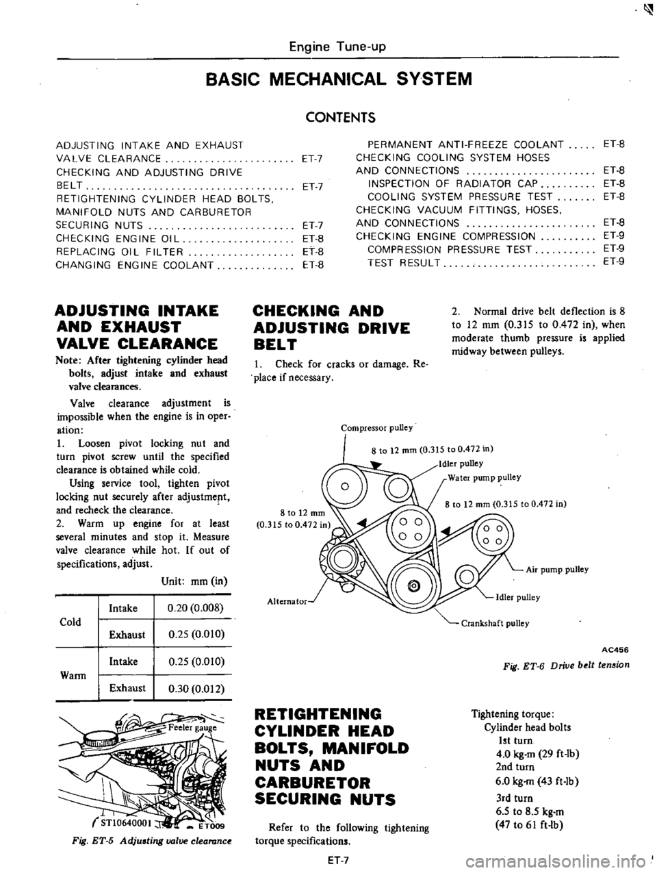
1
Check
for
cracks
or
damage
Re
place
if
necessary
Compressor
pulley
8
to
12
mm
0
315
to
0
472
in
Idler
pulley
Water
pump
pulley
8
to
12
mm
0
315
to
0
472
in
Air
pump
pulley
Alternator
AC456
Fig
ET
6
Driue
belt
tension
RETIGHTENING
CYLINDER
HEAD
BOLTS
MANIFOLD
NUTS
AND
CARBURETOR
SECURING
NUTS
Tightening
torque
Cylinder
head
bolts
1st
turn
4
0
kg
m
29
ft
Ib
2nd
turn
6
0
kg
m
43
ft
Ib
3rd
turn
6
5
to
8
5
kg
m
47
to
61
ft
lb
Refer
to
the
following
tightening
torque
specifications
ET
7
Page 59 of 537
Engine
Mechanical
Standard
Wear
limit
Inner
diameter
85
000
to
85
050
0
2
0
0079
3
3465
to
3
3484
Cylinder
bore
mm
in
Out
of
round
O
ot5
0
0006
Taper
0
015
0
0006
Difference
in
cylinder
bore
0
05
0
0020
0
2
0
0079
mm
in
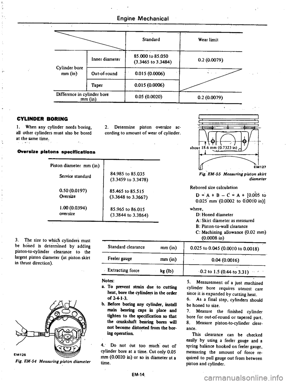
CYLINDER
BORING
I
When
any
cylinder
needs
boring
all
other
cylinders
must
also
be
bored
at
the
same
time
Oversize
pistons
spec
Hic
etlons
Piston
diameter
mm
in
Servioe
standard
0
50
0
0197
Oversize
1
00
0
0394
oversize
3
The
size
to
which
cylinders
must
be
honed
is
determined
by
adding
piston
to
cylinder
clearance
to
the
largest
piston
diameter
at
piston
skirt
in
thrust
direction
EM126
Fig
EM
54
Measuring
piston
diamet
r
2
Determine
piston
oversize
ac
cording
to
amount
of
wear
of
cylinder
84
985
to
85
035
3
3459
to
3
3478
85
465
to
85
515
3
3648
to
3
3667
85
965
to
86
015
3
3844
to
3
3864
Standard
clearance
ffim
in
Feeler
gauge
mm
in
Extracting
force
kg
Ib
Notes
a
To
prevent
strain
due
to
cutting
heat
bore
the
cylinders
in
the
order
of
2
4
1
3
b
Before
boring
any
cylinder
install
main
bearing
caps
in
place
and
tighten
to
the
specification
so
that
the
crankshaft
bearing
bores
will
not
become
distorted
from
the
bor
ing
operation
4
Do
not
cut
too
much
out
of
cylinder
bore
at
a
time
Cut
only
0
05
mm
0
0020
in
or
so
in
diameter
at
a
time
EM
14
L
7
A
aboull
6
m
o
7323in
r
127
Fig
EM
55
MeCUJlJring
piston
skirt
diameter
Rebored
size
calculation
o
A
B
C
A
0
005
to
0
Q25
mm
0
0002
to
0
0010
in
where
D
Honed
diameter
A
Skirt
diameter
as
measured
B
Piston
to
wall
clearance
C
Machining
allowance
0
02
mm
0
0008
in
0
025
to
0
045
0
0010
to
0
0018
0
04
0
0016
0
2
to
1
5
O
44
to
3
31
5
Measurement
of
a
just
machined
cylinder
bore
requires
utmost
care
since
it
is
expanded
by
cutting
heat
6
As
a
final
step
cylinders
should
be
honed
to
size
7
Measure
the
finished
cylinder
bore
for
out
of
round
or
tapered
part
8
Measure
piston
to
cylinder
clear
ance
This
clearance
can
be
checked
easily
by
using
a
feeler
gauge
and
a
spring
balance
hooked
on
feeler
gauge
measuring
the
amount
of
force
re
quired
to
pull
gauge
out
from
between
piston
and
cylinder
Page 67 of 537
5
Install
rocker
arms
by
pressing
valve
springs
down
with
a
screwdriver
6
Install
valve
rocker
springs
7
After
assembling
cylinder
head
turn
camshaft
until
No
I
piston
is
at
T
D
C
on
its
compression
stroke
EM1S5
Fig
EM
83
A
embling
cylinder
head
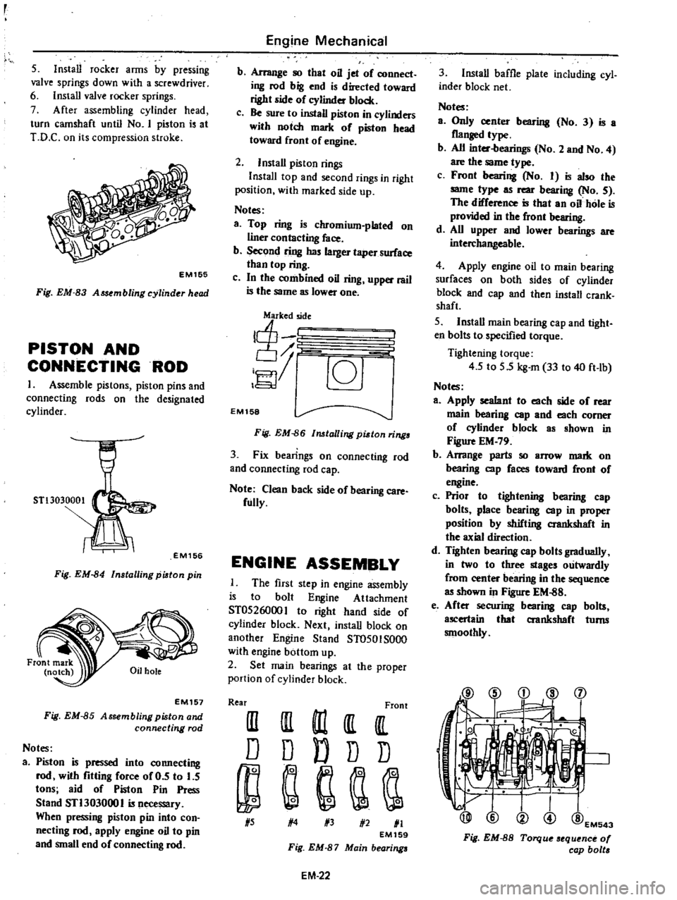
PISTON
AND
CONNECTINGROD
1
Assemble
pistons
piston
pins
and
connecting
rods
on
the
de
ignated
cylinder
STl3030001
EM156
Fig
EM
84
Installing
piston
pin
EM157
Fig
EM
85
Assembling
piston
and
connecting
rod
Notes
a
Piston
is
pressed
into
connecting
rod
with
fitting
force
of
0
5
to
5
tons
aid
of
Piston
Pin
Press
Stand
STl303000
I
is
necessary
When
pressing
piston
pin
into
con
necting
rod
apply
engine
oil
to
pin
and
small
end
of
connecting
rod
Engine
Mechanical
b
Arrange
so
that
oil
jet
of
connect
ing
rod
big
end
is
directed
toward
right
side
of
eylinder
block
c
Be
sure
to
install
piston
in
cylinders
with
notch
mark
of
piston
head
toward
front
of
engine
2
Install
piston
rings
InstalI
top
and
second
rings
in
right
position
with
marked
side
up
Notes
a
Top
ring
is
chromium
plated
on
liner
contacting
face
b
Second
ring
has
larger
taper
surface
than
top
ring
c
In
the
combined
oil
ring
upper
rail
is
the
same
as
lower
one
j
c6J
EM158
Fig
EM
86
lalling
pidon
rings
3
Fix
bearings
on
connecting
rod
and
connecting
rod
cap
Note
Clean
back
side
of
bearing
care
fully
ENGINE
ASSEMBLY
The
first
step
in
engine
assembly
is
to
bolt
Engine
Attachment
ST0526000
I
to
right
hand
ide
of
cylinder
block
Next
install
block
on
another
Engine
Stand
ST0501S000
with
engine
bottom
up
2
Set
main
bearings
at
the
proper
portion
of
cylinder
block
Rear
Front
III
III
m
It
IlL
D
D
D
D
D
1
5
1
4
1
3
1
2
1
1
EM159
Fig
EM
87
Main
bearings
EM
22
3
Install
baffle
plate
including
cyl
inder
block
net
Notes
a
Only
center
bearing
No
3
is
a
flanged
type
b
All
inter
bearings
No
2
and
No
4
are
the
same
type
c
Front
bearing
No
I
is
also
the
same
type
as
rear
bearing
No
5
The
difference
is
that
an
oil
hole
is
provided
in
the
front
bearing
d
All
upper
and
lower
bearings
are
interchangeable
4
Apply
engine
oil
to
main
bearing
surfaces
on
both
sides
of
cylinder
block
and
cap
and
then
install
crank
shaft
5
Install
main
bearing
cap
and
tight
en
bolts
to
specified
torque
Tightening
torque
4
5
to
5
5
kg
m
33
to
40
ft
lb
Notes
a
Apply
sealant
to
each
side
of
rear
main
bearing
cap
and
each
comer
of
eylinder
block
as
shown
in
Figure
EM
79
b
Arrange
parts
so
arrow
mark
on
bearing
cap
faces
toward
front
of
engine
c
Prior
to
tightening
bearing
cap
bolts
place
bearing
cap
in
proper
position
by
shifting
crankshaft
in
the
axial
direction
d
Tighten
bearing
cap
bolts
gradually
in
two
to
three
stages
outwardly
from
center
bearing
in
the
sequence
as
shown
in
Figure
EM
88
e
After
securing
bearing
cap
bolts
ascertain
that
aankshaft
turns
smoothly
@
i
d
l
j
1
@EM543
Fig
EM
8S
Torque
sequence
0
cap
bolt
Page 68 of 537
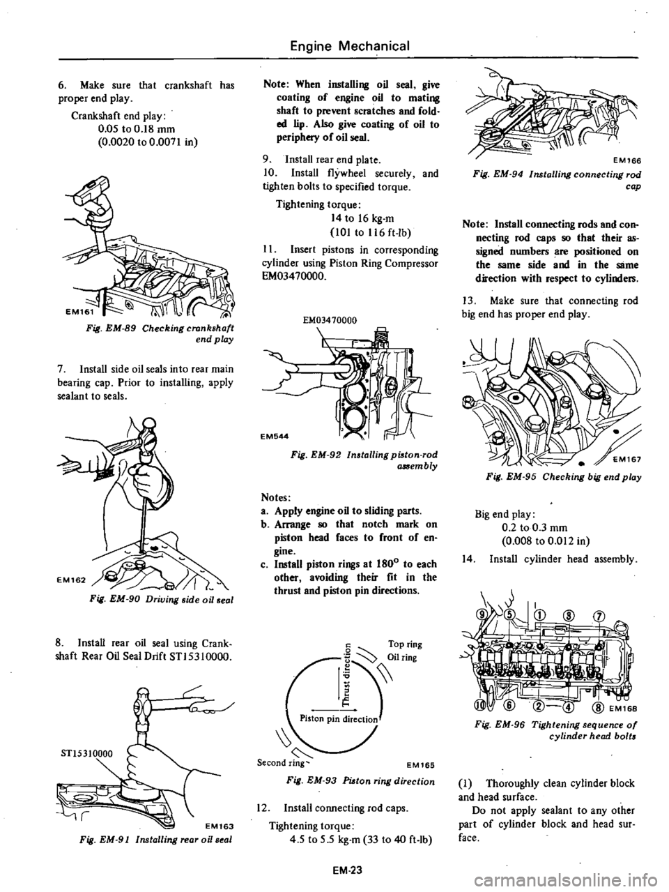
6
Make
sure
that
crankshaft
has
proper
end
play
Crankshaft
end
play
0
05
to
0
18
mm
0
0020
to
0
0071
in
Fig
EM
89
Checking
crankshaft
end
play
7
Install
side
oil
seals
into
rear
main
bearing
cap
Prior
to
installing
apply
sealant
to
seals
Fig
EM
90
Driving
side
oil
seal
8
Install
rear
oil
seal
using
Crank
shaft
Rear
Oil
Seal
Drift
STI5310000
r
STl5310000
r
EM163
Fig
EM
91
Installing
rear
oi
seal
Engine
Mechanical
Note
When
installing
oil
seal
give
coating
of
engine
oil
to
mating
shaft
to
prevent
scratches
and
fold
ed
lip
Also
give
coating
of
oil
to
periphery
of
oil
seal
9
Install
rear
end
plate
10
Install
flywheel
securely
and
tighten
bolts
to
specified
torque
Tightening
torque
14
to
16
kg
m
101
to
116
ft
lb
I
I
Insert
pistons
in
corresponding
cylinder
using
Piston
Ring
Compressor
EM03470000
EM03410000
I
EM544
Fig
EM
92
Installing
pi8ton
rod
a
Sembly
Notes
a
Apply
engine
oil
to
sliding
parts
b
Arrange
80
that
notch
mark
on
piston
head
faces
to
front
of
en
gine
c
Install
piston
rings
at
1800
to
each
other
avoiding
their
fit
in
the
thrust
and
piston
pin
directions
6
Top
ring
I
iilring
Piston
pin
ireClioJ
EM165
Fig
EM
93
PUtan
ring
direction
12
Install
connecting
rod
caps
Tightening
torque
4
5
to
5
5
kg
m
33
to
40
ft
lb
EM
23
Fig
EM
94
Installing
connecting
rod
cap
Note
Install
connecting
rods
and
con
necting
rod
caps
80
that
their
as
signed
numbers
are
positioned
on
the
same
side
and
in
the
SlIme
direction
with
respect
to
cylinders
13
Make
sure
that
connecting
rod
big
end
has
proper
end
play
Fig
EM
95
Checking
big
end
play
Big
end
play
0
2
to
0
3
mm
0
008
to
0
Ql2
in
14
Install
cylinder
head
assembly
Fig
EM
96
Tightening
sequence
01
cylinder
head
bolts
J
Thoroughly
clean
cylinder
block
and
head
surface
Do
not
apply
sealant
to
any
other
part
of
cylinder
block
and
head
sur
face
Page 70 of 537
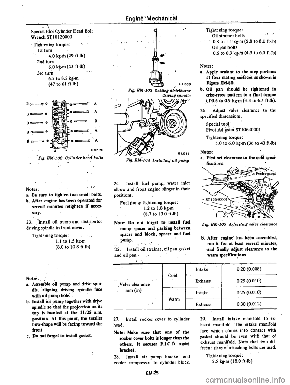
Speci
ol
Cylinder
Head
Bolt
Wren
h
8110120000
Tightening
torque
1st
turn
4
0
kg
m
29
ft
lb
2nd
turn
6
0
kg
m
43
ft
lb
3rd
turn
6
5
to
8
5
kg
m
47
to
61
ft
lb
B
O
A
A
B
A
A
B
O
B
O
R
O
EM
176
Fig
EM
I02
Cylinder
head
boll
Notes
a
Be
sure
to
tighten
two
small
bolts
b
After
engine
has
been
operated
for
several
minutes
retighten
if
neces
sary
23
Install
oil
pump
and
distr
butor
driving
spindle
in
front
cover
Tightening
torque
1
1
to
1
5
kg
m
8
0
to
10
8
ft
lb
Notes
a
Assemble
oil
pump
and
drive
spin
die
aligning
driving
spindle
face
with
oil
pump
hole
b
Install
oil
pump
together
with
drive
spindle
so
that
the
projection
on
its
top
is
located
at
the
II
25
a
m
position
At
this
point
the
smaller
bow
shape
will
be
facing
toward
the
front
c
Do
not
forget
to
install
gas
et
Engine
Mechanical
I
Fig
EM
I04
11l6lalling
oil
pump
24
Install
fuel
pump
water
inlet
elbow
and
front
engine
slinger
in
their
positions
Fuel
pump
tightening
torque
1
2
to
1
8
kg
m
8
7
to
13
0
ft
lb
Note
Do
not
forget
to
install
fuel
pump
spacer
and
packing
between
spacer
and
block
spacer
and
fuel
pump
25
Install
oil
strainer
oil
pan
gasket
and
oil
pan
27
Install
rocker
cover
to
cylinder
head
Note
Make
sure
that
one
of
the
rocker
cover
bolts
is
longer
than
the
others
It
secures
F
I
C
D
assist
bracket
28
Install
air
pump
bracket
and
cooler
compressor
to
cylinder
block
EM
25
Tightening
torque
Oil
strainer
bolts
0
8
to
I
l
kg
m
5
8
to
8
0
ft
lb
Oil
pan
bolts
0
6
to
0
9
kg
m
4
3
to
6
5
ft
lb
Notes
a
Apply
sealant
to
the
step
portions
at
four
mating
surfaces
as
shown
in
Figure
EM
80
b
Oil
pan
should
be
tigh
tened
in
criss
cross
pattern
to
a
final
torque
of
0
6
to
0
9
kg
m
4
3
to
6
5
ft
lb
26
Adjust
valve
clearance
to
the
specified
dimensions
Special
tool
Pivot
Adj
iier
STl064000l
Tightening
torque
5
0
to
6
0
kg
m
36
to
43
ft
lb
Fig
EM
I05
Adjusting
valve
clearance
b
After
engine
has
been
assembled
run
it
for
at
least
several
minutes
and
finally
adjust
clearance
to
the
warm
specifications
29
Install
intake
manifold
to
ex
haust
manifold
The
intake
manifold
face
which
comes
into
contact
with
gasket
should
be
even
with
that
of
exhaust
manifold
Note
that
two
dif
ferent
sizes
of
attaching
bolts
are
used
Tightening
torque
2
5
kg
m
18
0
ft
lb
Page 71 of 537
30
Install
heatshieid
plate
on
mani
fold
assembly
31
Install
air
gallery
pipe
on
ex
haust
manifold
32
Install
manifold
gasket
and
manifold
assembly
on
cylinder
head
Tightening
torque
1
2to
1
6kg
m
8
7
to
11
6
ft
lb
33
Install
blow
by
gas
pipe
on
cyl
inder
block
and
tighten
with
rear
engine
slinger
34
Install
thermostat
housing
gas
ket
thermostat
housing
and
thermo
stat
35
Install
thermal
vacuum
valve
on
thermostat
housing
Before
installing
apply
a
liquid
packing
slightly
to
the
threads
36
Install
FJ
C
D
bracket
on
cylin
der
head
37
Install
E
G
R
passage
and
E
G
R
valve
on
intake
manifold
38
Connect
E
G
R
tube
to
E
G
R
tube
and
exhaust
manifold
39
Install
check
valve
on
air
gallery
pipe
40
Install
air
cleaner
bracket
on
intake
manifold
41
Install
air
control
valve
on
air
cleaner
bracket
California
models
42
Install
vacuum
and
fuel
tubes
combined
on
cylinder
head
43
Install
distributor
assembly
44
Install
heatshield
plate
joint
seat
and
carburetor
Carbure10r
tightening
torque
0
5
to
1
0
kg
m
3
6
to
7
2
ft
lb
Note
When
instalUng
joint
seat
be
sure
to
put
the
duct
into
primary
hole
in
intake
manifold
S
J
Heatshield
plate
4
Joint
seat
2
Primary
hole
5
Secondary
hole
3
Duct
EM534
Fig
EM
I06
Installing
carburetor
joint
seat
Engine
Mechanical
45
Install
dash
pot
bracket
and
dash
pot
to
intake
manifold
46
Connect
all
air
vacuum
and
fuel
hoses
and
then
secure
with
clamps
I
Cylinder
block
to
P
C
V
valve
hose
2
A
B
valve
to
E
G
R
passage
vac
uum
hose
3
A
B
valve
to
E
G
R
passage
air
hose
4
Vacuum
tube
to
carburetor
vac
uum
hoses
5
Fuel
ube
to
carburetor
fuel
hose
6
Fuel
tube
to
fuel
pump
fuelhose
7
Distributor
to
vacuum
switch
or
spark
delay
valve
vacuum
hose
8
Air
control
valve
vacuum
hose
9
Check
valve
to
air
control
valve
hose
10
Thermal
vacuum
valve
to
E
G
R
valve
vacuum
hose
I
I
Thermal
vacuum
valve
to
vacuum
tube
hose
47
Install
carburetor
air
cleaner
on
carburetor
and
then
connect
air
and
vacuum
hoses
as
follows
I
Air
cleaner
to
exhaust
manifold
hot
air
duct
2
Air
c1eaner
to
air
pump
hose
3
Air
cleaner
to
rocker
cover
hose
4
Air
cleaner
to
air
control
valve
hose
5
6
48
Install
spark
plugs
in
place
49
Connect
all
distributor
high
ten
sion
cables
to
spark
plugs
50
Install
air
pump
drive
belt
cool
er
compressor
and
idler
pulley
51
Install
left
engine
mounting
bracket
52
Install
clutch
assembly
on
flywheel
with
Clutch
Aligning
Bar
KV30100200
Air
cleaner
to
A
B
valve
hose
Other
vacuum
hoses
Tightening
torque
1
2
to
2
2
kg
m
8
7
to
15
9
ft
lb
EM
26
I
I
KV30100200
EM440
Fig
EM
I07
In
talling
clutch
embly
53
Using
an
overhead
hoist
and
lifting
cable
hoist
engine
away
from
engine
stand
and
then
down
onto
engine
carrier
54
Install
right
engine
mounting
bracket
oil
filter
oil
pressure
switch
oil
level
gauge
and
water
drain
plug
When
installing
oil
filter
fasten
it
to
cylinder
block
by
hand
Note
Do
not
overtighten
flit
or
oil
leakage
may
occur
55
Install
alternator
bracket
adjust
ing
bar
alternator
cooling
fan
and
belt
56
Adjust
the
deflection
of
drive
belts
when
thumb
pressure
is
applied
midway
between
pulleys
A
pressed
force
is
above
10
kg
22
0
lb
Deflection
of
drive
belts
8
to
12
mm
0
315
to
0
472
in
EM613
Fig
EM
lOB
Fan
belt
tension
57
Fill
engine
oil
up
to
specified
level
Page 85 of 537
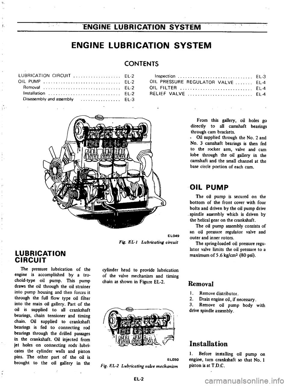
ENGINE
LUBRICATION
SYSTEM
ENGINE
LUBRICATION
SYSTEM
CONTENTS
LUBRICATION
CIRCUIT
01
L
PUMP
Removal
Installation
Disassembly
and
assembly
EL
2
EL
2
EL
2
EL
2
EL
3
Inspection
OIL
PRESSURE
REGULATOR
VALVE
OIL
FILTER
RELIEF
VALVE
EL
3
EL
4
EL
4
EL
4
E
L049
Fig
Elr
I
Lubricating
circuit
LUBRICATION
CIRCUIT
The
pressure
lubrication
of
the
engine
is
accomplished
by
a
tro
choid
type
oil
pump
This
pump
draws
the
oil
through
the
oil
strainer
into
pump
housing
and
then
forces
it
through
the
full
flow
type
oil
filter
into
the
main
oil
gallery
Part
of
the
oil
is
supplied
to
all
crankshaft
bearings
chain
tensioner
and
timing
chain
Oil
supplied
to
crankshaft
bearings
is
fed
to
connecting
rod
bearings
through
the
drilled
passages
in
the
crankshaft
Oil
injected
from
jet
holes
on
connecting
rods
Iubri
cates
the
cylinder
walls
and
piston
pins
The
other
part
of
the
oil
is
brought
to
the
oil
gallery
in
the
cylinder
head
to
provide
lubrication
of
the
valve
mechanism
and
timing
chain
as
shown
in
Figure
EL
2
ELOSO
Fig
EL
2
Lubricating
vallie
mechanism
EL
2
From
this
gallery
oil
holes
go
directly
to
all
camshaft
bearings
through
cam
brackets
Oil
supplied
through
the
No
2
and
No
3
camshaft
bearings
is
then
fed
to
the
rocker
arm
valve
and
eam
lobe
through
the
oil
gallery
in
the
camshaft
and
the
small
channel
at
the
base
circle
portion
of
each
earn
OIL
PUMP
The
oil
pump
is
secured
on
the
bottom
of
the
front
cover
with
four
bolts
and
driven
by
the
oil
pump
drive
spindle
assembly
which
is
driven
by
the
helical
gear
on
the
crankshaft
The
oil
pump
assembly
consists
of
an
oil
pressure
regulator
valve
and
outer
and
inn
r
rotors
The
spring
loaded
oil
pressure
regu
lator
valve
limits
the
oil
pressure
to
a
maximum
of
5
6
kg
em
80
psi
Removal
I
Remove
distributor
2
Drain
engine
oil
if
necessary
3
Remove
oil
pump
body
with
drive
spindle
assembly
Installation
I
Before
installing
oil
pump
on
engine
turn
crankshaft
so
that
No
I
piston
is
at
TD
C
Page 86 of 537
ENGINE
LUBRICATION
SYSTEM
2
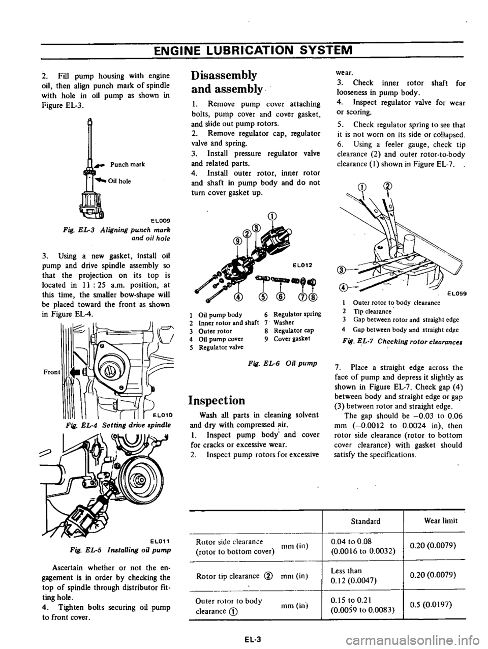
Fill
pump
housing
with
engine
oil
then
align
punch
mark
of
spindle
with
hole
in
oil
pump
as
shown
in
Figure
EL
3
Punch
mark
EL009
Fig
EL
3
Aligning
punch
mark
and
oil
hole
3
Using
a
new
gasket
install
oil
pump
and
drive
spindle
assembly
so
that
the
projection
on
its
top
is
located
in
II
25
a
m
position
at
this
time
the
smaller
bow
shape
will
be
placed
toward
the
front
as
shown
in
Figure
EL
4
JI
I
c
J
V
Front
J
@
9@
tr
i
d
L
It
I
I
EL010
Fig
EL
4
Setting
drive
pindle
o
EL011
Fig
EL
5
Imtalling
oil
pump
Ascertain
whether
or
not
the
en
gagement
is
in
order
by
checking
the
top
of
spindle
through
distributor
fit
ting
hole
4
Tighten
bolts
securing
oil
pump
to
front
cover
Disassembly
and
assembly
I
Remove
pump
cover
attaching
bolts
pump
cover
and
cover
gasket
and
slide
out
pump
rotors
2
Remove
regulator
cap
regulator
valve
and
spring
3
Install
pressure
regulator
valve
and
related
parts
4
Install
outer
rotor
inner
rotor
and
shaft
in
pump
body
and
do
not
turn
cover
gasket
up
CD
El012
r
@
@
CD@
1
Oil
pump
body
2
Inner
rotor
and
shaft
3
Outer
rotor
4
Oil
pump
cover
5
Regulator
valve
6
Regulator
spring
7
Washer
8
Regulator
cap
9
Cover
gasket
Fig
EL
6
Oil
pump
Inspection
Wash
all
parts
in
cleaning
solvent
and
dry
with
compressed
ir
I
Inspect
pump
body
and
cover
for
cracks
or
excessive
wear
2
Inspect
pump
rotors
for
excessive
Rotor
side
clearance
rotor
to
bottom
cover
Olm
in
Rotor
tip
clearance
@
mOl
in
Outer
rotor
to
body
clearance
D
mm
inl
EL
3
wear
3
Check
inner
rotor
shaft
for
looseness
in
pump
body
4
Inspect
regulator
valve
for
wear
or
scoring
5
Check
regulator
spring
to
see
that
it
is
not
worn
on
its
side
or
collapsed
6
Using
a
feeler
gauge
check
tip
clearance
2
and
outer
rotor
to
body
clearance
I
shown
in
Figure
EL
7
1
Outer
rotor
to
body
clearance
2
Tip
clearance
3
Gap
between
rotor
and
straight
edge
4
Gap
between
body
and
straight
edg
e
Fig
EL
7
Checking
rotor
clearance
7
Place
a
straight
edge
across
the
face
of
pump
and
depress
it
slightly
as
shown
in
Figure
EL
7
Check
gap
4
between
body
and
straight
edge
or
gap
3
between
rotor
and
straight
edge
The
gap
should
be
0
03
to
0
06
mm
0
0012
to
0
0024
in
then
rotor
side
clearance
rotor
to
bottom
cover
clearance
with
gasket
should
satisfy
the
specifications
Standard
Wear
limit
0
04
to
0
08
0
0016
to
0
0032
0
20
0
0079
Less
than
0
12
0
0047
0
20
0
0079
0
15
to
0
21
0
0059
to
0
0083
0
5
0
0197
Page 87 of 537
ENGINE
LUBRI
CATION
SYSTEM
Note
Pump
rotors
and
body
are
not
serviced
separately
If
pump
rotors
or
body
are
damaged
or
worn
replacement
of
the
entire
oil
pump
assembly
is
necessary
Tightening
torque
Oil
pump
mounting
bolts
Oil
pump
cover
bolts
Regulator
valve
cap
nut
Specifications
Oil
pressure
at
idling
Regulator
valve
spring
Free
length
Pressured
length
Regulator
valve
opening
pressure
OIL
FILTER
The
oil
filter
is
a
cartridge
type
The
oil
filter
element
should
be
reo
placed
periodically
with
the
use
of
Oil
Filter
Wrench
ST19320000
When
installing
an
oil
filter
fasten
it
to
cylinder
block
by
hand
Note
Do
not
overtighten
filter
or
oil
leakage
may
occur
OIL
PRESSURE
REGULATOR
VALVE
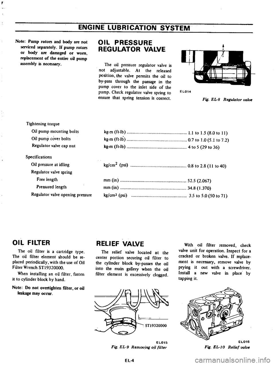
The
oil
pressure
regulator
valve
is
not
adjustable
At
the
released
position
the
valve
permits
the
oil
to
by
pass
through
the
passage
in
the
pump
cover
to
the
inlet
side
of
the
pump
Check
regulator
valve
spring
to
ensure
that
spring
tension
is
correct
kg
m
ft
Ib
kg
m
ft
lb
kg
m
ft
lb
kg
cm2
psi
mm
in
mm
in
kg
em
2
psi
RELIEF
VALVE
The
relief
valve
located
at
the
center
portion
securing
oil
fIlter
to
the
cylinder
block
by
passes
the
oil
into
the
main
gallery
when
the
oil
fIlter
element
is
excessively
clogged
STl9320000
EL015
Fig
EL
9
Removing
oil
filter
EL
4
EL014
Fig
EL
B
Regulator
value
l
l
to
1
5
8
0
to
11
0
7
to
1
0
5
Ito
7
2
4
to
5
29
to
36
0
8
to
2
8
II
to
40
52
5
2
067
34
8
1
370
35
to
5
0
50
to
71
With
oil
fIlter
removed
check
valve
unit
for
operation
Inspect
for
a
cracked
or
broken
valve
If
replace
ment
is
necessary
remove
valve
by
prying
it
out
with
a
screwdriver
Install
a
new
valve
in
place
by
tapping
it
EL016
Fig
EL
JO
Relief
lJOlue