radiator DATSUN PICK-UP 1977 User Guide
[x] Cancel search | Manufacturer: DATSUN, Model Year: 1977, Model line: PICK-UP, Model: DATSUN PICK-UP 1977Pages: 537, PDF Size: 35.48 MB
Page 96 of 537
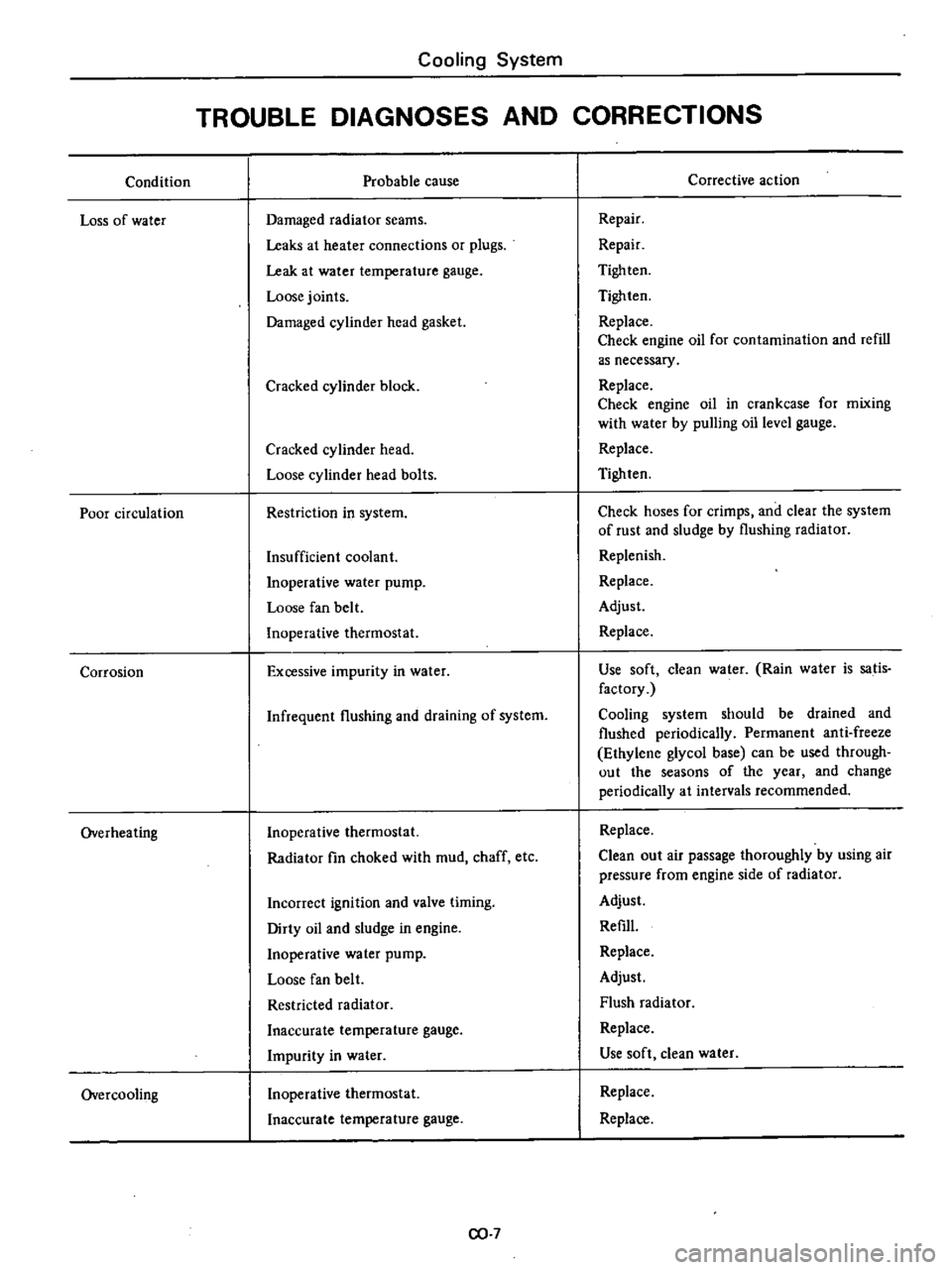
Condition
Loss
of
water
Poor
circulation
Corrosion
Overheating
Overcooling
Cooling
System
TROUBLE
DIAGNOSES
AND
CORRECTIONS
Probable
cause
Damaged
radiator
seams
Leaks
at
heater
connections
or
plugs
Leak
at
water
temperature
gauge
Loose
joints
Damaged
cylinder
head
gasket
Cracked
cylinder
block
Cracked
cylinder
head
Loose
cylinder
head
bolts
Restriction
in
system
Insufficient
coolant
Inoperative
water
pump
Loose
fan
belt
Inoperative
thermostat
Excessive
impurity
in
water
Infrequent
flushing
and
draining
of
system
Inoperative
thermostat
Radiator
fin
choked
with
mud
chaff
etc
Incorrect
ignition
and
valve
timing
Dirty
oil
and
sludge
in
engine
Inoperative
water
pump
Loose
fan
belt
Restricted
radiator
Inaccurate
temperature
gauge
Impurity
in
water
Inoperative
thermostat
Inaccurate
temperature
gauge
CO
7
Corrective
action
Repair
Repair
Tigh
ten
Tighten
Replace
Check
engine
oil
for
contamination
and
refill
as
necessary
Replace
Check
engine
oil
in
crankcase
for
mixing
with
water
by
pulling
oil
level
gauge
Replace
Tighten
Check
hoses
for
crimps
and
clear
the
system
of
rust
and
sludge
by
flushing
radiator
Replenish
Replace
Adjust
Replace
Use
soft
clean
water
Rain
water
is
satis
factory
Cooling
system
should
be
drained
and
flushed
periodically
Permanent
anti
freeze
Ethylene
glycol
base
can
be
used
through
out
the
seasons
of
the
year
and
change
periodically
at
intervals
recommended
Replace
Clean
out
air
passage
thoroughly
by
using
air
pressure
from
engine
side
of
radiator
Adjust
Refill
Replace
Adjust
Flush
radiator
Replace
Use
soft
clean
water
Replace
Replace
Page 101 of 537

TEMPERATURE
SENSOR
The
temperature
sensor
is
attached
to
the
inside
of
the
air
cleaner
The
bimetal
built
in
the
sensor
detects
the
under
hood
air
temperature
and
opens
or
closes
the
vacuum
passage
in
the
sensor
The
construction
of
the
tempera
ture
sensor
is
shown
in
the
following
CD
V
00
@
I
I
@
j
I
I
1
Protector
cover
Screw
Adjusting
frame
Air
temperature
bi
metal
Rivet
Valve
seat
frame
Lower
frame
Air
bleed
valve
Gasket
Fig
EF
6
Temperature
senior
EF206
VACUUM
MOTOR
AND
AIR
CONTROL
VALVE
The
vacuum
pressure
which
varies
with
opening
of
the
carburetor
throt
tle
acts
upon
the
vacuum
motor
dia
phragm
The
valve
shaft
attached
to
the
diaphragm
is
then
moved
up
or
down
in
response
to
the
vacuum
on
the
diaphragm
This
movement
of
the
valve
shaft
actuates
the
air
control
valve
to
control
the
temperature
of
the
air
to
be
introduced
into
the
air
cleaner
pr
to
I
1
Valve
spring
00
2
Diaphragm
@
3
Retainer
E
F
207
4
Valve
shaft
Fig
EF
7
Vacuum
motor
REMOVAL
AND
INSTALLATION
TEMPERATURE
SENSOR
Removal
Using
pliers
flatten
clip
con
Engine
Fuel
neeting
vacuum
hose
to
sensor
vacuum
tube
I
Pipe
2
Calch
3
Fixed
with
adhesive
4
Hose
5
Tab
6
Clip
7
Gasket
EC019
Fig
EF
B
Removal
of
semor
2
Disconnect
hose
from
sensor
3
Take
off
clip
from
sensor
vacuum
tube
and
dismount
sensor
body
from
air
cleaner
Note
The
gasket
between
sensor
and
air
cleaner
is
bonded
to
the
air
cleaner
side
and
should
not
be
removed
Inatallatlon
Mount
sensor
on
the
specified
position
For
mounting
position
of
sensor
see
the
following
EF717
Fig
EF
9
lalling
se
or
2
Insert
clip
into
vacuum
tube
of
sensor
After
installing
each
vacuum
hose
secure
hose
with
the
clip
Note
Be
sure
to
install
vacuum
hose
correctly
Correct
position
is
R
H
side
to
Nissan
mark
at
the
top
face
of
sensor
for
intake
manifold
L
H
side
for
vacuum
motor
VACUUM
MOTOR
1
Remove
screws
securing
vacuum
motor
to
air
cleaner
2
Disconnect
valve
shaft
attached
to
vacuum
motor
diapluagm
from
air
control
valve
and
remove
cacuum
motor
assembly
from
air
cleaner
3
To
install
reverse
the
removal
procedure
FRESH
AIR
DUCT
I
Disconnect
fresh
air
duct
at
air
cleaner
2
Fresh
air
duct
is
provided
with
projections
on
its
air
inlet
side
end
Hold
fresh
air
duct
with
a
hand
and
carefully
pull
out
from
radiator
core
support
while
turning
it
in
either
direction
3
To
install
reverse
the
removal
procedure
Be
sure
to
insert
projec
lions
of
fresh
air
duct
securely
into
mounting
hole
in
radiator
core
sup
port
EF518
EF
5
Fresh
air
duct
Air
cleaner
Duct
mounting
hole
Radiator
Radiator
core
support
Fig
EF
I0
Removal
of
fresh
air
duct
Page 219 of 537
Engine
Removal
Installation
ENGINE
REMOVAL
AND
INSTAllATION
REMOVAL
INSTALLATION
ENGINE
MOUNTING
INSULATORS
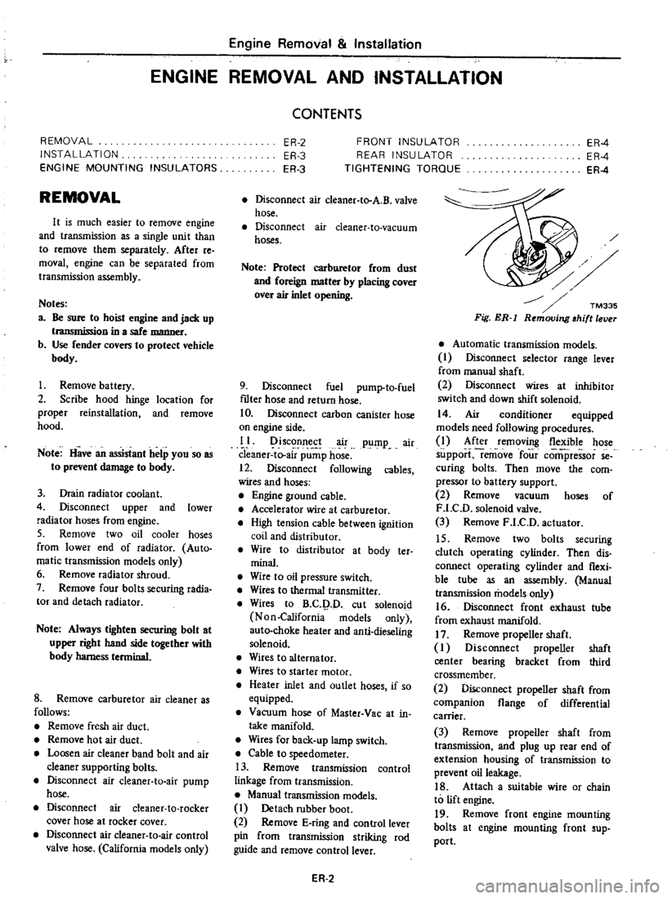
REMOVAL
It
is
much
easier
to
remove
engine
and
transmission
as
a
single
unit
than
to
remove
them
separately
After
re
moval
engine
can
be
separated
from
transntission
assembly
Notes
a
Be
sure
to
hoist
engine
and
jack
up
transmission
in
a
safe
manner
b
Use
fender
cove
to
protect
vehicle
body
1
Remove
battery
2
Scribe
hood
hinge
location
for
proper
reinstallation
and
remove
hood
Note
Have
an
assistant
help
you
so
as
to
prevent
damage
to
body
3
Drain
radiator
coolant
4
Disconnect
upper
and
lower
radiator
hoses
from
engine
5
Remove
two
oil
cooler
hoses
from
lower
end
of
radiator
Auto
ma
tic
transmission
models
only
6
Remove
radiator
shroud
7
Remove
four
bolts
securing
radia
tor
and
detach
radiator
Note
Always
tighten
securing
bolt
at
upper
right
hand
side
together
with
body
harness
terminal
8
Remove
carburetor
air
cleaner
as
follows
Remove
fresh
air
duct
Remove
hot
air
duct
Loosen
air
cleaner
band
bolt
and
air
cleaner
supporting
bolts
Disconnect
air
cleaner
ta
air
pump
hose
Disconnect
air
cleaner
to
rocker
cover
hose
at
rocker
cover
Disconnect
air
cleaner
to
air
control
valve
hose
California
models
only
CONTENTS
ER
2
ER
3
ER
3
FRONT
INSULATOR
REAR
INSULATOR
TIGHTENING
TORQUE
ER
4
ER
4
ER
4
Disconnect
air
deaner
to
A
B
valve
hose
Disconnect
air
cleaner
ta
vacuum
hoses
Note
Protect
carburetor
from
dust
and
foreign
matter
by
placing
cover
over
air
inlet
opening
9
Disconnect
fuel
pump
to
fuel
fdter
hose
and
return
hose
10
Disconnect
carbon
canister
hose
on
engine
side
II
Disconnect
air
pump
air
C1eaner
to
al
p
p
hose
12
Disconnect
following
cables
wires
and
hoses
Engine
ground
cable
Accelerator
wire
at
carburetor
High
tension
cable
between
ignition
coil
and
distributor
Wire
to
distributor
at
body
ter
minal
Wire
to
oil
pressure
switch
Wires
to
thermal
transmitter
Wires
to
B
C
p
D
cut
solenoid
Non
California
models
only
auto
choke
heater
and
anti
dieseling
solenoid
Wires
to
alternator
Wires
to
starter
motor
Heater
inlet
and
outlet
hoses
if
so
equipped
Vacuum
hose
of
Master
Vac
at
in
taJce
manifold
Wires
for
back
up
lamp
switch
Cable
to
speedometer
13
Remove
transmission
control
linkage
from
transmission
Manual
transmission
models
I
Detach
rubber
boot
2
Remove
E
ring
and
control
lever
pin
from
transmission
striking
rod
guide
and
remove
control
lever
ER
2
Fig
ER
l
Automatic
transmission
models
I
Disconnect
selector
range
lever
from
manual
shaft
2
Disconnect
wires
at
inhibitor
switch
and
down
shift
solenoid
14
Air
conditioner
equipped
models
need
following
procedures
1
After
removing
flexible
hose
support
remove
four
comi
ressor
se
curing
bolts
Then
move
the
com
pressor
to
battery
support
2
Remove
vacuum
hoses
of
F
LC
D
solenoid
valve
3
Remove
F
LC
D
actuator
15
Remove
two
bolts
securing
clutch
operating
cylinder
Then
dis
connect
operating
cylinder
and
flexi
ble
tube
as
an
assembly
Manual
transmission
models
only
16
Disconnect
front
exhaust
tube
from
exhaust
manifold
17
Remove
propeller
shaft
I
Disconnect
propeller
shaft
center
bearing
bracket
from
third
crossmember
2
Disconnect
propeller
shaft
from
companion
flange
of
differential
carrier
3
Remove
propeller
shaft
from
transmission
and
plug
up
rear
end
of
extension
housing
of
transmission
to
prevent
oil
leakage
18
Attach
a
suitable
wire
or
chain
to
lift
engine
19
Remove
front
engine
mounting
bolts
at
engine
mounting
front
sup
port
Page 323 of 537
Automatic
Transmission
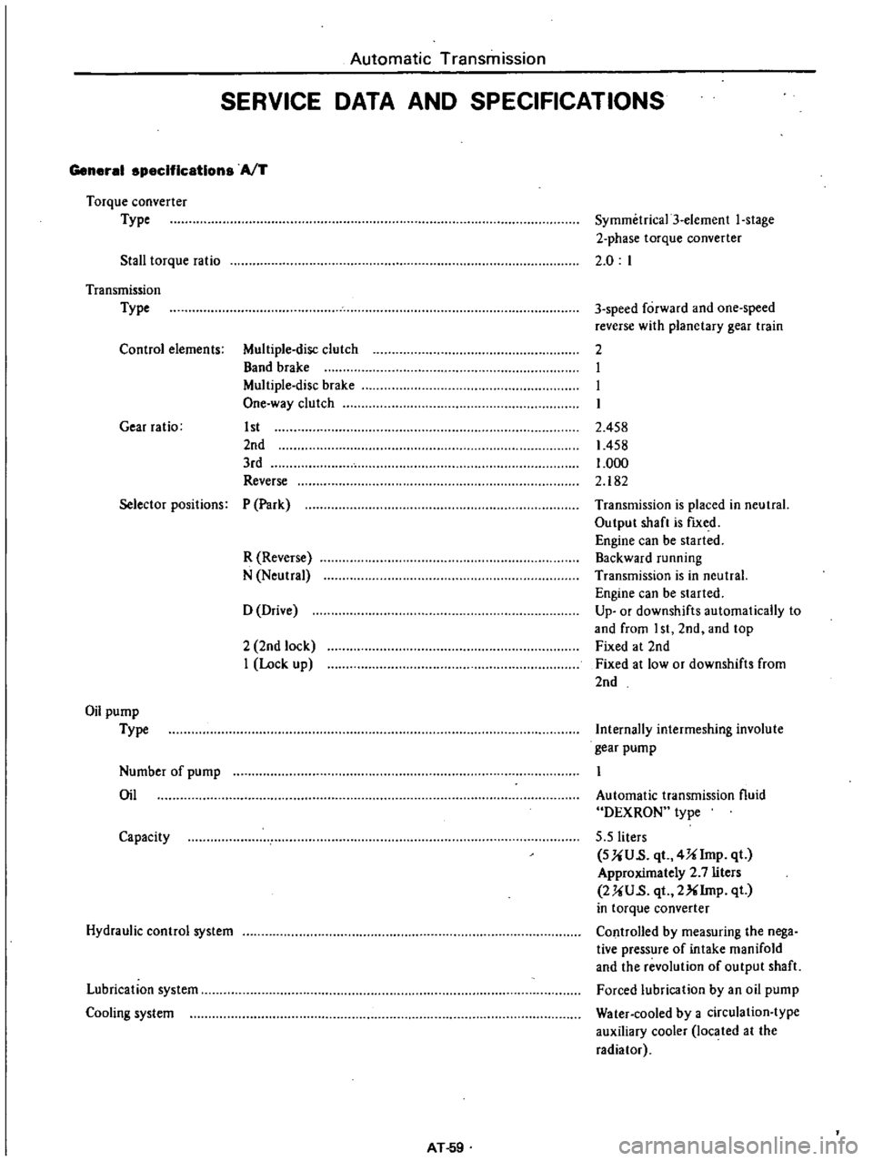
SERVICE
DATA
AND
SPECIFICATIONS
General
specifications
AfT
Torque
converter
Type
Stall
torque
ratio
Symmetrica13
element
I
stage
2
phase
torque
converter
2
0
I
Transmission
Type
Control
elements
Multiple
disc
clutch
Band
brake
Multiple
disc
brake
One
way
clutch
Gear
ratio
1st
2nd
3rd
Reverse
3
speed
forward
and
one
speed
reverse
with
planetary
gear
train
2
I
I
I
2
458
1458
1
000
2
182
Selector
positions
P
Park
R
Reverse
N
Neutral
Transmission
is
placed
in
neutral
Output
shaft
is
fIXed
Engine
can
be
started
Backward
running
Transmission
is
in
neutral
Engine
can
be
started
Up
or
downshifts
automatically
to
and
from
I
st
2nd
and
top
Fixed
at
2nd
Fixed
at
low
or
downshifts
from
2nd
o
Drive
2
2nd
lock
I
Lock
up
Oil
pump
Type
Internally
intermeshing
involute
gear
pump
Number
of
pump
Oil
Automatic
transmission
fluid
DEXRON
type
5
5
liters
SUU
s
qt
4Ulmp
qt
Approximately
2
7
liters
2UU
s
qt
2XIrnp
qt
in
torque
converter
Controlled
by
measuring
the
nega
tive
pressure
of
intake
manifold
and
the
revolution
of
output
shaft
Forced
lubrication
by
an
oil
pump
Water
cooled
by
a
circulation
type
auxiliary
cooler
located
at
the
radiator
Capacity
Hydraulic
control
system
Lubrication
system
Cooling
system
AT
59
Page 360 of 537

Note
When
installing
fulcrum
pin
insert
it
from
rearward
of
vehicle
12
Install
tension
rod
shock
ab
sorber
I
stabilizer
torsion
bar
spring
and
knuckle
arm
referring
to
the
related
paragraphs
13
Install
brake
disc
to
knuckle
spindle
and
torque
securing
bolt
to
4
2
to
5
0
kg
m
30
to
36
ft
Ib
14
Install
wheel
and
brake
drum
as
an
assembly
and
torque
knuckle
spin
dle
nut
to
8
0
to
9
0
kg
m
58
to
65
ft
Ib
DISASSEMBLY
AND
ASSEMBLY
Upper
link
I
Detach
upper
link
spindle
from
upper
links
and
remove
clamp
dust
cover
and
dust
seal
Secure
upper
link
in
a
vise
and
loosen
screw
bushing
Assemble
link
spindle
in
reverse
sequence
to
disassembling
noting
the
following
instructions
2
Torque
screw
bushing
on
upper
link
to
3S
to
55
kg
m
253
to
398
ft
Ib
Install
new
dust
seal
and
dust
cover
and
secure
them
with
clamp
3
Coat
grease
to
screw
bushing
in
side
and
the
thread
portion
of
upper
link
spindle
liberally
Screw
front
and
rear
links
to
upper
link
spindle
in
the
same
length
so
as
to
obtain
the
speci
fied
figures
as
shown
in
Figure
FA
23
Unit
mm
in
I
44
6
1
156
FA2
Upper
link
and
upper
link
spindle
Fig
FA
23
Front
Axle
Front
Suspension
4
Make
sure
to
operate
upper
link
spindle
smoothly
after
installation
5
Replace
filler
plug
with
grease
nipple
and
pack
grease
until
grease
comes
out
from
dust
cover
Reinstall
f1ller
plug
Lower
link
When
installing
torque
arm
on
lower
link
tighten
it
to
the
following
specifications
Serration
boss
1
8
to
2
6
kg
m
13
to
19
ft
Ib
Arm
head
2
7
to
3
7
kg
m
20
to
27
ft
tb
INSPECTION
Upper
link
spindle
fulcrum
pin
and
screw
bushing
Apply
screw
bushing
to
upper
link
spindle
or
fulcrum
pin
and
measure
axial
end
play
between
them
When
the
end
play
exceeds
0
35
mm
0
0138
in
replace
upper
link
spindle
or
fulcrum
pin
together
with
screw
bushings
Condition
Vehicle
empty
no
payload
Vehicle
loaded
Notes
a
Vehicle
empty
no
payload
consists
of
the
following
conditions
I
Full
tank
of
gasoline
radiator
f1lled
and
engine
oil
level
full
2
Spare
tire
wheel
jack
and
jack
handle
in
design
position
b
Vehicle
loaded
consists
of
the
fol
lowing
conditions
For
all
models
2
persons
and
SIlO
leg
I
103lb
payload
FA
Check
the
screw
of
upper
link
spindle
fulcrum
pin
and
screw
bush
ing
and
repair
or
replace
if
necessary
Note
Discard
dust
cover
and
dust
seal
when
disassembled
ADJUSTMENT
VEHICLE
POSTURE
Vehicle
posture
may
be
incorrect
due
to
weakened
spring
or
other
faulty
condition
The
following
procedures
are
necessary
when
adjustment
is
Ie
quired
That
is
the
vehicle
posture
can
be
adjusted
by
obtaining
only
the
speci
fied
H
dimension
changing
the
length
of
anchor
bolt
I
Raise
front
of
vehicle
on
stands
2
Adjust
H
dimension
with
turn
ing
nut
adjusting
anchor
bolt
H
dimension
changes
approximately
3
5
mm
0
J38
in
vertically
when
adjust
nut
is
turned
one
complete
turn
3
To
make
the
best
vehicle
posture
H
dimension
must
be
in
the
follow
ing
range
H
dimension
mOl
in
All
models
79
to
84
3
11
to
3
31
54
5
2
15
o
i
Fig
FA
24
FA242
Dimension
for
standard
vehicle
postl4re
Page 428 of 537
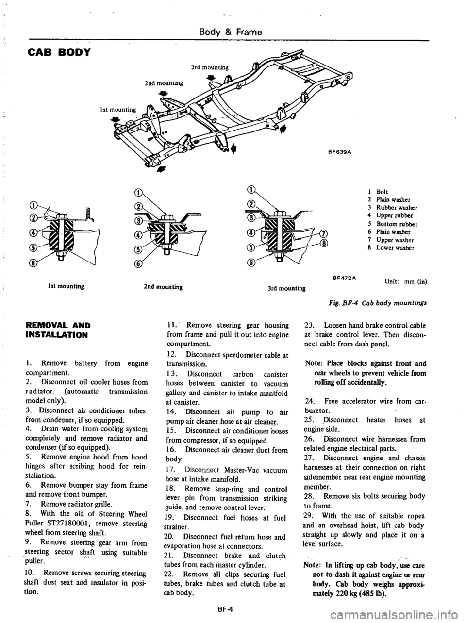
CAB
BODY
Body
Frame
Ist
mounting
2nd
mounting
1
Bolt
2
Plain
washer
3
Rubber
washer
4
Upper
rubber
5
Bottom
rubber
6
Plain
w
er
7
Upper
washer
8
Lower
washer
1st
mounting
REMOVAL
AND
INSTALLATION
Remove
battery
from
engine
compartment
2
Disconnect
oil
cooler
hoses
from
radiator
automatic
transmission
model
only
3
Disconnect
air
conditioner
tubes
from
condenser
if
so
equipped
4
Drain
water
from
cooling
system
completely
and
remove
radiator
and
condenser
if
so
equipped
5
Remove
engine
hood
from
hood
hinges
after
scribing
hood
for
rein
stallation
6
Remove
bumper
stay
from
frame
and
remove
front
bumper
7
Remove
radiator
grille
8
With
the
aid
of
Steering
Wheel
Puller
ST27
180001
remove
steering
wheel
from
steering
shaft
9
Remove
steering
gear
arm
from
steering
sector
shaft
using
suitable
puller
10
Remove
screws
securing
steering
shaft
dust
seat
and
insulator
in
posi
tion
2nd
mounting
3rd
mounting
II
Remove
steering
gear
housing
from
frame
and
pull
it
out
into
engine
compartment
12
Disconnect
speedometer
cable
at
transmission
1
3
Disconnect
carbon
canister
hoses
between
canister
to
vacuum
gallery
and
canister
to
intake
manifold
at
canister
14
Disconnect
air
pump
to
air
pump
air
cleaner
hose
at
air
cleaner
15
Disconnect
air
conditioner
hoses
from
compressor
if
so
equipped
16
Disconnect
air
cleaner
duct
from
body
17
Disconnect
Master
Vac
vacuum
hose
at
intake
manifold
18
Remove
snap
ring
and
control
lever
pin
from
transmission
striking
guide
and
remove
control
lever
19
Disconnect
fuel
hoses
at
fuel
strainer
20
Disconnect
fuel
return
hose
and
evaporation
hose
at
connectors
21
Disconnect
brake
and
clutch
tubes
from
each
master
cylinder
22
Remove
all
clips
securing
fuel
tubes
brake
tubes
and
clutch
tube
at
cab
body
BF
4
BF472A
Unit
mm
in
Fig
BF
4
Cab
body
mountings
23
Loosen
hand
brake
control
cable
at
brake
control
lever
Then
discon
nect
cable
from
dash
panel
Note
Place
blocks
against
front
and
rear
wheels
to
prevent
vehicle
from
rolling
off
accidentally
24
Free
accelerator
wire
from
car
buretor
25
Disconnect
heater
hoses
at
engine
side
26
Disconnect
wire
harnesses
from
related
engine
electrical
parts
27
Disconnect
engine
and
chassis
harnesses
at
their
connection
on
right
sidemember
near
rear
engine
mounting
member
28
Remove
six
bolts
securing
body
to
frame
29
With
the
use
of
suitable
ropes
and
an
overhead
hoist
lift
cab
body
straight
up
slowly
and
place
it
on
a
level
surface
Note
In
lifting
up
cab
body
use
care
not
to
dash
it
against
engine
or
rear
body
Cab
body
weighs
approxi
mately
220
kg
485
Ib
Page 431 of 537
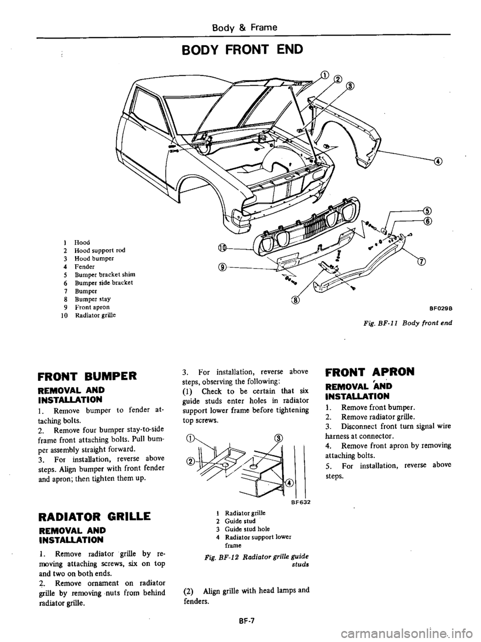
Body
Frame
BODY
FRONT
END
1
Hood
2
Hood
support
rod
@
3
Hood
bumper
4
Fender
@
5
Bumper
bracket
shim
6
Bumper
side
bracket
7
Bumper
8
Bumper
stay
9
Front
apron
10
Radiator
grille
FRONT
BUMPER
REMOVAL
AND
INSTALLATION
L
Remove
bumper
to
fender
at
taching
bolts
2
Remove
four
bumper
stay
to
side
frame
front
attaching
bolts
Pull
bum
per
assembly
straight
forward
3
For
installation
reverse
above
steps
Align
bumper
with
front
fender
and
apron
then
tighten
them
up
RADIATOR
GRILLE
REMOVAL
AND
INSTAUATION
I
Remove
radiator
grille
by
re
moving
attaching
screws
six
on
top
and
two
on
both
ends
Remove
ornament
on
radiator
grille
by
removing
nuts
from
behind
radiator
grille
4
ZID
@
7
BF029B
Fig
BF
11
Body
front
end
FRONT
APRON
3
For
installation
reverse
above
steps
observing
the
following
I
Check
to
be
certain
that
six
guide
studs
enter
holes
in
radiator
support
lower
frame
before
tightening
top
screws
CD
@
REMOVAL
AND
INSTALLATION
I
Remove
front
bumper
2
Remove
radiator
grille
3
Disconnect
front
turn
signal
wire
harness
a
t
connector
4
Remove
front
apron
by
removing
attaching
bolts
S
For
installation
reverse
above
steps
B
632
1
Radiator
grille
2
Guide
stud
3
Guide
stud
hole
4
Radiator
support
lower
frame
Fig
BF
12
Radiator
grille
guide
studs
2
Align
grille
with
head
lamps
and
fenders
BF
7
Page 432 of 537
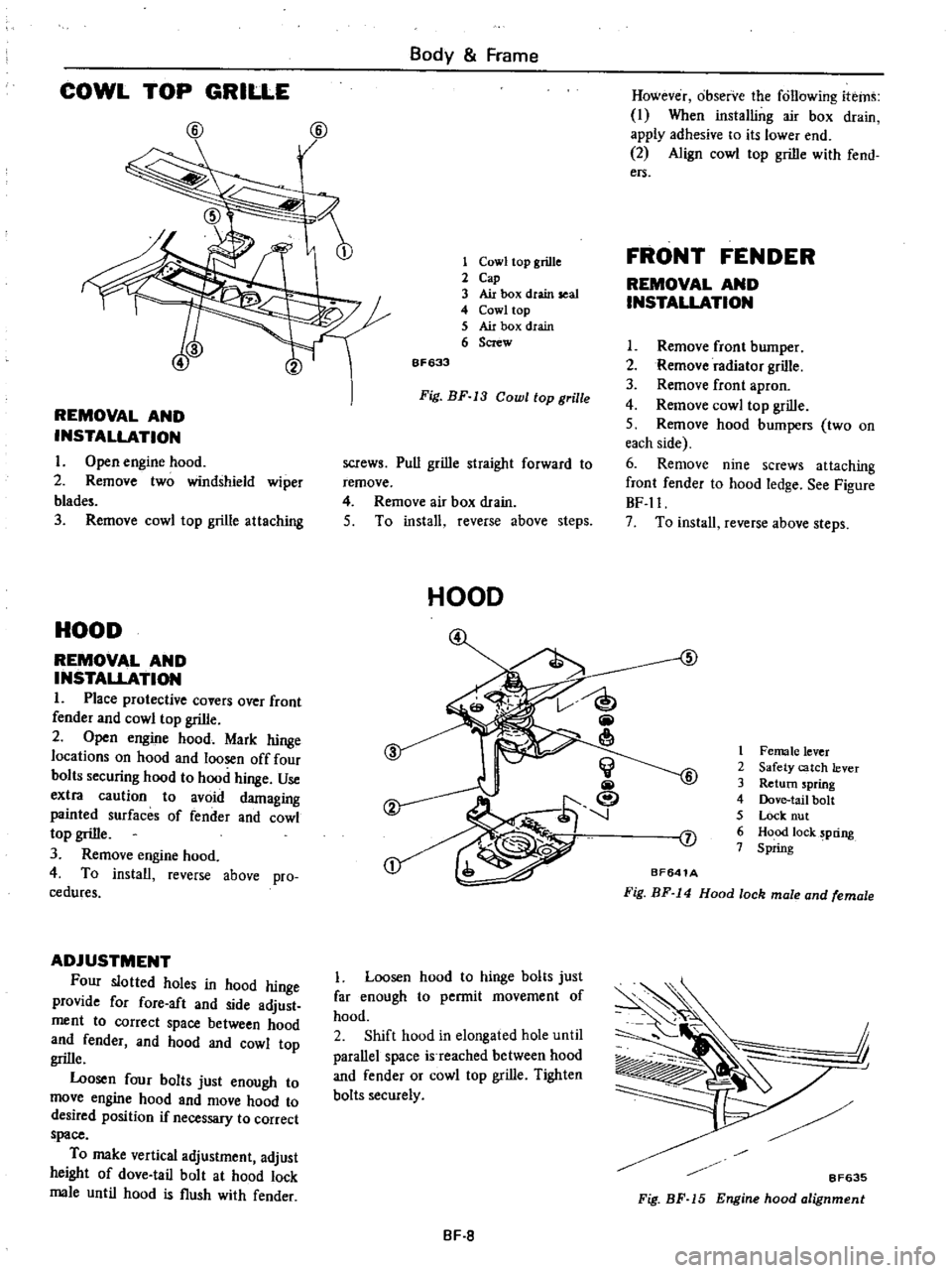
COWL
TOP
GRILLE
@
@
REMOVAL
AND
INSTALLATION
I
Open
engine
hood
2
Remove
two
windshield
wiper
blad
3
Remove
cowl
top
grille
attaching
HOOD
REMOVAL
AND
INSTALLATION
1
Place
protective
covers
over
front
fender
and
cowl
top
grille
2
Open
engine
hood
Mark
hinge
locations
on
hood
and
loosen
off
four
bolts
securing
hood
to
hood
hinge
Use
extra
caution
to
avoid
damaging
painted
surfaces
of
fender
and
cowl
top
grille
3
Remove
engine
hood
4
To
install
reverse
above
pro
cedures
ADJUSTMENT
Four
slotted
holes
in
hood
hinge
provide
for
fore
aft
and
side
adjust
ment
to
correct
space
between
hood
and
fender
and
hood
and
cowl
top
grille
Loosen
four
bolts
just
enough
to
move
engine
hood
and
move
hood
to
desired
position
if
necessary
to
correct
space
To
make
vertical
adjustment
adjust
height
of
dove
tail
bolt
at
hood
lock
male
until
hood
is
flush
with
fender
Body
Frame
1
Cowl
top
grille
2
Cap
3
Air
box
dtain
seal
4
Cowl
top
5
Air
box
drain
6
Screw
6F633
Fig
BF
13
Cowl
top
grille
screws
Pull
grille
straight
forward
to
remove
4
Remove
air
box
drain
5
To
install
reverse
above
steps
HOOD
Loosen
hood
to
hinge
bolts
just
far
enough
to
permit
movement
of
hood
2
Shift
hood
in
elongated
hole
until
parallel
space
is
reached
between
hood
and
fender
or
cowl
top
grille
Tighten
bolts
securely
BF
8
However
observe
the
following
items
I
When
installing
air
box
drain
apply
adhesive
to
its
lower
end
2
Align
cowl
top
grille
with
fend
ers
FRONT
FENDER
REMOVAL
AND
INSTALLATION
I
Remove
front
bumper
2
Remove
radiator
grille
3
Remove
front
apron
4
Remove
cowl
top
grille
S
Remove
hood
bumpers
two
on
each
side
6
Remove
nine
screws
attaching
front
fender
to
hood
ledge
See
Figure
BF
ll
7
To
install
reverse
above
steps
5
1
Female
lever
2
Safety
catch
lever
3
Return
spring
4
Dove
tail
bolt
S
Lock
nut
6
Hood
lock
pring
7
Spring
J
BF641A
Fig
BF
14
Hood
lock
male
and
female
j
I
8F635
Fig
BF
15
Engine
hood
alignment
Page 434 of 537
REMOVAL
AND
INSTALLATION
I
Remove
hood
lock
male
by
re
moving
two
attaching
bolts
2
To
remove
hood
lock
female
first
remove
radiator
grille
Back
off
two
bolts
securing
hood
lock
female
in
position
Hood
lock
female
can
now
be
taken
out
3
Remove
two
bolts
attaching
hood
lock
handle
assembly
to
dash
side
paneL
Disconnect
cable
at
hood
lock
female
and
remove
cable
clamps
Pull
cable
out
into
cab
4
To
install
hood
lock
male
and
female
reverse
removal
procedure
Mter
installation
check
to
insure
that
they
are
properly
aligned
5
To
install
hood
lock
handle
as
sembly
reverse
steps
observing
the
following
notes
I
Check
to
be
certain
that
cable
clamps
are
tight
and
secure
2
Install
hood
lock
handle
bracket
in
place
by
using
two
of
four
holes
See
Figure
BF
19
Body
Frame
@
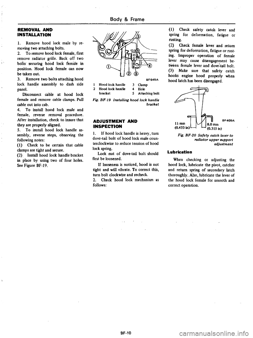
1
Hood
tock
handle
2
Hood
lock
handle
bracket
BF645A
3
Clamp
4
Hole
5
Attaching
bolt
Fig
BF
19
1MtalIing
hood
lock
handle
brocket
ADJUSTMENT
AND
INSPECTION
I
If
hood
lock
handle
is
heavy
turn
dove
tail
bolt
of
hood
lock
male
coun
terclockwise
to
reduce
tension
of
hood
lock
spring
Lock
nut
of
dove
tail
bolt
should
fust
be
loosened
If
looseness
is
noticed
hood
is
not
tight
and
will
vibrate
To
correct
this
turn
bolt
clockwise
and
recheck
2
Check
hood
lock
mechanism
as
follows
BF
10
I
Check
safety
catch
lever
and
spring
for
deformation
fatigue
or
rusting
2
Check
female
lever
and
return
spring
for
deformation
fatigue
or
rust
ing
Improper
operation
of
female
lever
may
cause
disengagement
be
tween
female
lever
and
dove
tail
bolt
3
Make
sure
that
safety
catch
hooks
engine
hood
properly
when
hood
latch
has
been
disengaged
0l
11
mm
I
nun
BF409A
0
433
in
0
3t5
in
Fig
BF
20
Safety
catch
lever
to
radiator
upper
support
acVu5tment
Lubrication
When
checking
or
adjusting
the
hood
lock
lubricate
the
pivot
catcher
and
return
spring
of
secondary
latch
thoroughly
Also
lubricate
the
lever
of
the
hood
lock
female
for
smooth
and
correct
operation
Page 450 of 537
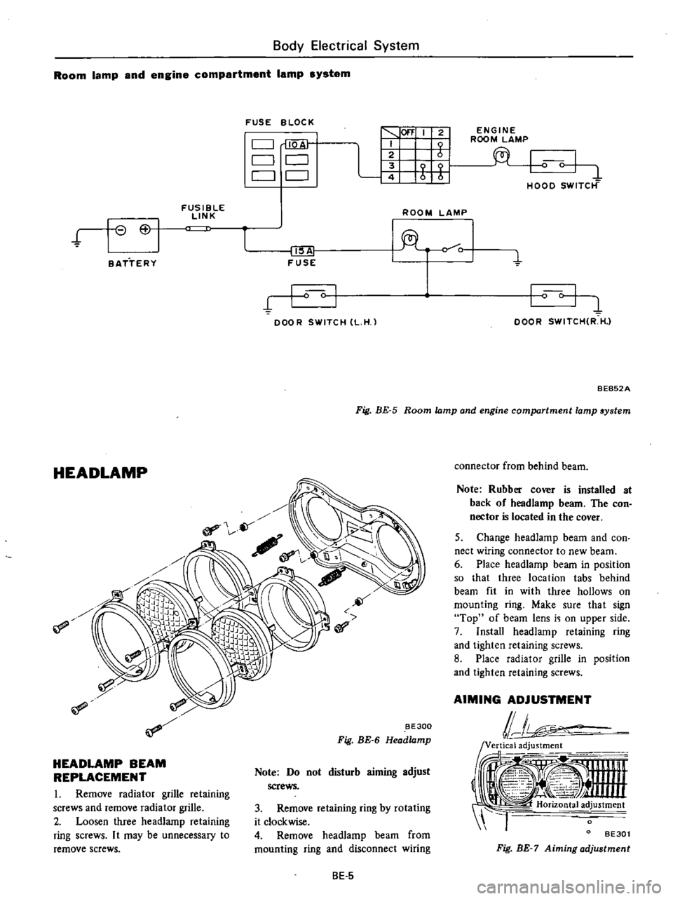
Body
Electrical
System
Room
lamp
and
engine
compartment
lamp
system
FUSE
BLOC
K
C
J
QA
C
J
CJ
CJ
CJ
1
100
I
2
I
I
t1
Wf
t
fi
FUSIBLE
LINK
ROOM
LAMP
t
I
6
I
II
lA
FUSE
o
C
1
BATTERY
I
I
DOOR
SWITCH
L
H
l
ENGINE
ROOM
LAMP
I
0
I
1
HOOD
SWITCt
f
I
c
I
DOOR
SWITCHIR
H
l
Fig
BE
5
Room
lamp
and
engine
compartment
lamp
system
BE852A
HEADLAMP
if
BE300
Fig
BE
6
Head
amp
HEADLAMP
BEAM
REPLACEMENT
I
Remove
radiator
grille
retaining
screws
and
remove
radiator
grille
2
Loosen
three
headlamp
retaining
ring
screws
I
t
may
be
unnecessary
to
remove
screws
Note
Do
not
disturb
aiming
adjust
screws
3
Remove
retaining
ring
by
rotating
it
clockwise
4
Remove
headlamp
beam
from
mounting
ring
and
disconnect
wiring
8E
5
connector
from
behind
beam
Note
Rubber
cover
is
installed
at
back
of
headlamp
beam
The
con
nector
is
located
in
the
cover
5
Change
headlamp
beam
and
con
nect
wiring
connector
to
new
beam
6
Place
headlamp
beam
in
position
so
that
three
location
tabs
behind
beam
fit
in
with
three
hollows
on
mounting
ring
Make
sure
that
sign
Top
of
beam
lens
i
i
on
upper
side
7
Install
headlamp
retaining
ring
and
tighten
retaining
screws
8
Place
radIator
grille
in
position
and
tighten
retaining
screws
AIMING
ADJUSTMENT
lJ
ii
i
tooi
1
Ji
Y
4
nnn
4
I
Horiz
tal
ad
justment
l
BE30l
Fig
BE
7
Aiming
adjustment