wheel DATSUN PICK-UP 1977 User Guide
[x] Cancel search | Manufacturer: DATSUN, Model Year: 1977, Model line: PICK-UP, Model: DATSUN PICK-UP 1977Pages: 537, PDF Size: 35.48 MB
Page 68 of 537
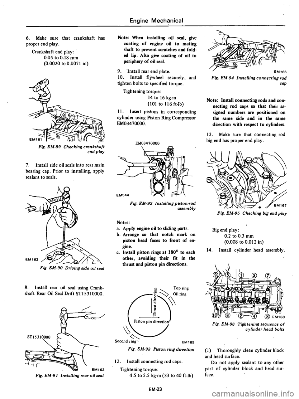
6
Make
sure
that
crankshaft
has
proper
end
play
Crankshaft
end
play
0
05
to
0
18
mm
0
0020
to
0
0071
in
Fig
EM
89
Checking
crankshaft
end
play
7
Install
side
oil
seals
into
rear
main
bearing
cap
Prior
to
installing
apply
sealant
to
seals
Fig
EM
90
Driving
side
oil
seal
8
Install
rear
oil
seal
using
Crank
shaft
Rear
Oil
Seal
Drift
STI5310000
r
STl5310000
r
EM163
Fig
EM
91
Installing
rear
oi
seal
Engine
Mechanical
Note
When
installing
oil
seal
give
coating
of
engine
oil
to
mating
shaft
to
prevent
scratches
and
fold
ed
lip
Also
give
coating
of
oil
to
periphery
of
oil
seal
9
Install
rear
end
plate
10
Install
flywheel
securely
and
tighten
bolts
to
specified
torque
Tightening
torque
14
to
16
kg
m
101
to
116
ft
lb
I
I
Insert
pistons
in
corresponding
cylinder
using
Piston
Ring
Compressor
EM03470000
EM03410000
I
EM544
Fig
EM
92
Installing
pi8ton
rod
a
Sembly
Notes
a
Apply
engine
oil
to
sliding
parts
b
Arrange
80
that
notch
mark
on
piston
head
faces
to
front
of
en
gine
c
Install
piston
rings
at
1800
to
each
other
avoiding
their
fit
in
the
thrust
and
piston
pin
directions
6
Top
ring
I
iilring
Piston
pin
ireClioJ
EM165
Fig
EM
93
PUtan
ring
direction
12
Install
connecting
rod
caps
Tightening
torque
4
5
to
5
5
kg
m
33
to
40
ft
lb
EM
23
Fig
EM
94
Installing
connecting
rod
cap
Note
Install
connecting
rods
and
con
necting
rod
caps
80
that
their
as
signed
numbers
are
positioned
on
the
same
side
and
in
the
SlIme
direction
with
respect
to
cylinders
13
Make
sure
that
connecting
rod
big
end
has
proper
end
play
Fig
EM
95
Checking
big
end
play
Big
end
play
0
2
to
0
3
mm
0
008
to
0
Ql2
in
14
Install
cylinder
head
assembly
Fig
EM
96
Tightening
sequence
01
cylinder
head
bolts
J
Thoroughly
clean
cylinder
block
and
head
surface
Do
not
apply
sealant
to
any
other
part
of
cylinder
block
and
head
sur
face
Page 71 of 537
30
Install
heatshieid
plate
on
mani
fold
assembly
31
Install
air
gallery
pipe
on
ex
haust
manifold
32
Install
manifold
gasket
and
manifold
assembly
on
cylinder
head
Tightening
torque
1
2to
1
6kg
m
8
7
to
11
6
ft
lb
33
Install
blow
by
gas
pipe
on
cyl
inder
block
and
tighten
with
rear
engine
slinger
34
Install
thermostat
housing
gas
ket
thermostat
housing
and
thermo
stat
35
Install
thermal
vacuum
valve
on
thermostat
housing
Before
installing
apply
a
liquid
packing
slightly
to
the
threads
36
Install
FJ
C
D
bracket
on
cylin
der
head
37
Install
E
G
R
passage
and
E
G
R
valve
on
intake
manifold
38
Connect
E
G
R
tube
to
E
G
R
tube
and
exhaust
manifold
39
Install
check
valve
on
air
gallery
pipe
40
Install
air
cleaner
bracket
on
intake
manifold
41
Install
air
control
valve
on
air
cleaner
bracket
California
models
42
Install
vacuum
and
fuel
tubes
combined
on
cylinder
head
43
Install
distributor
assembly
44
Install
heatshield
plate
joint
seat
and
carburetor
Carbure10r
tightening
torque
0
5
to
1
0
kg
m
3
6
to
7
2
ft
lb
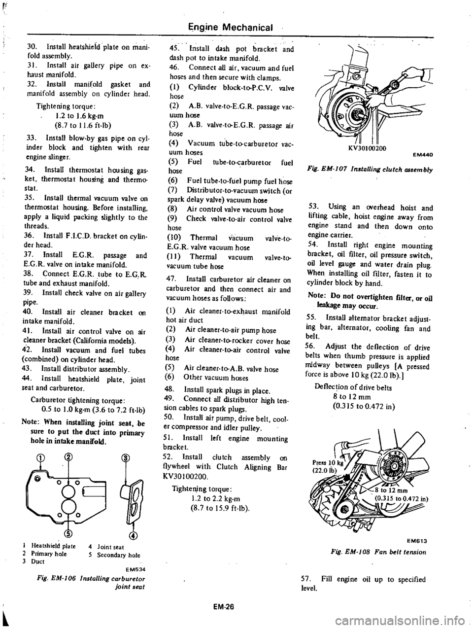
Note
When
instalUng
joint
seat
be
sure
to
put
the
duct
into
primary
hole
in
intake
manifold
S
J
Heatshield
plate
4
Joint
seat
2
Primary
hole
5
Secondary
hole
3
Duct
EM534
Fig
EM
I06
Installing
carburetor
joint
seat
Engine
Mechanical
45
Install
dash
pot
bracket
and
dash
pot
to
intake
manifold
46
Connect
all
air
vacuum
and
fuel
hoses
and
then
secure
with
clamps
I
Cylinder
block
to
P
C
V
valve
hose
2
A
B
valve
to
E
G
R
passage
vac
uum
hose
3
A
B
valve
to
E
G
R
passage
air
hose
4
Vacuum
tube
to
carburetor
vac
uum
hoses
5
Fuel
ube
to
carburetor
fuel
hose
6
Fuel
tube
to
fuel
pump
fuelhose
7
Distributor
to
vacuum
switch
or
spark
delay
valve
vacuum
hose
8
Air
control
valve
vacuum
hose
9
Check
valve
to
air
control
valve
hose
10
Thermal
vacuum
valve
to
E
G
R
valve
vacuum
hose
I
I
Thermal
vacuum
valve
to
vacuum
tube
hose
47
Install
carburetor
air
cleaner
on
carburetor
and
then
connect
air
and
vacuum
hoses
as
follows
I
Air
cleaner
to
exhaust
manifold
hot
air
duct
2
Air
c1eaner
to
air
pump
hose
3
Air
cleaner
to
rocker
cover
hose
4
Air
cleaner
to
air
control
valve
hose
5
6
48
Install
spark
plugs
in
place
49
Connect
all
distributor
high
ten
sion
cables
to
spark
plugs
50
Install
air
pump
drive
belt
cool
er
compressor
and
idler
pulley
51
Install
left
engine
mounting
bracket
52
Install
clutch
assembly
on
flywheel
with
Clutch
Aligning
Bar
KV30100200
Air
cleaner
to
A
B
valve
hose
Other
vacuum
hoses
Tightening
torque
1
2
to
2
2
kg
m
8
7
to
15
9
ft
lb
EM
26
I
I
KV30100200
EM440
Fig
EM
I07
In
talling
clutch
embly
53
Using
an
overhead
hoist
and
lifting
cable
hoist
engine
away
from
engine
stand
and
then
down
onto
engine
carrier
54
Install
right
engine
mounting
bracket
oil
filter
oil
pressure
switch
oil
level
gauge
and
water
drain
plug
When
installing
oil
filter
fasten
it
to
cylinder
block
by
hand
Note
Do
not
overtighten
flit
or
oil
leakage
may
occur
55
Install
alternator
bracket
adjust
ing
bar
alternator
cooling
fan
and
belt
56
Adjust
the
deflection
of
drive
belts
when
thumb
pressure
is
applied
midway
between
pulleys
A
pressed
force
is
above
10
kg
22
0
lb
Deflection
of
drive
belts
8
to
12
mm
0
315
to
0
472
in
EM613
Fig
EM
lOB
Fan
belt
tension
57
Fill
engine
oil
up
to
specified
level
Page 74 of 537
Engine
Mechanical
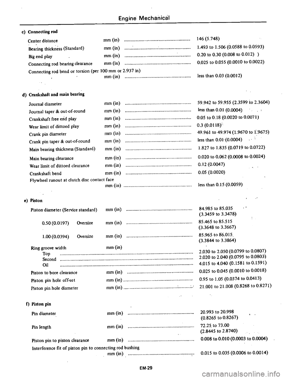
c
Connecting
rod
Center
distance
mm
in
Bearing
thickness
Standard
mm
in
Big
end
play
mm
in
Connecting
rod
bearing
clearance
mm
in
Connecting
rod
bend
or
torsion
per
100
mm
or
2
937
in
mm
in
d
Crankshaft
and
main
bearing
Journal
diameter
Journal
taper
out
of
round
Crankshaft
free
end
play
Wear
limit
of
dittoed
play
Crank
pin
diameter
Crank
pin
taper
out
of
round
Main
bearing
thickness
StJlndard
146
5
748
1
493
to
1
506
0
0588
to
0
0593
0
20
to
0
30
0
008
to
0
012
0
D25
to
0
055
0
0010
to
0
0022
less
than
0
03
0
0012
mm
in
mm
in
mm
in
mm
in
mm
in
mm
in
mm
in
59
942
to
59
955
2
3599
io
2
3604
less
than
0
0
I
0
0004
0
05
to
0
18
0
0020
to
0
0071
0
3
0
0118
49
961
to
49
974
1
9670
to
1
9675
less
than
0
01
0
0004
1
827
to
1
835
0
0719
to
0
0722
0
020
to
0
062
0
0008
to
0
0024
0
12
0
0047
0
05
0
0020
Main
bearing
clearance
mm
in
Wear
limit
of
dittoed
clearance
mm
in
Crankshaft
bend
mm
in
Flywheel
runout
at
clutch
disc
contact
face
mm
in
e
Piston
Pistondiarneter
Service
standard
0
50
0
0197
Oversize
1
00
0
0394
Oversize
Ring
groove
width
Top
Second
Oil
Piston
to
bore
clearance
Piston
pin
hole
off
set
Piston
pin
hole
diameter
f
Piston
pin
Pin
diameter
Pin
length
less
than
0
15
0
0059
mm
in
84
985
to
85
035
3
3459
to
3
3478
85
465
to
85
515
3
3648
to
3
3667
85
965
to
86
015
3
3844
to
3
3864
2
030
to
2
050
0
0799
to
0
0807
2
020
to
2
040
0
0795
to
0
0803
4
015
to
4
040
0
1581
to
0
1591
0
Q25
to
0
045
0
0010
to
0
0018
0
95
to
1
05
0
0374
to
0
0413
21
001
to
21
008
0
8268
to
0
8271
mm
in
mm
in
mm
in
mm
in
mm
in
mm
in
mm
in
20
993
to
20
998
0
8265
to
0
8267
72
25
to
73
00
2
8445
to
2
8740
0
008
to
om
0
0
0003
to
0
0004
mm
in
Piston
pin
to
piston
clearance
mm
in
Interference
fit
of
piston
pin
to
connecting
rod
bushing
mm
in
om
5
to
0
035
0
0006
to
0
00
I
4
EM
29
Page 75 of 537
Engine
Mechanical
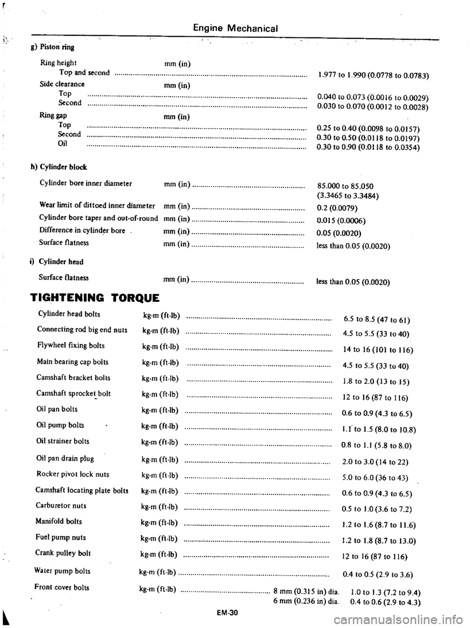
g
Piston
ring
Ring
height
Top
and
second
Side
clearance
Top
Second
Ring
gap
Top
Second
Oil
mm
in
mrn
in
mm
in
h
Cylinder
block
Cylinder
bore
inner
diameter
mm
in
Wear
limit
of
dittoed
inner
diameter
Cylinder
bore
taper
and
out
of
round
Difference
in
cylind
bore
Surface
flatness
mm
in
mm
in
mm
in
mm
in
i
Cylinder
head
Surface
flatness
mm
in
TIGHTENING
TORQUE
Cylinder
head
bolts
kg
m
fl
lb
Connecting
rod
big
end
nuts
kg
m
ft
Ib
Flywheel
fixing
bolts
kg
m
ft
Ib
Main
bearing
cap
bolts
kg
m
ft
lb
Camshaft
bracket
bolts
kg
m
ft
lb
Camshaft
sprocket
bolt
kg
m
ft
lb
Oil
pan
bolts
kg
m
ft
1b
Oil
pump
bolts
kg
m
ft
lb
Oil
strainer
bolts
kg
m
ft
lb
Oil
pan
drain
plug
kg
m
ft
lb
Rocker
pivot
lock
nuts
kg
m
ft
Ib
Camshaft
locating
plate
bolts
kg
m
ft
lb
Carburetor
nuts
kg
m
ft
lb
Manifold
bolts
kg
m
ft
lb
Fuel
pump
nuts
kg
m
ft
lb
Crank
pulley
bolt
kg
m
ft
lb
Water
pump
bolts
kg
m
ft
Ib
Front
cover
bolts
kg
m
ft
lb
EM
30
1
977
to
1
990
0
0778
to
0
0783
0
040
to
0
073
0
0016
to
0
0029
0
030
to
0
070
0
0012
to
0
0028
0
25
to
0
40
0
0098
to
0
0157
0
30
to
0
50
0
0118
to
0
0197
0
30
to
0
90
0
0118
to
0
0354
85
000
to
85
050
3
3465
to
3
3484
0
2
0
0079
om
5
0
0006
0
05
0
0020
less
than
0
05
0
0020
less
than
0
05
0
0020
6
5
to
8
5
47
to
61
4
5
to
5
5
33
to
40
14
to
16
101
to
116
4
5
to
5
5
33
to
40
1
8
to
2
0
13
to
15
12
to
16
87
to
116
0
6
to
0
9
4
3
to
6
5
I
J
to
1
5
8
0
to
10
8
0
8
to
1
1
5
8
to
8
0
2
0
to
3
0
14
to
22
5
0
to
6
0
36
to
43
0
6
to
0
9
4
3
to
6
5
0
5
to
1
0
3
6
to
7
2
1
2
to
1
6
8
7
to
11
6
1
2
to
1
8
8
7
to
13
0
12
to
16
87
to
116
0
4
to
0
5
2
9
to
3
6
8
mm
0
315
in
dia
6
mm
0
236
in
dia
1
0
to
1
3
7
2
to
9
4
0
4
to
0
6
2
9
to
4
3
Page 92 of 537
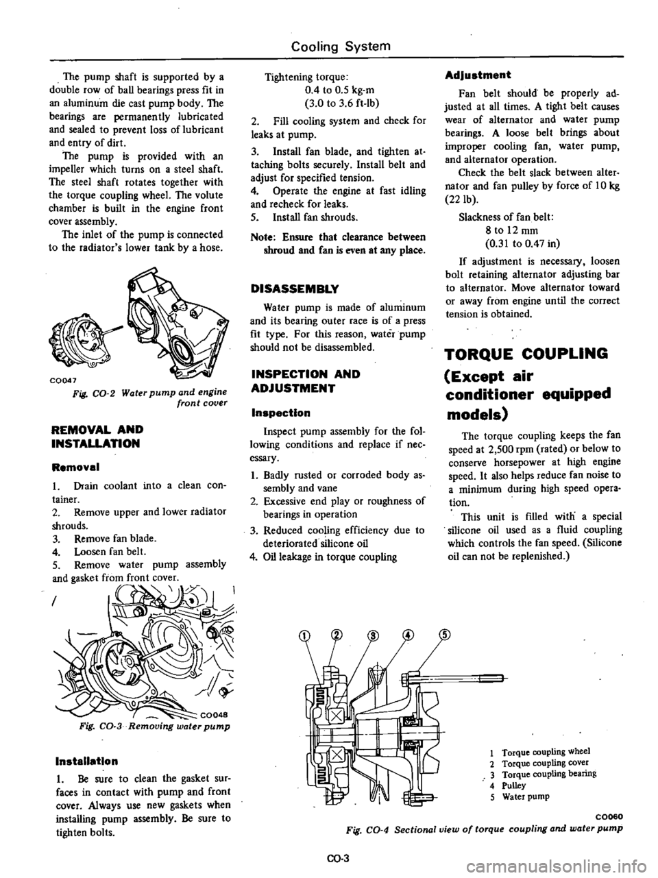
The
pump
shaft
is
supported
by
a
double
row
of
ball
bearings
press
fit
in
an
aluminum
die
cast
pump
body
The
bearings
are
permanently
lubricated
and
sealed
to
prevent
loss
of
lubricant
and
entry
of
dirt
The
pump
is
provided
with
an
impeller
which
turns
on
a
steel
shaft
The
steel
shaft
rotates
together
with
the
torque
coupling
wheeL
The
volute
chamber
is
built
in
the
engine
front
cover
assembly
The
inlet
of
the
pump
is
connected
to
the
radiator
s
lower
tank
by
a
hose
i
o
CQ047
Fig
CO
2
Water
pump
and
engine
front
cover
REMOVAL
AND
INSTALLATION
Removal
in
to
a
clean
con
assembly
I
CQ048
Fig
CO
3
Removing
water
pump
Installation
1
Be
sure
to
clean
the
gasket
sur
faces
in
contact
with
pump
and
front
cover
Always
use
new
gaskets
when
installing
pump
assembly
Be
sure
to
tighten
bolts
Cooling
System
Tightening
torque
0
4
to
0
5
kg
m
3
0
to
3
6
ft
lb
2
Fill
cooling
system
and
check
for
leaks
at
pump
3
Install
fan
blade
and
tighten
at
taching
bolts
securely
Install
belt
and
adjust
for
specified
tension
4
Operate
the
engine
at
fast
idling
and
recheck
for
leaks
5
Install
fan
shrouds
Note
Ensure
that
clearance
between
shroud
and
Can
is
even
at
any
place
DISASSEMBLY
Water
pump
is
made
of
aluminum
and
its
bearing
outer
race
is
of
a
press
fit
type
For
this
reason
water
pump
should
not
be
disassembled
INSPECTION
AND
ADJUSTMENT
Inspection
Inspect
pump
assembly
for
the
fol
lowing
conditions
and
replace
if
nee
essary
1
Badly
rusted
or
corroded
body
as
sembly
and
vane
2
Excessive
end
play
or
roughness
of
bearings
in
operation
3
Reduced
cooling
efficiency
due
to
deteriorated
silicone
oil
4
Oil
leakage
in
torque
coupling
Adjustment
Fan
belt
should
be
properly
ad
justed
at
all
times
A
tight
belt
causes
wear
of
alternator
and
water
pump
bearings
A
loose
belt
brings
about
improper
cooling
fan
water
pump
and
alternator
operation
Check
the
belt
slack
between
alter
nator
and
fan
pulley
by
force
of
10
kg
22
lb
Slackness
of
fan
belt
8
to
12
mm
0
31
to
0
47
in
If
adjustment
is
necessary
loosen
bolt
retaining
alternator
adjusting
bar
to
alternator
Move
alternator
toward
or
away
from
engine
until
the
correct
tension
is
obtained
TORQUE
COUPLING
Except
air
conditioner
equipped
models
The
torque
coupling
keeps
the
fan
speed
at
2
500
rpm
rated
or
below
to
conserve
horsepower
at
high
engine
speed
It
also
helps
reduce
fan
noise
to
a
minimum
during
high
speed
opera
tion
This
unit
is
filled
with
a
special
silicone
oil
used
as
a
fluid
coupling
which
controls
the
fan
speed
Silicone
oil
can
not
be
replenished
1
Torque
coupling
wheel
2
Torque
coupling
cover
3
Torque
coupling
bearing
4
Pulley
5
Water
pump
C0060
Fig
CO
4
Sectional
view
of
torque
coupling
and
water
pump
00
3
Page 117 of 537
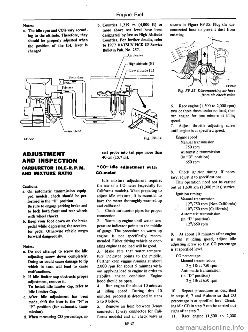
Notes
a
The
idle
rpm
and
CO
vary
accord
ing
to
the
altitude
Therefore
they
should
be
properly
adjusted
when
the
position
of
the
H
L
lever
is
changed
EF729
ADJUSTMENT
AND
INSPECTION
CARBURETOR
IDLE
R
P
M
AND
MIXTURE
RATIO
Cautions
3
On
automatic
transmission
equi
ped
models
check
should
be
per
formed
in
the
0
position
Be
sure
to
engage
parking
brake
and
to
lock
both
front
and
rear
wheels
with
wheel
chocks
b
Keep
your
foot
down
on
the
brake
pedal
while
depressing
the
accelera
tor
pedal
Otherwise
vehicle
surges
forward
dangerously
Notes
a
00
not
attempt
to
screw
the
idle
adjusting
screw
down
completely
Ooing
so
could
cause
damage
to
tip
which
in
turn
will
tend
to
cause
malfunctio11ll
b
If
idle
limiter
cap
obstructs
proper
adjustment
remove
it
To
install
idle
limiter
cap
refer
to
Idle
Limiter
Cap
c
After
idle
adjustment
has
been
made
shift
the
lever
to
the
N
or
P
position
for
automatic
trans
mission
d
When
measuring
CO
percentage
in
Engine
Fuel
b
Counties
1
219
m
4
000
ft
or
more
above
sea
level
have
been
designated
by
law
as
High
Altitude
Counties
For
further
details
refer
to
1977
OATSUN
PICK
UP
Service
Bulletin
Pub
No
257
0
I
Air
cleaner
rID
mOl
If
Low
altitude
Ll
n
n
L
n
Fig
EF
34
sert
probe
into
tail
pipe
more
than
40
em
15
7
in
CO
Idle
adjustment
with
CO
meter
Idle
mixture
adjustment
requires
the
use
of
a
CO
meter
especially
for
California
models
When
preparing
to
adjust
idle
mixture
it
is
essential
to
have
the
meter
thoroughly
warmed
up
and
calibrated
I
Check
carburetor
pipes
for
proper
connection
2
Warm
up
engine
until
water
tem
perature
indicator
points
to
the
middle
of
gauge
The
procedure
to
warm
up
engine
is
not
specifically
recom
mended
Either
driving
vehicle
or
oper
ating
engine
at
no
load
will
be
good
3
Make
sure
that
water
tempera
ture
indicator
points
to
the
middle
Further
keep
engine
running
at
about
2
000
rpm
for
about
5
minutes
with
out
applying
load
to
engine
in
order
to
stabilize
engine
condition
Engine
hood
should
be
open
4
Run
engine
for
about
10
minutes
at
idling
speed
Ouring
this
10
minutes
proceed
as
described
in
steps
5
to
9
below
5
Remove
air
hose
between
3
way
connector
5
way
connector
for
Cali
fornia
models
and
air
check
valve
as
EF
21
shown
in
Figure
EF
35
Plug
the
dis
connected
hose
to
prevent
dust
from
entering
0
o
EF259
Fig
EF
35
Disconnecting
air
hose
from
air
check
valve
6
Race
engine
I
500
to
2
000
rpm
two
or
three
times
under
no
load
then
run
engine
for
one
minute
at
idling
speed
7
Adjust
throttle
adjusting
screw
until
engine
is
at
specified
speed
Engine
speed
Manual
transmission
750
rpm
Automatic
transmission
in
0
position
650
rpm
8
Check
ignition
timing
If
neces
sary
adjust
it
to
specifications
This
operation
need
not
be
carried
out
at
1
600
Ian
1
000
miles
service
Ignition
timing
Manual
transmission
120
750
rpm
Non
California
100
750
rpm
California
Automatic
transmission
in
0
position
120
650
rpm
9
At
about
10
minutes
after
engine
is
run
at
idling
speed
adjust
idle
adjusting
screw
so
that
CO
percentage
is
at
specified
level
CO
percentage
Manual
transmission
2
t
l
at
750
rpm
Automatic
transmission
in
0
position
2
t
I
at
650
rpm
10
Repeat
procedures
as
described
in
steps
6
7
and
9
above
so
that
CO
percentage
is
at
specified
level
Check
ing
idle
CO
in
step
9
can
be
carried
out
right
after
step
7
II
Race
engine
1
500
to
2
000
Page 155 of 537
j
EC231
Thermal
vacuum
valva
o
o
m
Emission
Control
System
0
o
o
o
l
l
@
The
thermal
vacuum
valve
is
mounted
in
the
engine
thermostat
housing
It
detects
engine
coolan
t
tem
perature
by
means
of
a
built
in
bi
metal
and
opensor
closes
the
vacuum
passage
in
the
thermal
vacuum
valve
mt
li
t
00
t
EC232
Fig
EC
54
Thennal
vacuum
valve
To
E
G
R
control
valve
From
carburetor
1
Spring
2
Bi
metal
3
O
ring
E
G
R
warning
system
The
E
G
R
warning
system
install
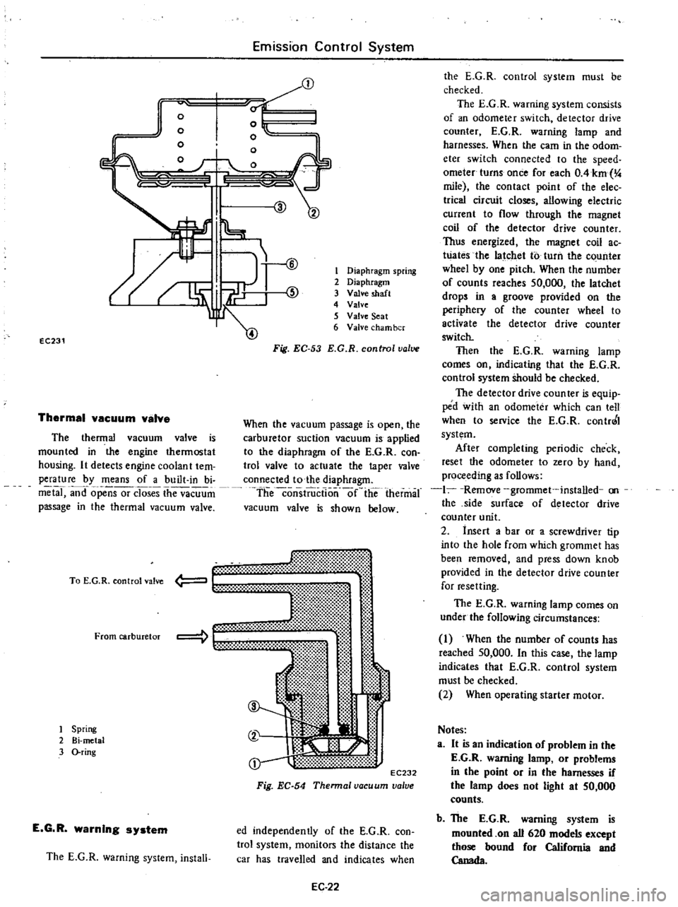
1
Diaphragm
spring
2
Diaphragm
3
Valve
shaft
4
Valve
5
Valve
Seat
6
Valve
cham
ber
Fig
EC
53
E
G
R
control
value
When
the
vacuum
passage
is
open
the
carburetor
suction
vacuum
is
applied
to
the
diaphragm
of
the
E
G
R
con
trol
valve
to
actuate
the
taper
valve
connected
to
the
diaphragm
theconsiiiictlo
nlie
thermal
vacuum
valve
is
shown
below
ed
independently
of
the
E
G
R
con
trol
system
monitors
the
distance
the
car
has
travelled
and
indicates
when
EC
22
the
E
G
R
control
system
must
be
checked
The
E
G
R
warning
system
consists
of
an
odometer
switch
detector
drive
counter
E
G
R
warning
lamp
and
harnesses
When
the
earn
in
the
odom
eter
switch
connected
to
the
speed
ometer
turns
once
for
each
OAkm
4
mile
the
contact
point
of
the
elec
trica
circuit
closes
allowing
electric
current
to
flow
through
the
magnet
coil
of
the
detector
drive
counter
Thus
energized
the
magnet
coil
ac
Wates
the
latchet
to
turn
the
c
unter
wheel
by
one
pitch
When
the
number
of
counts
reaches
50
000
the
latchet
drops
in
a
groove
provided
on
the
periphery
of
the
counter
wheel
to
activate
the
detector
drive
counter
switch
Then
the
E
G
R
warning
lamp
comes
on
indicating
that
the
E
G
R
control
system
Should
be
checked
The
detector
drive
coun
teT
is
equip
ped
with
an
odometer
which
can
tell
when
to
service
the
E
G
R
contr0
I
system
After
completing
periodic
check
reset
the
odometer
to
zero
by
hand
proceeding
as
follows
1
Remove
grommet
installed
on
the
side
surface
of
detector
drive
counter
unit
2
insert
a
bar
or
a
screwdriver
tip
into
the
hole
from
which
grommet
has
been
removed
and
press
down
knob
provided
in
the
detector
drive
counter
for
resetting
The
E
G
R
warning
lamp
comes
on
under
the
following
circumstances
1
When
the
number
of
counts
has
reached
50
000
In
this
case
the
lamp
indicates
that
E
G
R
control
system
must
be
checked
2
When
operating
starter
motor
Notes
a
It
is
an
indication
of
problem
in
the
E
G
R
warning
lamp
or
problems
in
the
point
or
in
the
harnesses
if
the
lamp
does
not
light
at
50
000
counts
b
The
E
G
R
warning
system
is
mounted
on
all
620
models
except
those
bound
for
California
and
Canada
Page 160 of 537
REMOVAL
AND
INSPECTION
Removal
and
inspection
can
be
done
as
follows
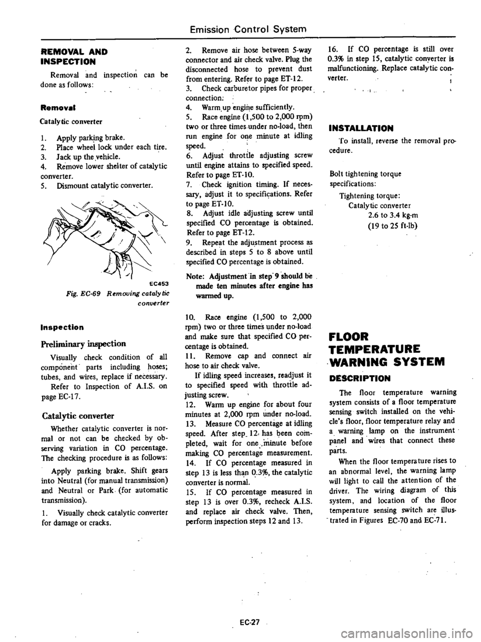
Removal
Catalytic
converter
1
Apply
parking
brake
2
Place
wheel
lock
under
each
tire
3
Jack
up
the
vehicle
4
Remove
lower
shelter
of
catalytic
converter
5
Dismount
catalytic
converter
EC453
Fig
EC
69
Removing
catalytic
conuerter
Inspection
Preliminary
inspection
Visually
check
condition
of
all
component
parts
including
ho
s
tubes
and
wires
replace
if
necessary
Refer
to
Inspection
of
A
I
S
on
page
EC
17
Catalytic
converter
Whether
catalytic
converter
is
nor
mal
or
not
can
be
checked
by
ob
serving
variation
in
CO
percentage
The
checking
procedure
is
as
follows
Apply
parking
brake
Shift
gears
into
Neutral
for
manual
transmission
and
Neutral
or
Park
for
automatic
transmission
1
Visually
check
catalytic
converter
for
damage
or
cracks
Emission
Control
System
2
Remove
air
hose
between
5
way
connector
and
air
check
valve
Plug
the
disconnected
hose
to
prevent
dust
from
entering
Refer
to
page
ET
12
3
Check
carburetor
pipes
for
proper
connection
4
Warm
up
engine
sufficiently
5
Race
engine
1
500
to
2
000
rpm
two
or
three
times
under
no
load
then
run
engine
for
o
e
minute
at
idling
speed
6
Adjust
throttle
adjusting
screw
until
engine
attains
to
specified
speed
Refer
to
page
ET
10
7
Check
ignition
timing
If
neces
sary
adjust
it
to
specifkations
Refer
to
page
ET
10
B
Adjust
idle
adjusting
screw
until
specified
CO
percentage
is
obtained
Refer
to
page
ET
12
9
Repeat
the
adju
stment
process
as
described
in
steps
5
to
8
above
until
specified
CO
percentage
is
obtained
Note
Adjustment
in
step
9
should
be
made
ten
minutes
after
engine
has
wanned
up
10
Race
engine
1
500
to
2
000
rpm
two
or
three
times
under
no
load
and
make
sure
that
specified
CO
per
centage
is
obtained
11
Remove
cap
and
connect
air
hose
to
air
check
valve
If
idling
speed
increases
readjust
it
to
specified
speed
with
throttle
ad
justing
screw
12
WaRn
up
engine
for
about
four
minutes
at
2
000
rpm
under
no
load
13
Measure
CO
percentage
at
idling
speed
After
step
12
has
been
coin
pleted
wait
for
one
minute
before
making
CO
percentage
measurement
14
If
CO
percentage
measured
in
step
13
is
less
than
0
3
the
catalytic
converter
is
normal
15
If
CO
percentage
measured
in
step
13
is
over
0
3
recheck
A
I
S
and
replace
air
check
valve
Then
perform
inspection
steps
12
and
13
EC
27
16
If
CO
percentage
is
still
over
0
3
in
step
15
catalytic
conyerter
is
malfunctioning
Replace
catalytic
con
verter
INSTALLATION
To
install
reverse
the
removal
pro
cedure
Bolt
lightening
torque
specifications
Tightening
torque
Catalytic
converter
2
6
to
3
4
kg
m
19
to
25
ft
Ib
FLOOR
TEMPERATURE
WARNING
SYSTEM
DESCRIPTION
The
floor
temperature
warning
system
consists
of
a
floor
temperature
sensing
switch
installed
on
the
vehi
cle
s
floor
floor
temperature
relay
and
a
warning
lamp
on
the
instrument
panel
and
wires
that
connect
these
parts
When
the
floor
tempera
ture
rises
to
an
abnormal
level
the
warning
lamp
will
light
to
call
the
attention
of
the
driver
The
wiring
diagram
of
this
system
and
location
of
the
floor
temperature
sensing
switch
are
ilIus
trated
in
Figures
EC
70
and
EC
71
Page 173 of 537
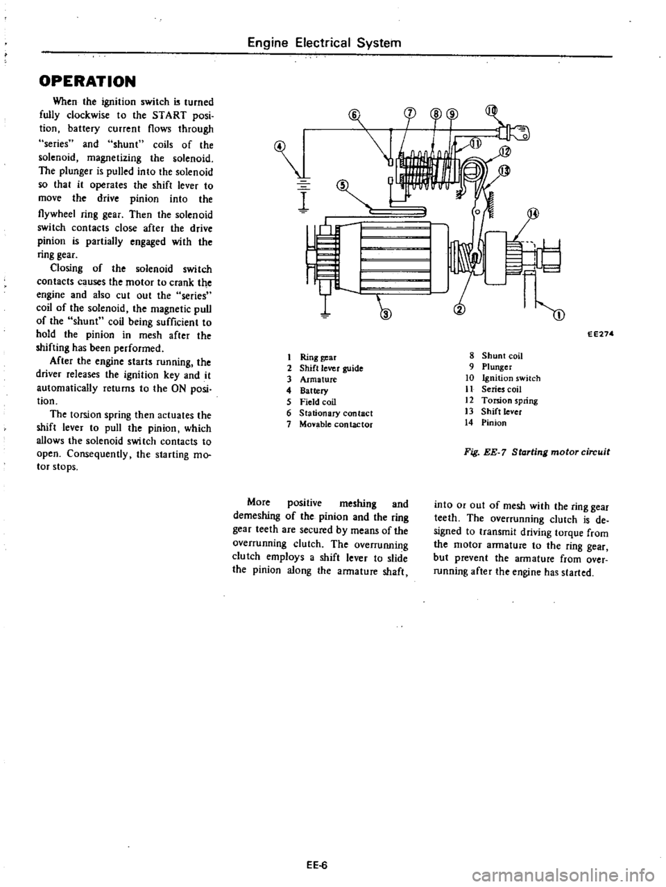
OPERATION
When
the
ignition
switch
turned
fully
clockwise
to
the
START
posi
tion
battery
current
flows
through
series
and
shunt
coils
of
the
solenoid
magnetizing
the
solenoid
The
plunger
is
pulled
into
the
solenoid
so
that
it
operates
the
shift
lever
to
move
the
drive
pinion
into
the
flywheel
ring
gear
Then
the
solenoid
switch
contacts
close
after
the
drive
pinion
is
partially
engaged
with
the
ring
gear
Closing
of
the
solenoid
switch
contacts
c
uses
the
motor
to
crank
the
engine
and
also
cut
out
the
series
coil
of
the
solenoid
the
magnetic
pull
of
the
shunt
coil
being
sufficient
to
hold
the
pinion
in
mesh
after
the
shifting
has
been
performed
After
the
engine
starts
running
the
driver
releases
the
ignition
key
and
it
automatically
returns
to
the
ON
posi
tion
The
torsion
spring
then
actuates
the
shift
lever
to
pull
the
pinion
which
allows
the
solenoid
swi
tch
contacts
to
open
Consequently
the
starting
mo
tor
stops
Engine
Electrical
System
I
I
Ring
gear
2
Shift
lever
guide
3
Armature
4
Battery
5
Field
coil
6
Stationary
contact
7
Monble
contactor
More
positive
meshing
and
demeshing
of
the
pinion
and
the
ring
gear
teeth
are
secured
by
means
of
the
overrunning
clutch
The
overruIUling
clutch
employs
a
shift
lever
to
slide
the
pinion
along
the
armature
shaft
EE
6
F
l
cp
o
r
1
I
I
W
m
EE274
8
Shunt
coil
9
Plunger
10
Ignition
switch
11
Series
coil
12
Torsion
spring
13
Shift
lever
14
Pinion
Fig
EE
7
Starting
motor
circuit
into
or
out
of
mesh
with
the
ring
gear
teeth
The
overrunning
clutch
is
de
signed
to
transmit
driving
torque
from
the
motor
armature
to
the
ring
gear
but
prevent
the
armature
from
over
running
after
the
engine
has
started
Page 176 of 537

L
0
5
to
0
8
mm
71j
Correct
2
Inspect
soldered
connection
of
armature
lead
and
commutator
If
loose
connection
is
found
solder
it
using
resin
flux
3
Armature
test
for
ground
Using
a
circuit
tester
place
one
test
probe
onto
armature
shaft
and
other
onto
each
commutator
bar
If
tester
shows
continuity
armature
is
grounded
and
must
be
replaced
EE022
Fig
EE
16
Testing
annature
for
ground
4
Check
armature
for
short
by
placing
it
on
armature
tester
growler
with
a
piece
of
iron
over
armature
core
rotating
armature
If
the
plate
vibrates
armature
is
shorted
j
l
EE023
Fig
EE
17
Testing
annature
for
ahort
Engine
Electrical
System
L
File
l
0
Commutator
Segmen
t
IWMica
Incorrect
EE021
Fig
EE
15
Undercutting
i118ulating
mica
5
Check
armature
for
continuity
by
placing
probes
of
tester
on
two
seg
ments
side
by
side
If
tester
shows
no
continuity
the
circuit
is
open
OVERRUNNING
CLUTCH
ASSEMBLY
Inspect
pinion
assembly
and
screw
sleeve
Screw
sleeve
must
slide
freely
along
armature
shaft
splines
If
damage
is
found
or
resistance
is
felt
when
sliding
it
must
be
repaired
Inspect
pinion
teeth
If
excessive
rub
bing
is
found
on
teeth
replace
Flywheel
ring
gear
also
must
be
in
spected
l
EE278
Fig
EE
18
Overrunning
clutch
auem
bly
BRUSH
HOLDER
TEST
FOR
GROUND
Using
a
circuit
tester
place
one
test
probe
onto
negative
side
of
brush
holder
and
another
onto
positive
side
If
tester
shows
continuity
brush
holder
is
shorted
to
ground
Replace
brush
holder
EE
9
Ee026
Fig
EE
19
Testing
brush
for
round
BEARING
METAL
Inspect
bearing
metal
for
wear
or
side
play
If
the
clearance
between
bearing
metal
and
armature
shaft
is
more
than
0
2
mm
0
0079
in
replace
metal
MAGNETIC
SWITCH
ASSEMBLY
1
Using
a
circuit
tester
l
check
con
tinuity
between
S
terminal
of
mag
netic
switch
and
switch
body
metal
If
continuity
does
not
exist
shunt
coit
is
opened
Replace
switch
assembly
2
In
the
same
manner
as
above
check
continuity
between
terminals
S
and
M
If
continuity
does
not
exist
series
coil
is
opened
Replace
switch
assembly
ASSEMBLY
Reassemble
starting
motor
in
re
verse
sequence
of
disassembly
When
assembling
be
sure
to
apply
grease
to
gear
case
and
rear
cover
bearing
metal
and
apply
oil
lightly
to
pinion
TEST
PERFORMANCE
TEST
Starter
motor
should
be
subjected
to
a
no
load
test
whenever
it
has
been
overhauled
to
ensure
that
its
performance
will
be
satisfactory
when
installed
on
engine
Starter
motor
should
also
be
subjected
to
the
test
when
the
cause
of
abnormal
operation
is
to
be
determined
A
brief
outline
of
the
test
is
given
below