service DATSUN PICK-UP 1977 Service Manual
[x] Cancel search | Manufacturer: DATSUN, Model Year: 1977, Model line: PICK-UP, Model: DATSUN PICK-UP 1977Pages: 537, PDF Size: 35.48 MB
Page 3 of 537
FOREWORD
This
service
manual
has
been
prepared
for
the
purpose
of
assisting
service
personnel
of
authorized
NISSAN
DATSUN
dealers
fu
providing
effective
service
and
maintenance
of
the
1977
Datsun
Pick
up
Since
proper
maintenance
and
service
are
absolutely
essential
fu
satisfying
the
Datsun
owners
this
inan
la1
should
be
kept
fu
a
handy
place
for
ready
reference
and
should
be
carefuny
studied
This
man
la1
fucludes
procedures
for
ma
futenance
ac
1justrnents
minor
service
operations
remowl
and
installation
and
for
disassembly
and
assembly
of
components
Some
of
these
service
operations
require
the
use
of
Special
Tools
especially
designed
for
effectiveperfonnance
of
service
operations
The
special
tools
are
presented
in
the
SE
section
As
you
read
through
the
maintenance
procedures
in
this
service
manual
you
will
occasionally
corne
across
paragraphs
headed
NOTE
or
CAUTION
A
NOTE
is
supplemental
infortl1ation
that
is
important
to
B
particular
procedure
CAUTION
warns
of
steps
that
must
be
fonowed
to
prevent
personal
injury
and
Qr
damage
to
some
part
of
your
DATSUN
The
Quick
Reference
Index
on
the
first
page
enables
the
user
to
quickly
locate
the
desired
section
At
the
beginning
of
each
individual
section
is
a
table
of
contents
which
gives
the
page
number
on
which
each
major
subject
begins
An
index
is
placed
at
the
beginning
of
each
major
subject
within
the
section
All
information
illustrations
and
specifications
contained
in
this
manual
are
based
on
the
latest
product
information
available
at
the
time
of
publication
approval
If
YOUT
DATSUN
model
differs
from
the
specifications
contained
in
this
manual
consult
your
NlSSAN
DATSUN
dealer
for
information
Rights
for
alteratiohat
any
time
of
specifications
and
methods
are
reserved
liability
for
any
personal
injury
or
property
damage
occasioned
by
the
use
of
this
service
man
la1
in
effecting
maintenance
or
repair
of
your
Datsun
is
in
no
way
assumed
by
Nissan
M9tor
Co
Ltd
Accordingly
anyone
using
a
service
procedure
or
tool
which
is
not
specifically
w
mended
by
Nissan
must
fust
completely
satisfy
himself
that
neither
his
safety
nor
the
vehicle
s
safety
wi11be
jeopardized
by
the
service
method
selected
NISSAN
MOTOR
CO
LTD
TOKYO
JAPAN
@
1976
N1SSAN
MOTOR
CO
LTD
Printed
in
Japan
Page 8 of 537
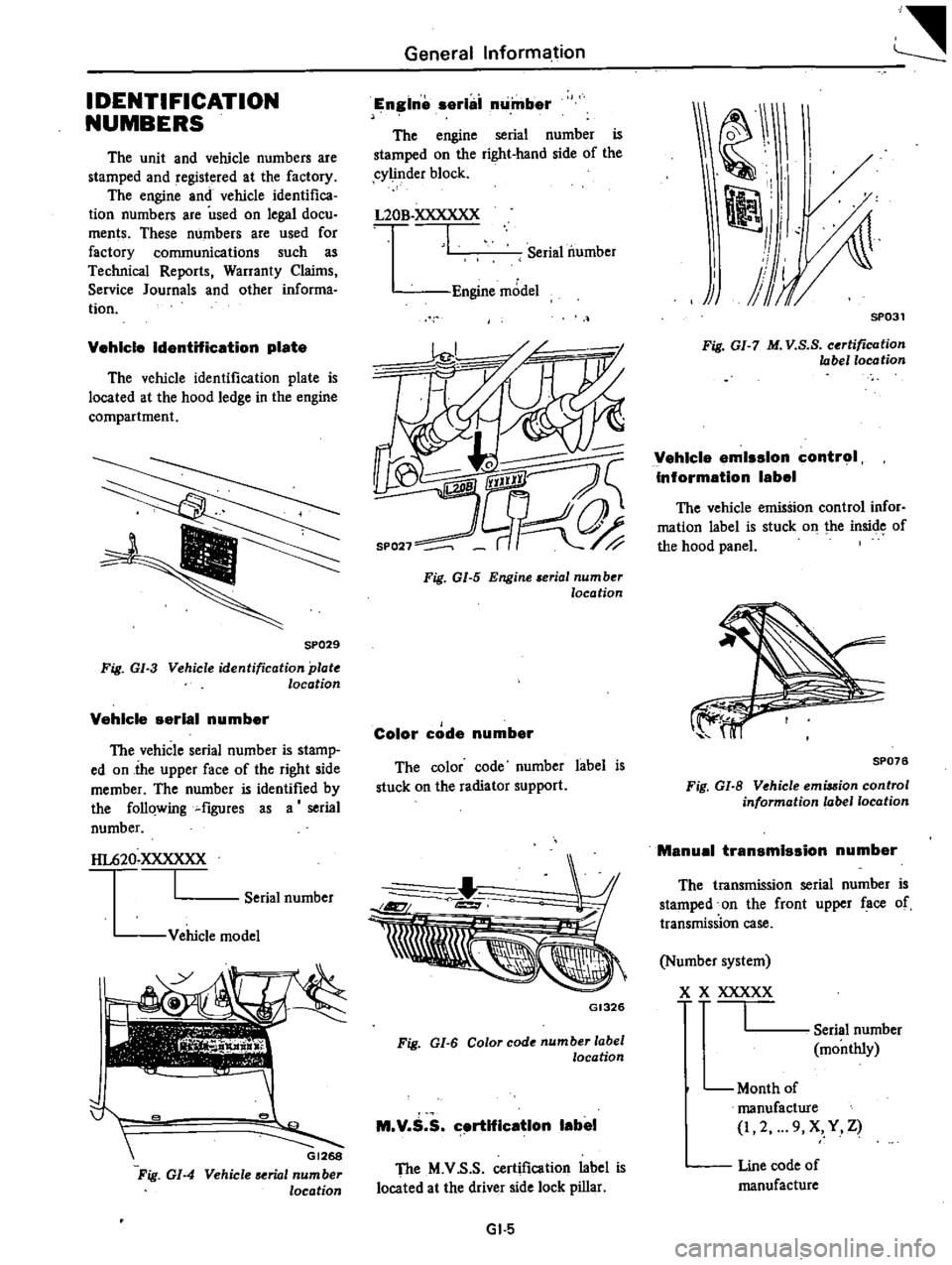
IDENTIFICATION
NUMBERS
The
unit
and
vehicle
numbers
are
stamped
and
registered
at
the
factory
The
engine
and
vehicle
identifica
tion
numbers
are
used
on
legal
docu
ments
These
numbers
are
used
for
factory
communications
such
as
Technical
Reports
Warranty
Claims
Service
Journals
and
other
informa
tion
Vehicle
IdentHication
plate
The
vehicle
identification
plate
is
located
at
the
hood
ledge
in
the
engine
compartment
SP029
Fig
GI
3
Vehicle
identification
plat
location
Vehicle
serial
number
The
vehicle
serial
number
is
stamp
ed
on
the
upper
face
of
the
right
side
member
The
number
is
identified
by
the
follQwing
flgUres
as
a
serial
number
HL620
XXXXXX
I
Serial
number
Vehicle
model
j
e
G1268
Vehicle
serial
number
location
Fig
GI
4
General
Informa
tion
Engine
serllii
number
The
engine
serial
number
is
stamped
on
the
right
hand
side
of
the
cylinder
block
L20B
XXXXXX
I
Serial
number
Engine
model
k
Color
code
number
The
color
code
number
label
is
stuck
on
the
radiator
support
GI326
Fig
01
6
Color
code
number
label
location
M
V
S
S
c
rtlflcatlon
label
The
M
V
S
S
certification
label
is
located
at
the
driver
side
lock
pillar
Gl
5
tW
I
1
I
il
j
SP031
Fig
GI
7
M
V
S
S
certification
label
location
Vehicle
emission
control
Information
label
The
vehicle
emission
control
infor
mation
label
is
stuck
on
the
insicre
of
the
hood
panel
SP076
Fig
GI
B
Vehicle
emia
ion
control
information
label
location
Manual
transmission
number
The
transmission
serial
number
is
stamped
on
the
front
upper
face
of
transmission
case
Number
system
x
X
XXXXX
I
Serial
number
monthly
Month
of
manufacture
2
9
X
Y
Z
Line
code
of
manufacture
Page 13 of 537
DATSUN
PICK
UP
MODEL
620
SERIES
I
NISSAN
I
NISSAN
MOTOR
CO
LTD
TOKYO
JAPAN
SECTION
ET
ENGINE
TUNE
UP
ENGINE
TUNE
UP
ET
2
BASIC
MECHANICAL
SySTEM
ET
7
IGNITION
AND
FUEL
SYSTEM
EMISSION
CONTROL
SYSTEM
ET
13
SERVICE
DATA
AND
ET
25
SPECIFICATIONS
TROUBLE
DIAGNOSES
AND
CORRECTIONS
ET
9
H
27
Page 19 of 537
Engine
Tune
up
BASIC
MECHANICAL
SYSTEM
ADJUSTING
INTAKE
AND
EXHAUST
VALVE
CLEARANCE
CHECKING
AND
ADJUSTING
DRIVE
BELT
RETIGHTENING
CYLINDER
HEAD
BOLTS
MANIFOLD
NUTS
AND
CARBURETOR
SECURING
NUTS
CHECKING
ENGINE
OIL
REPLACING
OIL
FILTER
CHANGING
ENGINE
COOLANT
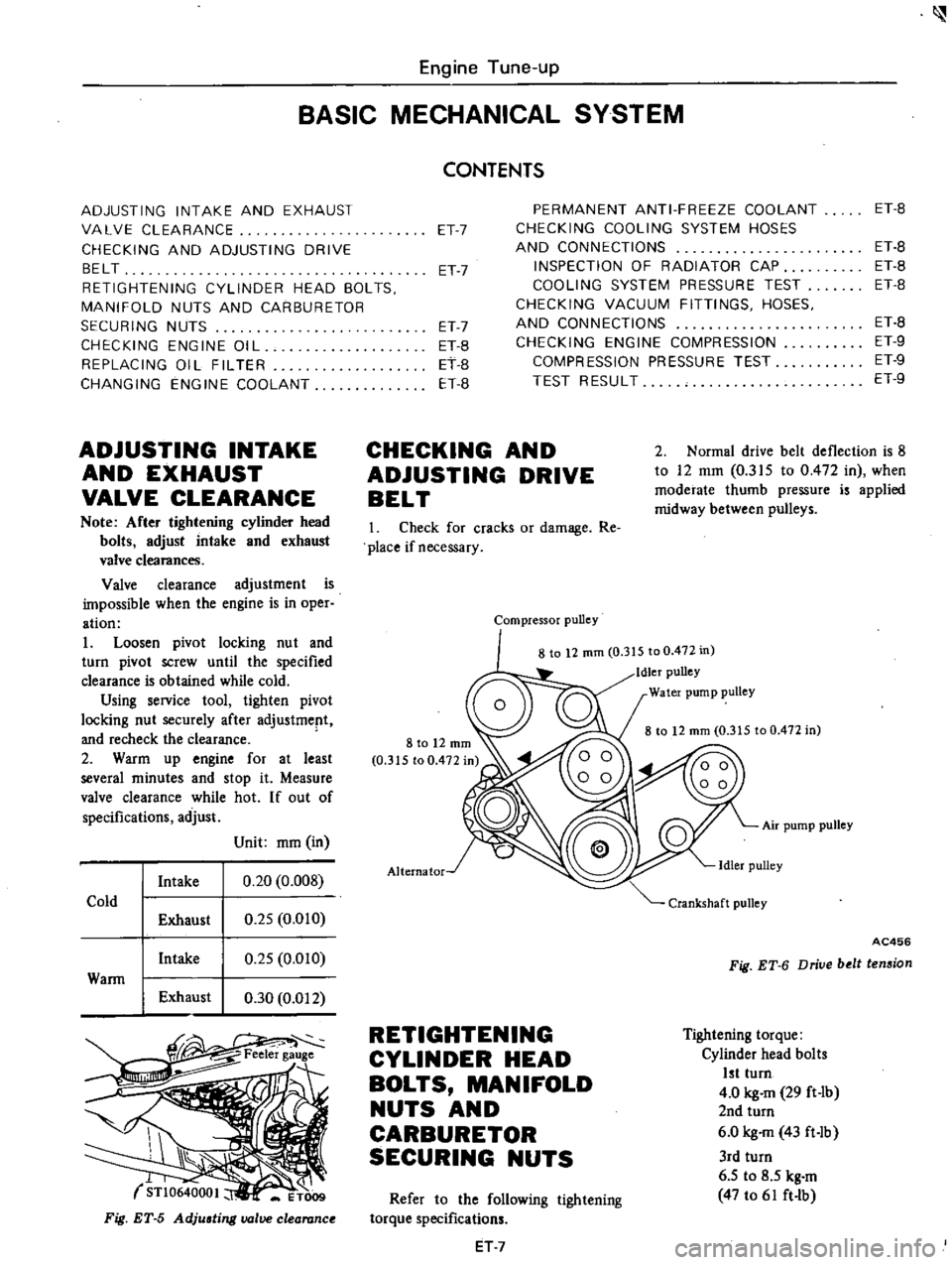
ADJUSTING
INTAKE
AND
EXHAUST
VALVE
CLEARANCE
Note
After
tightening
cylinder
head
bolts
adjust
intake
and
exhaust
valve
clearances
Valve
clearance
adjustment
is
impossible
when
the
engine
is
in
oper
ation
1
Loosen
pivot
locking
nu
t
and
turn
pivot
screw
until
the
specified
clearance
is
obtained
while
cold
Using
service
tool
tighten
pivot
locking
nut
securely
after
adjustment
and
recheck
the
clearance
2
Warm
up
engine
for
at
least
several
minutes
and
stop
it
Measure
valve
clearance
while
hot
If
out
of
specifications
adjust
Unit
mm
in
Intake
0
20
0
008
Cold
Exhaust
0
25
0
010
Intake
0
25
OmO
Wann
I
Exhaust
0
30
0
012
STl
064000
I
ET009
Fig
ET
5
Adjusting
valve
clearance
CONTENTS
ET
7
PERMANENT
ANTI
FREEZE
COOLANT
CHECKING
COOLING
SYSTEM
HOSES
AND
CONNECTIONS
INSPECTION
OF
RADIATOR
CAP
COOLING
SYSTEM
PRESSURE
TEST
CHECKING
VACUUM
FITTINGS
HOSES
AND
CONNECTIONS
CHECKING
ENGINE
COMPRESSION
COMPRESSION
PRESSURE
TEST
TEST
RESULT
ET
7
ET7
ET
B
ET
B
ET
B
CHECKING
AND
ADJUSTING
DRIVE
BELT
ET
B
ET
B
ET
B
ET
B
ET
B
ET
9
ET
9
ET
9
2
Normal
drive
belt
deflection
is
8
to
12
mm
0
315
to
0
472
in
when
moderate
thumb
pressure
is
applied
midway
between
pulleys
1
Check
for
cracks
or
damage
Re
place
if
necessary
Compressor
pulley
8
to
12
mm
0
315
to
0
472
in
Idler
pulley
Water
pump
pulley
8
to
12
mm
0
315
to
0
472
in
Air
pump
pulley
Alternator
AC456
Fig
ET
6
Driue
belt
tension
RETIGHTENING
CYLINDER
HEAD
BOLTS
MANIFOLD
NUTS
AND
CARBURETOR
SECURING
NUTS
Tightening
torque
Cylinder
head
bolts
1st
turn
4
0
kg
m
29
ft
Ib
2nd
turn
6
0
kg
m
43
ft
Ib
3rd
turn
6
5
to
8
5
kg
m
47
to
61
ft
lb
Refer
to
the
following
tightening
torque
specifications
ET
7
Page 24 of 537
r
connected
hose
to
prevent
dust
from
entering
To
air
check
valve
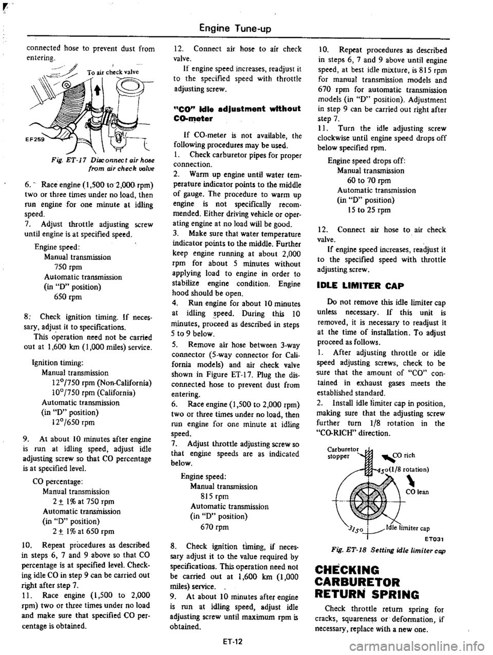
Fig
ET
17
Disconnect
air
hose
from
ojr
check
valve
6
Race
engine
1
500
to
2
000
rpm
two
or
three
times
under
no
load
then
run
engine
for
one
minute
at
idling
speed
7
Adjust
throttle
adjusting
screw
until
engine
is
at
specified
speed
Engine
speed
Manual
transmission
750
rpm
Automatic
transmission
in
D
position
650
rpm
8
Check
ignition
timing
If
neces
sary
adjust
it
to
specifications
This
operation
need
not
be
carried
out
at
1
600
Ian
1
000
miles
service
Ignition
timing
Manual
transmission
120
750
rpm
Non
California
100
750
rpm
California
Automatic
transmission
in
D
position
120
650
rpm
9
At
about
10
minutes
after
engine
is
run
at
idling
speed
adjust
idle
adjusting
screw
so
that
CO
percentage
is
at
specified
level
CO
percentage
Manual
transmission
2
t
I
at
750
rpm
Automatic
transmission
in
D
position
2
t
I
at
650
rpm
10
Repeat
procedures
as
described
in
steps
6
7
and
9
above
so
that
CO
percentage
is
at
specified
level
Check
ing
idle
CO
in
step
9
can
be
carried
out
right
after
step
7
11
Race
engine
I
500
to
2
000
rpm
two
or
three
times
under
no
load
and
make
sure
that
specified
CO
per
centage
is
obtained
Engine
Tune
up
12
Connect
air
hose
to
air
check
valve
If
engine
speed
increases
readjust
it
to
the
specified
speed
with
throttle
adjusting
screw
CO
Idle
adjustment
without
CO
meter
If
CO
meter
is
not
available
the
following
procedures
may
be
used
I
Check
carburetor
pipes
for
proper
connection
2
Wann
up
engine
until
water
tern
perature
indicator
points
to
the
middle
of
gauge
The
procedure
to
warm
up
engine
is
not
specifically
recom
mended
Either
driving
vehicle
or
oper
ating
engine
at
no
load
will
be
good
3
Make
sure
that
water
temperature
indicator
points
to
the
middle
Further
keep
engine
running
at
about
2
000
rpm
for
about
5
minutes
without
applying
load
to
engine
in
order
to
stabilize
engine
condition
Engine
hood
should
be
open
4
Run
engine
for
about
10
minutes
at
idling
peed
During
this
10
minutes
proceed
as
described
in
steps
5
to
9
below
5
Remove
air
hose
between
3
way
connector
5
way
connector
for
Cali
fornia
modeis
and
air
check
valve
shown
in
Figure
ET
17
Plug
the
dis
connected
hose
to
prevent
dust
from
entering
6
Race
engine
1
500
to
2
000
rpm
two
or
three
times
under
no
load
then
run
engine
for
one
minute
at
idling
speed
7
Adjust
throttle
adjusting
screw
so
that
engine
speeds
are
as
indicated
below
Engine
speed
Manual
transmission
815
rpm
Automatic
transmission
in
D
position
670
rpm
8
Check
ignition
timing
if
neces
sary
adjust
it
to
the
value
required
by
specifications
This
operation
need
not
be
carried
out
at
1
600
Ian
1
000
miles
service
9
At
about
10
minutes
after
engine
is
run
at
idling
speed
adjust
idle
adjusting
screw
until
maximum
rpm
is
obtained
ET
12
10
Repeat
procedures
as
described
in
steps
6
7
and
9
above
until
engine
speed
at
best
idle
mixture
is
815
rpm
for
manual
transmission
models
and
670
rpm
for
automatic
transmission
models
in
D
position
Adjustment
in
step
9
can
be
carried
out
right
after
step
7
II
Turn
the
idle
adjusting
screw
clockwise
until
engine
speed
drops
off
below
specified
rpm
Engine
speed
drops
off
Manual
transmission
60
to
70
rpm
Automatic
transmission
in
D
position
15
to
25
rpm
12
Connect
air
hose
to
air
check
valve
If
engine
speed
increases
readjust
it
to
the
specified
speed
with
throttle
adjusting
screw
IDLE
LIMITER
CAP
Do
not
remove
this
idle
limiter
cap
unless
necessary
If
this
unit
is
removed
it
is
necessary
to
readjust
it
at
the
time
of
installation
To
adjust
proceed
as
follows
1
After
adjusting
throttle
or
idle
speed
adjusting
screws
check
to
be
Sure
that
the
amount
of
CO
con
tained
in
exhaust
gases
meets
the
established
standard
2
Install
idle
limiter
cap
in
position
making
sure
that
the
adjusting
screw
further
turn
1
8
rotation
in
the
CO
RICH
direction
Carburetor
stopper
3lSo
ldle
limiter
cap
T
ET031
Fig
ET
18
Setting
idle
limiter
cap
CHECKING
CARBURETOR
RETURN
SPRING
Check
throttle
return
spring
for
cracks
squarene
s
or
defonnation
if
necessary
replace
with
a
new
one
Page 37 of 537
Engine
Tune
up
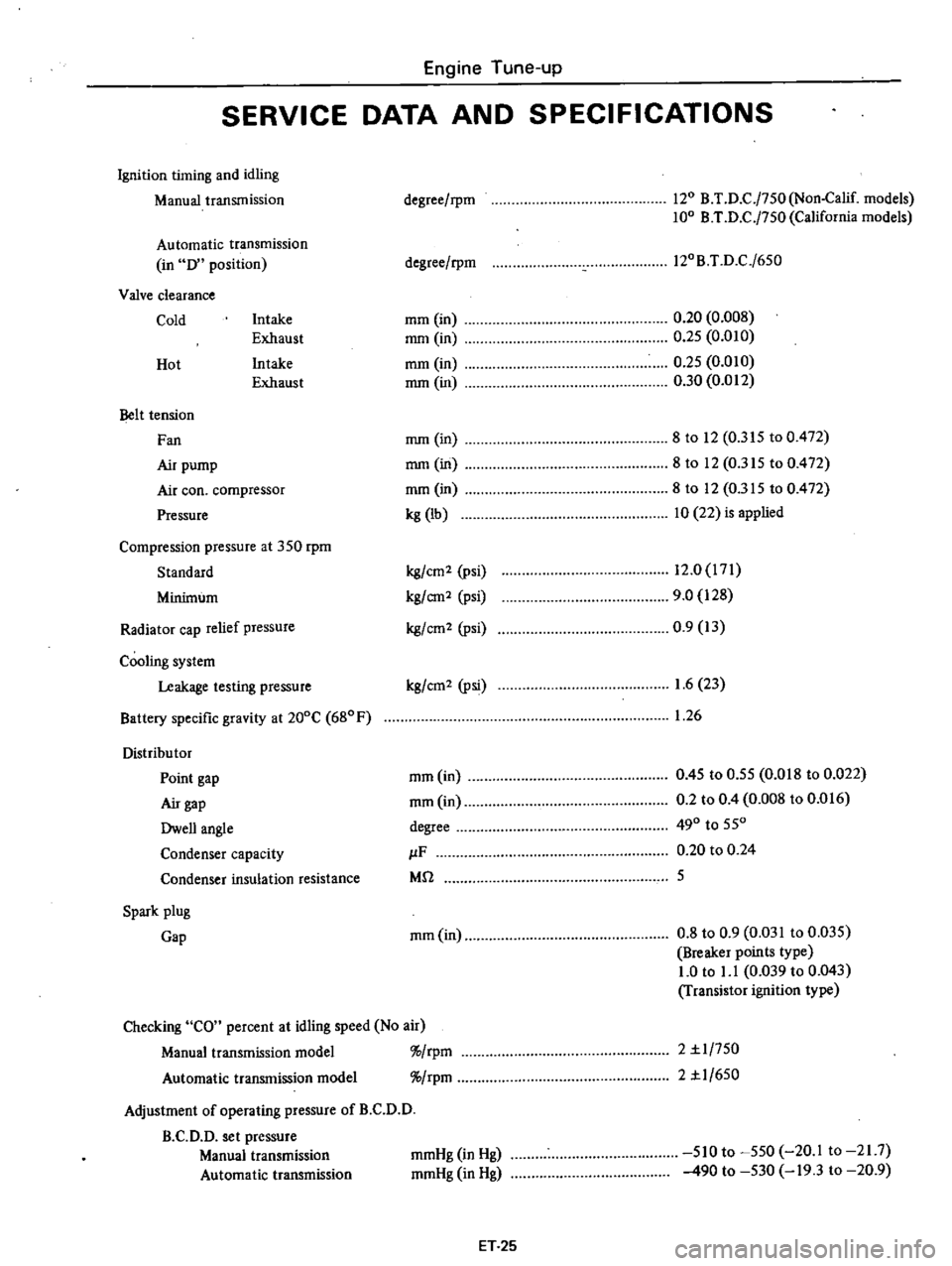
SERVICE
DATA
AND
SPECIFICATIONS
Ignition
timing
and
idling
Manual
transmission
Automatic
transmission
in
D
position
Valve
clearance
Cold
Intake
Exhaust
Intake
Exhaust
Hot
Belt
tension
Fan
Air
pump
Air
coo
compressor
Pressure
Compression
pressure
at
350
rpm
Standard
Minimum
Radiator
cap
relief
pressure
Cooling
system
Leakage
testing
pressure
Battery
specific
gravity
at
200C
680F
Distribu
tor
Point
gap
Air
gap
Dwell
angle
Condenser
capacity
Condenser
insulation
resistance
Spark
plug
Gap
degree
rpm
120
B
T
D
C
j750
Non
Calif
models
100
B
T
D
C
j750
California
models
degree
rpm
l20B
T
D
C
j650
mm
in
mm
in
mm
in
mm
in
0
20
0
008
0
25
0
010
0
25
0
010
0
30
0
012
mm
in
mm
in
mm
in
kg
lb
8
to
12
0
315
to
0
472
8to
12
0
315
to
0
472
8
to
12
0
315
to
0
472
10
22
is
applied
kg
cm2
psi
kg
em2
psi
kg
em
2
psi
12
0
171
9
0
128
0
9
13
kg
cm2
Psi
1
6
23
1
26
mm
in
mm
in
degree
IF
Mil
0
45
to
0
55
0
018
to
0
022
0
2
to
0
4
0
008
to
0
016
490
to
550
0
20
to
0
24
5
mm
in
0
8
to
0
9
0
031
to
0
035
Breaker
points
type
1
0
to
1
1
0
039
to
0
043
Transistor
ignition
type
Checking
CO
percent
at
idling
speed
No
air
Manual
transmission
model
rpm
Automatic
transmission
model
rpm
Adjustment
of
operating
pressure
of
B
C
D
D
B
C
D
D
set
pressure
Manual
transmission
Automatic
transmission
2
1
1
750
2
1
1
650
mmHg
in
Hg
mmHg
in
Hg
510
to
550
20
1
to
21
7
490
to
530
19
3
to
20
9
ET
25
Page 46 of 537
DATSUN
PICK
UP
MODEL
620
SERIES
lMlSSAN
I
oJ
NISSAN
MOTOR
CO
LTD
TOKYO
JAPAN
SECTION
EM
ENGINE
MECHANICAL
GENERAL
DESCRIPTION
ENGINE
DISASSEMBLY
INSPECTION
AND
REPAIR
ENGINE
ASSEMBLY
SERVICE
DATA
AND
SPECIFICATIONS
TROUBLE
DIAGNOSES
AND
CORRECTIONS
SPECIAL
SERVICE
TOOLS
EM
2
EM
4
EM
8
EM
21
EM
2l
EM
31
EM
33
Page 55 of 537
rr
ROCKER
ARM
AND
VALVE
ROCKER
PIVOT
Check
pivot
head
and
cam
contact
and
pivot
contact
surfaces
of
rocker
arm
for
damage
or
wear
If
damage
is
found
replace
them
A
faulty
pivot
must
be
replaced
together
with
its
corresponding
rocker
arm
VALVE
GUIDE
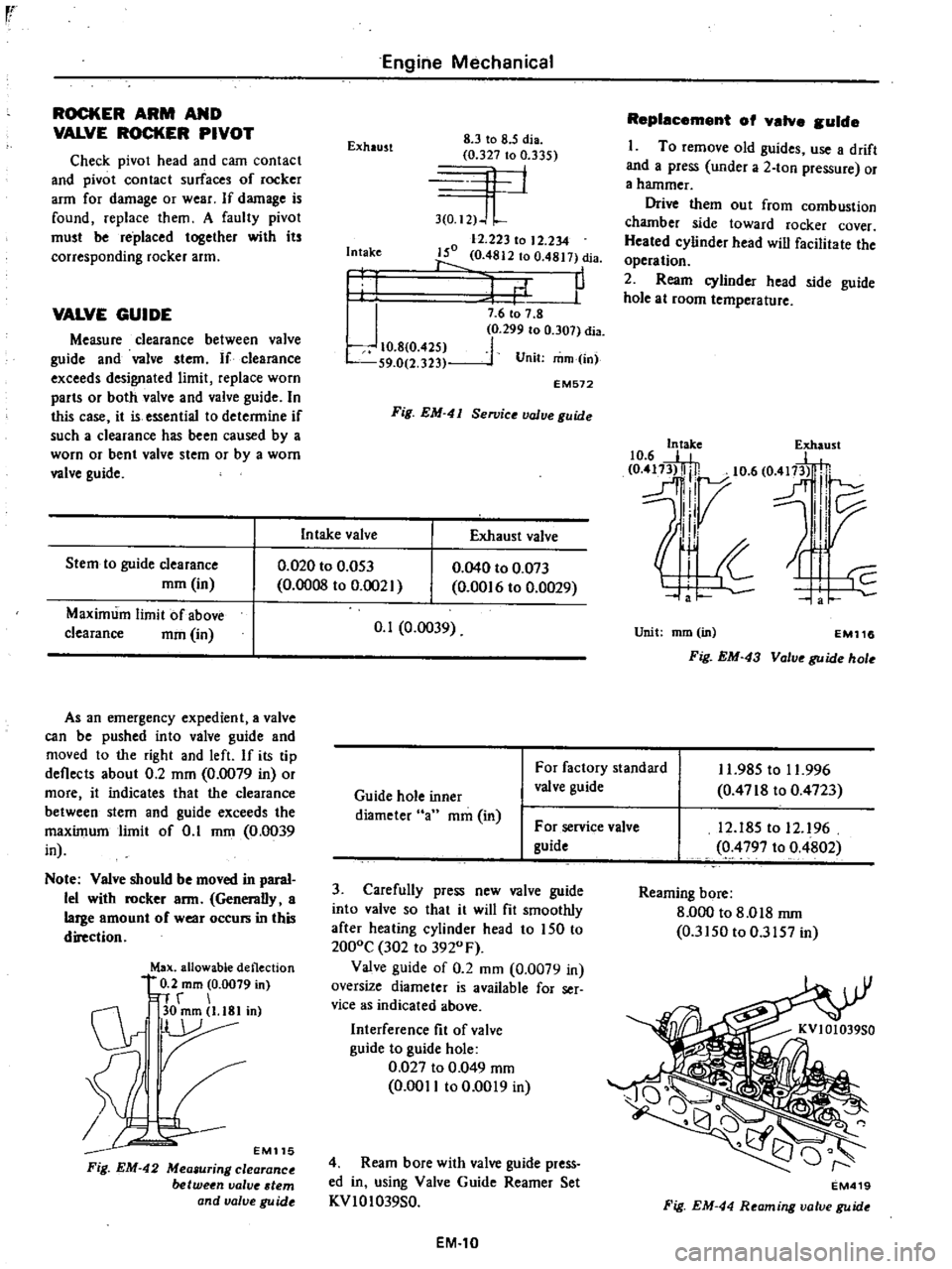
Measure
clearance
between
valve
guide
and
valve
stem
If
clearance
exceeds
designated
limit
replace
worn
parts
or
both
valve
and
valve
guide
In
this
case
it
is
essential
to
determine
if
such
a
clearance
has
been
caused
by
a
worn
or
bent
valve
stem
or
by
a
worn
valve
guide
Stem
to
guide
clearance
mm
in
Maximum
limit
of
above
clearance
mm
in
Engine
Mechanical
Exhaust
8
3
to
8
5
dia
0
327
to
0
335
4
1
3
0
I2
J
L
12
223
to
12
234
150
0
4812
to
0
4817
dia
1
P
Intake
I
I
J
10
8
0
425
S9
0
2
323
7
6
to
7
8
0
299
to
0
307
dia
1
Unit
mm
in
EM572
Fig
EM
41
Se11Jice
value
guide
In
take
valve
Exhaust
valve
0
020
to
0
053
0
0008
to
0
002
As
an
emergency
expedient
a
valve
can
be
pushed
into
valve
guide
and
moved
to
the
right
and
left
If
its
tip
deflects
about
0
2
mm
0
0079
in
or
more
it
indicates
that
the
clearance
between
stem
and
guide
exceeds
the
maximum
limit
of
0
1
mm
0
0039
in
Note
Valve
should
be
moved
in
paral
lel
with
rocker
arm
Generally
a
large
amount
of
wear
occurs
in
this
direction
Max
allowable
deflection
0
2
mm
0
0079
in
n
r
C1r
30mm
l
18Iin
r
EM115
Fig
EM
42
Mea
uring
clearance
between
valve
tern
and
valve
gu
ide
0
040
to
0
073
0
00
6
to
0
0029
0
1
0
0039
Replacement
of
valve
guide
I
To
remove
old
guides
use
a
drift
and
a
press
under
a
2
ton
pressure
or
a
hammer
Drive
them
out
from
combustion
chamber
side
toward
rocker
cover
Heated
cylinder
head
will
facilitate
the
operation
2
Ream
cylinder
head
side
guide
hole
at
room
temperature
10
6
E
e
417
5t
0
m3l
lj
10
6
O
fl
H
dl7
l
IV
II
Unit
mm
in
EM116
Fig
EM
43
Valve
guide
hole
Guide
hole
inner
diameter
an
mm
in
For
factory
standard
valve
guide
11
985
to
11
996
0
4718
to
0
4723
For
service
valve
guide
3
Carefully
press
new
valve
guide
into
valve
so
that
it
will
fit
smoothly
after
heating
cylinder
head
to
150
to
2000C
302
to
3920
F
Valve
guide
of
0
2
mm
0
0079
in
oversize
diameter
is
available
for
ser
vice
as
indicated
above
Interference
fit
of
valve
guide
to
guide
hole
0
027
to
0
049
mm
0
0011
to
0
0019
in
4
Ream
bore
with
valve
guide
press
ed
in
using
Valve
Guide
Reamer
Set
KVIOI039S0
EM
10
12
185
to
12
96
0
4797
to
0
4802
Reaming
bore
8
000
to
8
018
rnm
0
3150
to
0
3157
in
EM419
Fig
EM
44
Reaming
valve
guide
Page 56 of 537
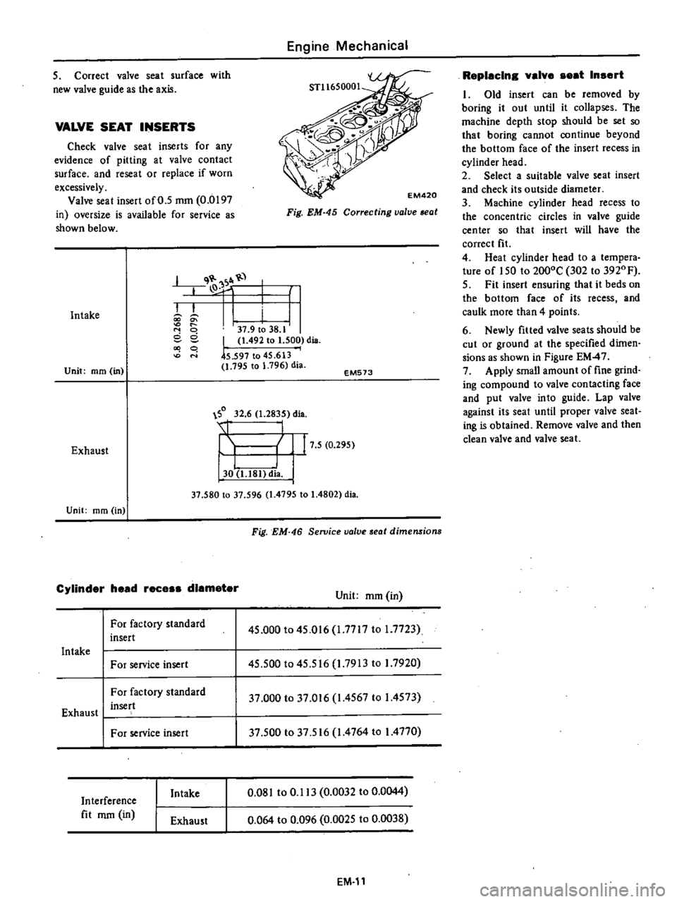
q
1
I
k
k
lO
i
I
37
9
to
38
1
eel
1
492
to
1
500
dis
co
q
0
45
597
to
45
613
1
795
to
1
796
dia
5
Correct
valve
seat
surface
with
new
valve
guide
as
the
axis
VALVE
SEAT
INSERTS
Check
valve
seat
inserts
for
any
evidence
of
pitting
at
valve
contact
surface
and
reseat
or
replace
if
worn
excessively
Valve
seat
insert
of
0
5
mm
0
0197
in
oversize
is
available
for
service
as
shown
below
Intake
Unit
mm
in
Engine
Mechanical
Fig
EM
45
Correcting
valve
seat
EM573
0
32
6
1
2835
dia
Exhaust
I
I
30
U81
dia
17
5
0
295
Unit
mm
in
37
580
to
37
596
1
4795
to
1
4802
dia
Cylinder
head
rece
diameter
For
factory
standard
insert
Intake
For
service
insert
For
factory
standard
insert
Exhaust
I
For
service
insert
Interference
fit
mm
in
Intake
Exhaust
Fig
EM
46
Seroice
valve
seat
dimensions
Unit
mm
in
45
000
to
45
016
1
7717
to
1
7723
45
500
to
45
516
1
7913
to
I
7920
37
000
to
37
016
1
4567
to
I
4573
37
500
to
37
516
1
4764
to
I
4770
0
081
to
0
113
0
0032
to
0
0044
0
064
to
0
096
0
0025
to
0
0038
EM
11
Replacln
valve
eat
In
ert
1
Old
insert
can
be
removed
by
boring
it
out
until
it
collapses
The
machine
depth
stop
should
be
set
so
that
boring
cannot
continue
beyond
the
bottom
face
of
the
insert
recess
in
cylinder
head
2
Select
a
suitable
valve
seat
insert
and
check
its
outside
diameter
3
Machine
cylinder
head
recess
to
the
concentric
circles
in
valve
guide
center
so
that
insert
will
have
the
correct
fit
4
Heat
cylinder
head
to
a
tempera
ture
of
150
to
2000C
302
to
3920
F
5
Fit
insert
ensuring
that
it
beds
on
the
bottom
face
of
its
recess
and
caulk
more
than
4
points
6
Newly
fitted
valve
seats
should
be
cut
or
ground
at
the
specified
dimen
sions
as
shown
in
Figure
EM
47
7
Apply
small
amount
of
fine
grind
ing
compound
to
valve
contacting
face
and
put
valve
into
guide
Lap
valve
against
its
seat
until
proper
valve
seat
ing
is
obtained
Remove
valve
and
then
clean
valve
and
valve
sea
1
Page 72 of 537
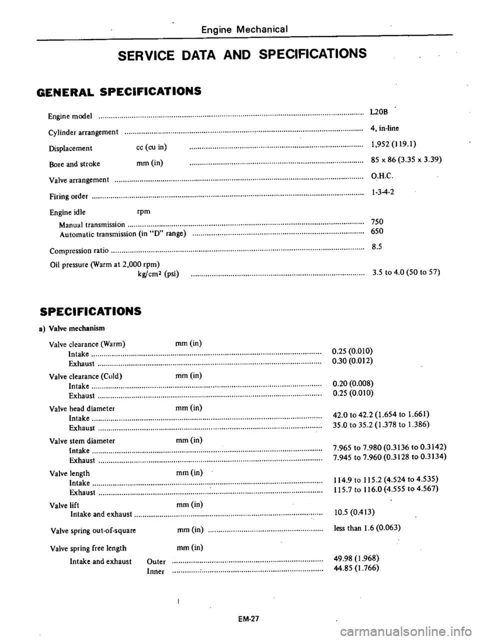
Engine
Mechanical
SERVICE
DATA
AND
SPECIFICATIONS
GENERAL
SPECIFICATIONS
Engine
model
L20B
Cylinder
arrangement
Displacemen
t
Bore
and
stroke
4
in
line
cc
co
in
mm
in
1
952
J
19
1
85
x
86
3
35
x
3
39
O
H
C
I
3
4
2
Valve
arrangement
Firing
order
Engine
idle
rpm
Manual
transmission
Automatic
transmission
in
D
range
750
650
8
5
Compression
ratio
Oil
pressure
Warm
at
2
000
rpm
kg
cm2
psi
3
5
to
4
0
50
to
57
SPECIFICATIONS
a
Valve
mechanism
Valve
clearance
Warm
Intake
Exhaust
Valve
clearance
Cold
Intake
Exhaust
Valve
head
diameter
Intake
Exhaust
Valve
stem
diameter
Intake
Exhaust
Valve
length
Intake
Exhaust
Valve
lift
Intake
and
exhaust
mm
in
0
25
0
010
0
30
0
012
mmOn
0
20
0
008
0
25
0
010
mm
in
42
0
to
42
2
1
654
to
1
661
35
0
to
35
2
1
378
to
1
386
mm
in
7
965
to
7
980
0
3136
to
0
3142
7
945
to
7
960
0
3128
to
0
3134
mmOn
114
9
to
115
2
4
524
to
4
535
115
7
to
116
0
4
555
to
4
567
mmOn
Valve
spring
out
of
square
mm
in
10
5
0
413
less
than
1
6
0
063
Valve
spring
free
length
mm
in
Intake
and
exhaust
Outer
Inner
49
98
1
968
44
85
J
766
EM
27