wheel bolts DATSUN PICK-UP 1977 User Guide
[x] Cancel search | Manufacturer: DATSUN, Model Year: 1977, Model line: PICK-UP, Model: DATSUN PICK-UP 1977Pages: 537, PDF Size: 35.48 MB
Page 359 of 537
UPPER
AND
LOWER
LINKS
REMOVAL
AND
INSTALLATION
Removal
I
Raise
vehicle
on
a
hoist
or
stands
2
Remove
wheel
and
brake
drum
as
an
assembly
3
Remove
wheel
hub
Refer
to
see
tion
Front
Axle
4
Loosen
bolts
retaining
brake
disc
to
knuckle
spindle
and
remove
brake
disc
5
Remove
knuckle
arm
torsion
bar
spimgJ
stabilizer
shock
absorber
and
tension
rod
in
t
ili
order
referring
the
related
sections
6
Remove
upper
fulcrum
bolt
se
curing
knuckle
spindle
support
to
upper
link
assembly
and
disassemble
them
7
Remove
upper
link
bushings
from
knuckle
spindle
support
8
Remove
screw
bushings
from
both
ends
of
lower
link
fulcrum
pin
9
Loosen
nut
at
lower
portion
of
knuckle
spindle
support
from
inside
and
pull
out
cotter
pin
retaining
ful
crum
pin
10
Pull
out
fulcrum
pin
with
drift
and
remove
knuckle
spindle
support
with
knuckle
spindle
from
lower
link
Then
detach
dust
cover
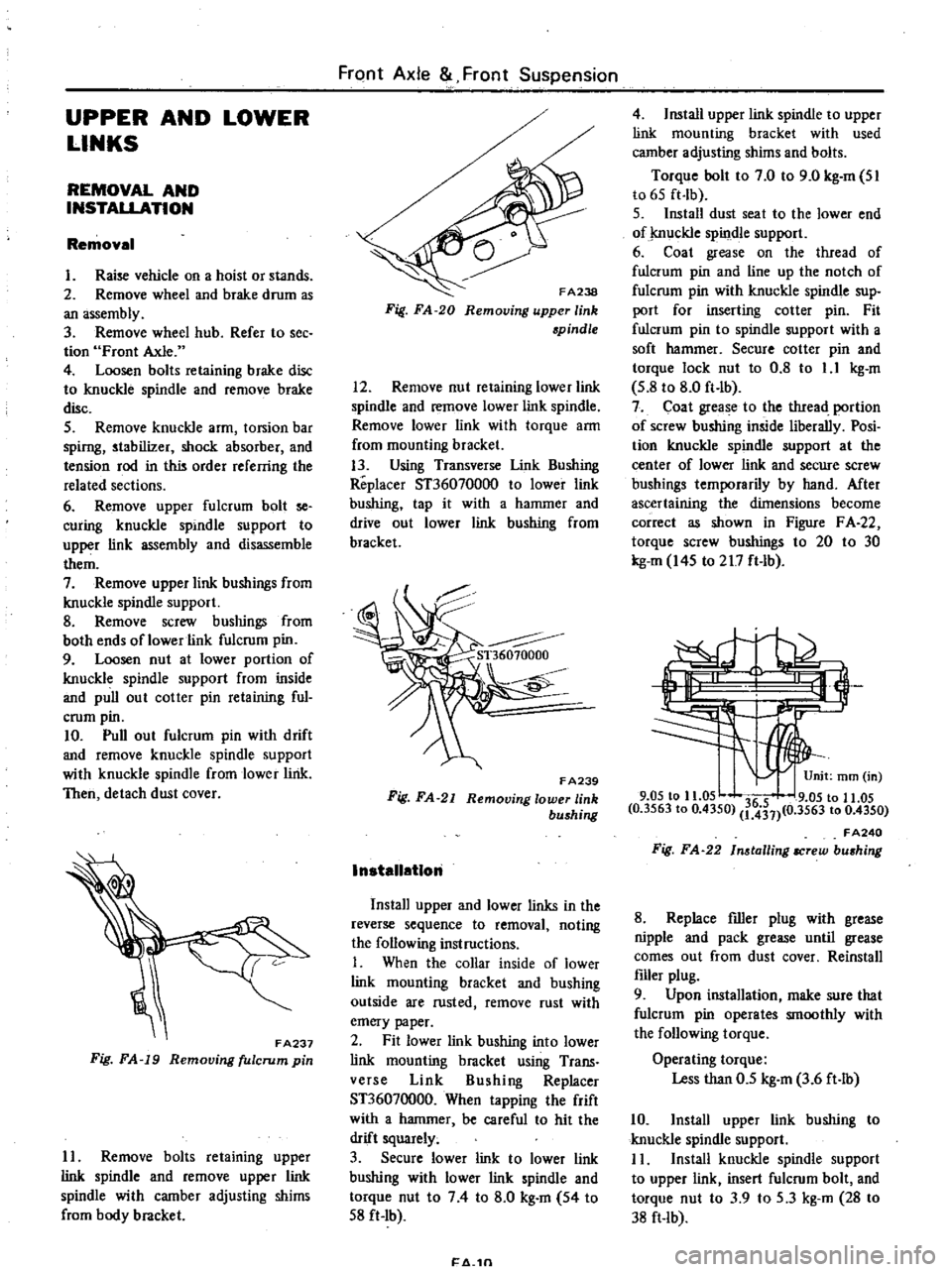
FA237
Fig
FA
19
Removing
fulcrum
pin
II
Remove
bolts
retaining
upper
link
spindle
and
remove
upper
link
spindle
with
camber
adjusting
shims
from
body
bracket
FrClnt
Axle
Front
Suspension
FA238
Fig
FA
20
Removing
upper
link
spindle
12
Remove
nut
retaining
lower
link
spindle
and
remove
lower
link
spindle
Remove
lower
link
with
torque
arm
from
mounting
bracket
13
Using
Transverse
Unk
Bushing
Replacer
ST36070000
to
lower
link
bushing
tap
it
with
a
hammer
and
drive
out
lower
link
bushing
from
bracket
F
A239
Fig
FA
21
Removing
lower
link
bushing
InstallatIon
Install
upper
and
lower
links
in
the
reverse
sequence
to
removal
noting
the
following
instructions
I
When
the
collar
inside
of
lower
link
mounting
bracket
and
bushing
outside
are
rusted
remove
rust
with
emery
paper
2
Fit
lower
link
bushing
into
lower
link
mounting
bracket
using
Trans
verse
Link
Bushing
Replacer
ST36070000
When
tapping
the
frift
with
a
hammer
be
careful
to
hit
the
drift
squarely
3
Secure
lower
link
to
lower
link
bushing
with
lower
link
spindle
and
torque
nut
to
74
to
8
0
kg
m
54
to
S8
ft
Ib
1
4
1n
4
Install
upper
link
spindle
to
upper
link
mounting
bracket
with
used
camber
adjusting
shims
and
bolts
Torque
bolt
to
7
0
to
9
0
kg
m
SI
to
6S
ft
lb
S
Install
dust
seat
to
the
lower
end
of
j
nuckle
spindle
support
6
Coat
grease
on
the
thread
of
fulcrum
pin
and
line
up
the
notch
of
fulcrum
pin
with
knuckle
spindle
sup
port
for
inserting
cotter
pin
Fit
fulcrum
pin
to
spindle
support
with
a
soft
hammer
Secure
cotter
pin
and
torque
lock
nut
to
0
8
to
1
1
kg
m
S
8
to
8
0
ft
lb
7
Coat
grease
to
the
tIuead
portion
of
screw
bushing
inside
liberally
Posi
tion
knuckle
spindle
support
at
the
center
of
lower
link
and
secure
screw
bushings
temporarily
by
hand
Mter
ascertaining
the
dimensions
become
correct
as
shown
in
Figure
F
A
22
torque
screw
bushings
to
20
to
30
kg
m
I4S
to
217
ft
lb
3
9
05
to
11
05
36
5
9
05
to
11
05
0
3563
to
0
4350
1
431
0
3563
to
0
4350
FA240
Fig
FA
22
In
tailing
IICrew
bu
hing
8
Replace
filler
plug
with
grease
nipple
and
pack
grease
until
grease
comes
out
from
dust
cover
Reinstall
filler
plug
9
Upon
installation
make
sure
that
fulcrum
pin
operates
smoothly
with
the
following
torque
Operating
torque
Less
than
0
5
kg
m
3
6
ft
lb
10
Install
upper
link
bushing
to
knuckle
spindle
support
I
I
Install
knuckle
spindle
support
to
upper
link
insert
fulcrum
bolt
and
torque
nut
to
3
9
to
S
3
kg
m
28
to
38
ft
lb
Page 365 of 537
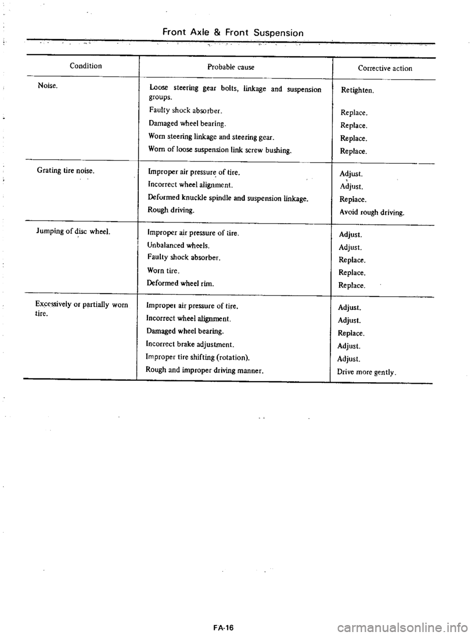
Condition
Noise
Grating
tire
noise
Jumping
of
disc
wheeL
Excessively
or
partially
worn
tire
Front
Axle
Front
Suspension
Probable
cause
Loose
steering
gear
bolts
linkage
and
suspension
groups
Faulty
shock
absorber
Damaged
wheel
bearing
Worn
steering
linkage
and
steering
gear
Worn
of
loose
suspension
link
screw
bushing
Improper
air
pressure
of
lire
Incorrect
wheel
alignment
Deformed
knuckle
spindle
and
suspension
linkage
Rough
driving
Improper
air
pressure
of
tire
Unbalanced
wheels
Faulty
shock
absorber
Worn
tire
Deformed
wheel
rim
Improper
air
pressure
of
tire
Incorrect
wheel
alignment
Damaged
wheel
bearing
Incorrect
brake
adjustment
Improper
tire
shifting
rotation
Rough
and
improper
wiving
manner
FA
16
Corrective
action
Retighten
Replace
Replace
Replace
Replace
Adjust
Adjust
Replace
Avoid
rough
driving
Adjust
Adjust
Replace
Replace
Replace
Adjust
Adjust
Replace
Adjust
Adjust
Drive
more
gently
Page 369 of 537
DESCRIPTION
The
rear
axle
assembly
is
of
the
semi
floating
type
in
which
the
vehicle
weight
is
carried
on
the
axle
shafts
through
bearings
enclosed
in
the
bear
ing
cages
on
outer
rear
axle
case
The
axle
case
is
a
pressed
steeJ
Banjo
type
housing
The
rear
axle
assembly
is
attached
to
the
frame
through
semi
elliptic
leaf
springs
and
telescopic
hydraulic
shock
absorbers
Rubber
bushings
at
either
end
of
the
leaf
springs
and
shock
absorbers
are
designed
to
absorb
vibra
tion
and
noise
The
rear
axle
shaft
splines
engage
the
differential
side
gears
with
a
float
ing
fit
The
outer
ends
are
supported
in
the
bearing
cages
by
tapered
roller
bearings
The
bearings
are
lubricated
by
wheel
bearing
grease
The
axle
shaft
oil
seals
are
located
outboard
and
inboard
of
the
bearing
The
bearings
are
se
cured
against
shoulders
on
the
shafts
by
press
fit
and
held
in
place
by
a
large
nuts
The
bearing
cages
hold
the
bearings
against
shoulders
on
the
axle
case
Whee
side
thrust
is
taken
at
the
wheel
bearings
through
the
thrust
block
so
an
axle
shaft
may
be
re
moved
simply
by
removing
the
bolts
holding
the
brake
disc
to
the
bearing
cage
and
the
rear
axle
case
REMOVAL
AND
INSTALLATION
REAR
AXLE
ASSEMBLY
It
is
not
necessary
to
remove
the
reaT
axle
assembly
for
any
normal
repairs
However
if
the
axle
case
is
dam
aged
the
rear
axle
assembly
may
be
removed
and
installed
using
the
fol
lowing
procedures
I
Raise
rear
of
vehicle
high
enough
to
permi
t
working
underneath
Place
a
jack
under
center
of
axle
case
so
it
just
starts
to
raise
rear
axle
assembly
Place
stands
solidly
under
frame
members
on
both
sides
Remove
rear
wheels
Rear
Axle
Rear
Suspension
2
Mark
relationship
across
propeller
shaft
flange
and
companion
flange
of
differential
carrier
so
that
the
original
combination
is
restored
at
assembly
3
Remove
bolts
retaining
center
bearing
bracket
and
connecting
shaft
to
companion
flange
Withdraw
pro
peller
shaft
sleeve
yoke
from
transmis
sion
by
moving
the
shaft
rearward
passing
it
under
rear
axle
4
Disconnect
rear
hand
brake
cable
Q
by
removing
adjusting
nut
@
three
clamps
ID
and
connector
@
Slide
front
cable
rearward
and
discon
nect
rear
cable
@
at
connector
ID
by
removing
three
clamps
ID
5
Disconnect
rear
brake
hose
at
frame
@
Cover
brake
hose
and
pipe
openings
to
prevent
entrance
of
dirt
6
Disconnect
shock
absorbers
at
lower
end
f
and
push
shock
ab
sorbers
up
out
of
the
way
7
Lower
jack
under
axle
case
Re
move
U
bolts
spring
clips
@
to
separate
axle
case
from
spring
8
Place
a
jack
under
center
of
axle
case
Pass
axle
case
through
space
above
spring
and
take
it
out
to
the
side
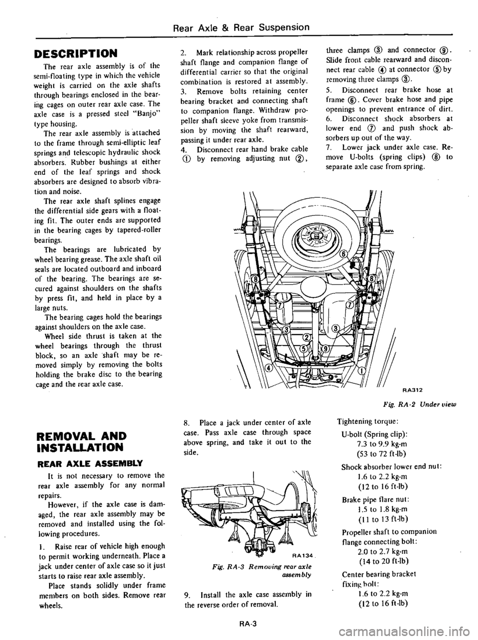
RA134
Fig
RA
3
Removing
rear
axle
assembly
9
Install
the
axle
case
assembly
in
the
reverse
order
of
removal
RA
3
RA312
Fig
RA
2
Under
view
Tightening
torque
U
bolt
Spring
clip
7
3
to
9
9
kg
m
53
to
72
ft
lb
Shock
absorber
lower
end
nut
1
6
to
2
2
kg
m
12to
16ft
Ib
Brake
pipe
flare
nut
I
S
to
1
8
kg
m
II
to
13
ft
Ib
Propeller
shaft
to
companion
flange
connecting
bolt
2
0
to
2
7
kg
m
14
to
20
ft
Ib
Center
bearing
bracket
fixin
holt
1
6
to
2
2
kg
m
12
to
16
ft
Ib
Page 370 of 537

REAR
AXLE
SHAFT
AND
WHEEL
BEARING
I
Raise
rear
of
vehicle
and
support
under
axle
case
on
stands
Remove
rear
wheel
2
Disconnect
rear
hand
brake
cable
by
removing
adjusting
nut
and
clamps
3
Disconnect
brake
tube
at
rear
wheel
cylinder
Cover
brake
tube
and
wheel
cylinder
openings
to
prevent
entrance
of
dirt
4
Remove
brake
drum
Not
If
brake
drum
cannot
be
easily
removed
return
brake
adjuster
install
two
bolts
M8
x
I
2S
in
holes
on
the
flange
face
of
brake
drum
and
tighten
bolts
evenly
until
brake
drum
is
driven
out
5
Remove
nuts
retaining
wheel
bearing
cage
to
brake
disc
I
Jq
AA135
Fig
RA
4
Removing
nuts
AA418
Fig
RA
5
Removing
rear
axle
shaft
assem
bly
7
Remove
oil
seal
in
axle
case
if
necessary
and
install
new
seal
Insure
against
damaging
the
seal
lip
Rear
Axle
Rear
Suspension
8
Position
axle
shaft
in
vise
with
Rear
Axle
Stand
ST07630000
9
Unbend
lock
washer
with
a
screw
driver
Note
Do
not
use
used
lock
washer
again
RAl38
Fig
RA
6
Unbending
lock
washer
10
Remove
lock
nut
using
Rear
Axle
Bearing
Lock
Nut
Wrench
ST38020000
I
AA139
Fig
RA
7
R
mouing
lock
nut
II
Withdraw
wheel
bearing
to
gether
with
bearing
cage
and
brake
disc
using
Rear
Axle
Shaft
Bearing
Puller
HT72480000
HT72480000
r
t
Rvr
G
l
AA343
Fig
RA
8
Removing
bearing
o
12
Remove
oil
seal
in
bearing
cage
if
necessary
13
To
remove
wheel
bearing
outer
race
after
removed
oil
seal
apply
a
brass
drift
to
race
side
surface
and
withdraw
it
by
tapping
the
lop
of
drift
with
a
hammer
Installing
can
be
proceeded
in
the
reverse
order
of
removal
procedure
as
follows
RA
4
I
Fit
wheel
bearing
outer
race
by
tapping
with
a
brass
hammer
evenly
while
fitting
2
Install
a
new
oil
seal
in
bearing
cage
Lubricate
cavity
between
seal
lips
with
wheel
bearing
grease
after
fitting
seal
3
Place
bearing
cage
with
brake
disc
and
bearing
spacer
on
axle
shaft
and
fit
bearing
cone
To
install
bearing
cone
apply
a
brass
drift
to
race
side
surface
and
tapping
the
top
of
drift
with
a
hammer
AA141
Fig
RA
9
Installing
whetl
bearing
4
Place
bearing
lock
washer
Q
and
bearing
nut
lock
washer
@
on
axle
shaft
and
tighten
lock
nut
@
using
Rear
AJde
Bearing
Lock
Nut
Wrench
ST38020000
and
bend
up
lock
wash
er
Notes
a
Be
careful
to
place
the
faced
side
of
nut
to
washer
side
so
that
washer
is
not
damaged
b
Coincide
washer
lip
with
nut
groove
correc
ly
by
tightening
nul
and
bend
washer
carefuljy
so
that
lip
will
nol
be
damaged
Tightening
torque
IS
to
20
kg
m
J08
to
14S
ft
Ib
t
i
i
f
ifii
itf
L
4
S
11
iI
i
j
pu
y
J
t
Mf
i
I
AA142
Fig
RA
IO
Layout
of
ock
nut
Page 371 of 537
S
Apply
wheel
bearing
grease
in
wheel
bearing
and
recess
of
axle
case
end
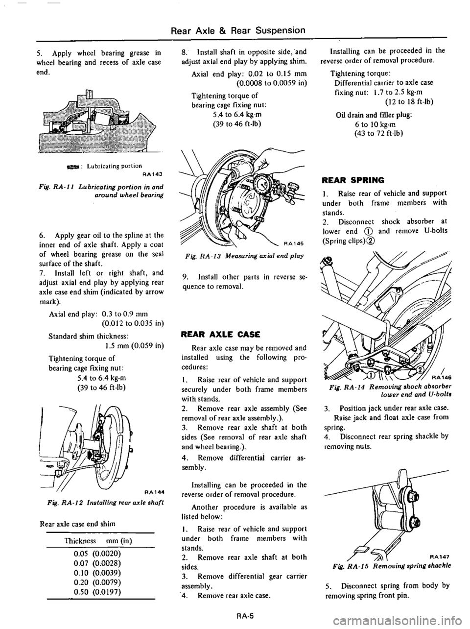
Lubricating
portion
AA143
Fig
RA
l1
Lubricating
portion
in
and
around
wheel
bearing
6
Apply
gear
oil
to
the
spline
at
the
inner
end
of
axle
shaft
Apply
a
coal
of
wheel
bearing
grease
on
the
seal
surface
of
the
shaft
7
Install
left
or
right
shaft
and
adjust
axial
end
play
by
applying
rear
axle
case
end
shim
indicated
by
arrow
mark
Axial
end
play
0
3
to
0
9
mOl
0
012
to
0
035
in
Standard
shim
thickness
1
5
mm
0
059
in
Tightening
torque
of
bearing
cage
fIXing
nut
54
to
6
4
kg
m
39
to
46
ft
lb
w
AA144
Fig
RA
12
Installing
rear
axle
shaft
Rear
axle
case
end
shim
Thickness
mOl
in
O
OS
0
0020
0
07
0
0028
0
10
0
0039
0
20
0
0079
O
SO
0
0197
Rear
Axle
Rear
Suspension
8
Install
shaft
in
opposite
side
and
adjust
axial
end
play
by
applying
shim
Axial
end
play
0
02
to
O
IS
mOl
0
0008
to
0
0059
in
Tightening
torque
of
bearing
cage
fixing
nut
5
4
to
6
4
kg
m
39
to
46
ft
Ib
Fig
RA
13
Measuring
axial
end
play
9
Install
other
parts
in
reverse
se
quence
to
removal
REAR
AXLE
CASE
Rear
axle
case
may
be
removed
and
installed
using
the
following
pro
cedures
I
Raise
rear
of
vehicle
and
support
securely
under
both
frame
members
with
stands
2
Remove
rear
axle
assembly
See
removal
of
rear
axle
assembly
3
Remove
rear
axle
shaft
at
both
sides
See
removal
of
rear
axle
shaft
and
wheel
bearing
4
Remove
differentiai
carrier
as
sembly
Installing
can
be
proceeded
in
the
reverse
order
of
removal
procedure
Another
procedure
is
available
as
listed
below
I
Raise
rear
of
vehicle
and
support
under
both
frame
members
with
stands
2
Remove
ear
axle
shaft
at
both
sides
3
Remove
differential
gear
carrier
assembly
4
Remove
rear
axle
case
RA
5
Installing
can
be
proceeded
in
the
reverse
order
of
removal
procedure
Tightening
torque
Differential
carrier
to
axle
case
fixing
nut
I
7
to
2
5
kg
m
12
to
18
ft
Ib
Oil
drain
and
fIller
plug
6
to
10
kg
m
43
to
72
ft
lb
REAR
SPRING
1
Raise
rear
of
vehicle
and
support
under
both
frame
members
with
stands
2
Disconnect
shock
absorber
at
lower
end
CD
and
remove
U
bolts
Spring
clips
2
3
Position
jack
under
rear
axle
case
Raise
jack
and
float
axle
case
from
spring
4
Disconnect
rear
spring
shackle
by
removing
nuts
AA147
Fig
RA
15
Removing
spring
shackle
5
Disconnect
spring
from
body
by
removing
spring
front
pin
Page 372 of 537
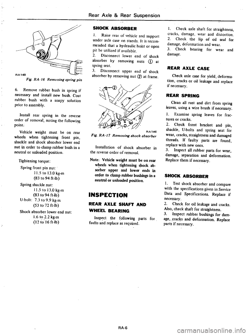
RA148
Fig
RA
16
Remvoing
spring
pin
6
Remove
rubber
bush
in
spring
if
necessary
and
install
new
bush
Coat
rubber
hush
with
a
soapy
solution
prior
to
assembly
InstaH
rear
spring
in
the
reverse
order
of
removal
noting
the
following
poinc
Vehicle
weight
must
be
on
rear
wheels
when
tightening
front
pin
shackle
and
shock
absorber
lower
end
nut
in
order
to
clamp
rubber
bush
in
a
neutral
or
unloaded
position
Tightening
torque
Spring
fTont
pin
nut
11
5
to
13
0
kg
m
83
to
94
ft
Ib
Spring
shackle
nut
11
5
to
13
0
kg
m
83
t094
ft
b
U
bolt
7
3
to
9
9
kg
m
S3
to
72
ft
lb
Shock
absorber
lower
end
nut
1
6
to
2
2
kg
m
12
to
16
ft
lb
Rear
Axle
Rear
Suspension
SHOCK
ABSORBER
Raise
rear
of
vehicle
and
support
under
axle
case
on
stands
It
is
recom
mended
that
a
hydraulic
hoist
or
open
pit
be
utilized
if
available
2
Disconnect
lower
end
of
shock
absorber
by
removing
nuts
Q
at
spring
seat
3
Disconnect
upper
end
of
shock
absorber
by
removing
nut
2
at
frame
RA146
Fig
RA
J
7
Removing
shock
absorber
Installation
of
shock
absorber
in
the
reverse
order
of
removal
Note
Vehicle
weight
must
be
on
Tear
wheels
when
tigtrtening
shock
ab
sorber
upper
and
lower
ends
in
order
to
clamp
rubber
bushings
in
a
neutral
or
unloaded
position
INSPECTION
REAR
AXLE
SHAFT
AND
WHEEL
BEARING
Inspect
the
following
parts
for
faults
and
replace
as
required
RA
6
I
Check
axle
shaft
for
straightness
cracks
damage
wear
and
distortion
2
Check
the
lip
of
oil
seal
for
damage
deformation
and
wear
3
Check
bearing
for
wear
and
damage
REAR
AXLE
CASE
Check
axle
case
for
yield
deforma
tion
cracks
or
oil
leakage
and
replace
if
necessary
REAR
SPRING
Clean
all
rust
and
dirt
from
spring
leaves
using
a
wire
brush
if
necessary
1
Examine
spring
leaves
for
frae
tures
or
cracks
2
Check
front
bracket
and
pin
shackle
U
bolts
and
spring
seat
for
wear
cracks
straightness
and
damaged
threads
If
faulty
parts
are
found
replace
with
new
ones
3
Inspect
all
rubber
parts
for
wear
damage
separation
and
deformation
Replace
them
if
necessary
SHOCK
ABSORBER
I
Test
shock
absorber
and
compare
with
the
specifications
given
in
Service
Data
and
Specifications
Replace
if
necessary
2
Check
for
oil
leakage
and
cracks
Also
check
shaft
for
straightness
3
Inspect
rubber
bushings
for
dam
age
cracl
s
and
deformation
Replace
parts
if
necessary
Page 374 of 537
Rear
Axle
Rear
Suspension
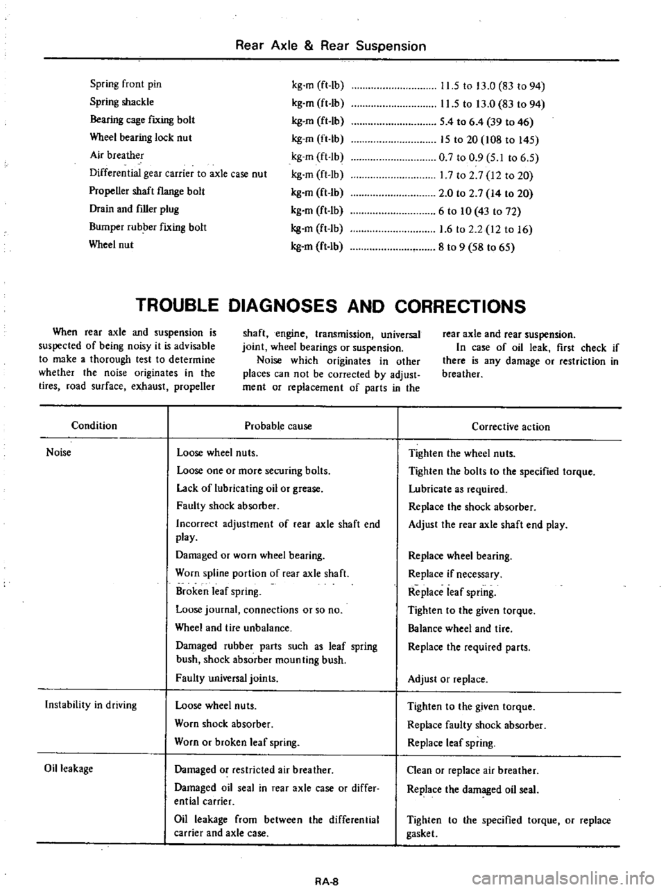
Spring
front
pin
Spring
shackle
Bearing
cage
fIXing
bolt
Wheel
bearing
lock
nut
Air
breather
Differential
gear
carrier
to
axle
case
nut
Propeller
shaft
flange
bolt
Drain
and
filler
plug
Bumper
rubber
fixing
bolt
Wheel
nut
kg
m
ft
lb
kg
m
ft
Ib
kg
en
ft
lb
kg
m
ft
Ib
kg
m
ft
Ib
kg
m
ft
Ib
kg
en
ft
Ib
kg
m
ft
Ib
kg
m
ft
Ib
kg
m
ft
lb
11
5
to
13
0
83
to
94
11
5
to
13
0
83
to
94
S
4
to
6
4
39
to
46
IS
to
20
108
to
l4S
0
7
to
0
9
S
I
to
6
S
17
to
2
7
12
to
20
2
0
to
2
7
14
to
20
6
to
10
43
to
72
1
6
to
2
2
12
to
16
8
to
9
S8
to
6S
TROUBLE
DIAGNOSES
AND
CORRECTIONS
When
rear
axle
and
suspension
is
suspected
of
being
noisy
it
is
advisable
to
make
a
thorough
test
to
determine
whether
the
noise
originates
in
the
tires
road
surface
exhaust
propeller
shaft
engine
transmission
universal
joint
wheel
bearings
or
suspension
Noise
which
originates
in
other
places
can
not
be
corrected
by
adjust
ment
or
replacement
of
parts
in
the
rear
axle
and
rear
suspension
In
case
of
oil
leak
first
check
if
there
is
any
damage
or
restriction
in
breather
Condition
Probable
cause
Noise
Loose
wheel
nuts
Loose
one
or
more
securing
bolts
Lack
of
lubricating
oil
or
grease
Faulty
shock
absorber
Incorrect
adjustment
of
rear
axle
shaft
end
play
Damaged
or
worn
wheel
bearing
Worn
spline
portion
of
rear
axle
shaft
Broken
leaf
spring
Loose
journal
connections
or
so
no
Wheel
and
tire
unbalance
Damaged
rubber
parts
such
as
leaf
spring
bush
shock
absorber
moun
ting
bush
Faulty
universal
joints
Instability
in
driving
Loose
wheel
nuts
Worn
shock
absorber
Worn
or
broken
leaf
spring
Oil
leakage
Damaged
or
restricted
air
breather
Damaged
oil
seal
in
rear
axle
case
or
differ
ential
carrier
Oil
leakage
from
between
the
differential
carrier
and
axle
case
RA
8
Corrective
action
Tighten
the
wheel
nuts
Tighten
the
bolts
to
the
specified
torque
Lubricate
as
required
Replace
the
shock
absorber
Adjust
the
rear
axle
shaft
end
play
Replace
wheel
bearing
Replace
if
necessary
Replace
leaf
spring
Tighten
to
the
given
torque
Balance
wheel
and
tire
Replace
the
required
parts
Adjust
or
replace
Tighten
to
the
given
torque
Replace
faulty
shock
absorber
Replace
leaf
spring
Clean
or
replace
air
breather
Replace
the
damaged
oil
seal
Tighten
to
the
specified
torque
or
replace
gasket
Page 385 of 537
Ibove
mentioned
st
is
available
when
op
the
FRONT
BRAKE
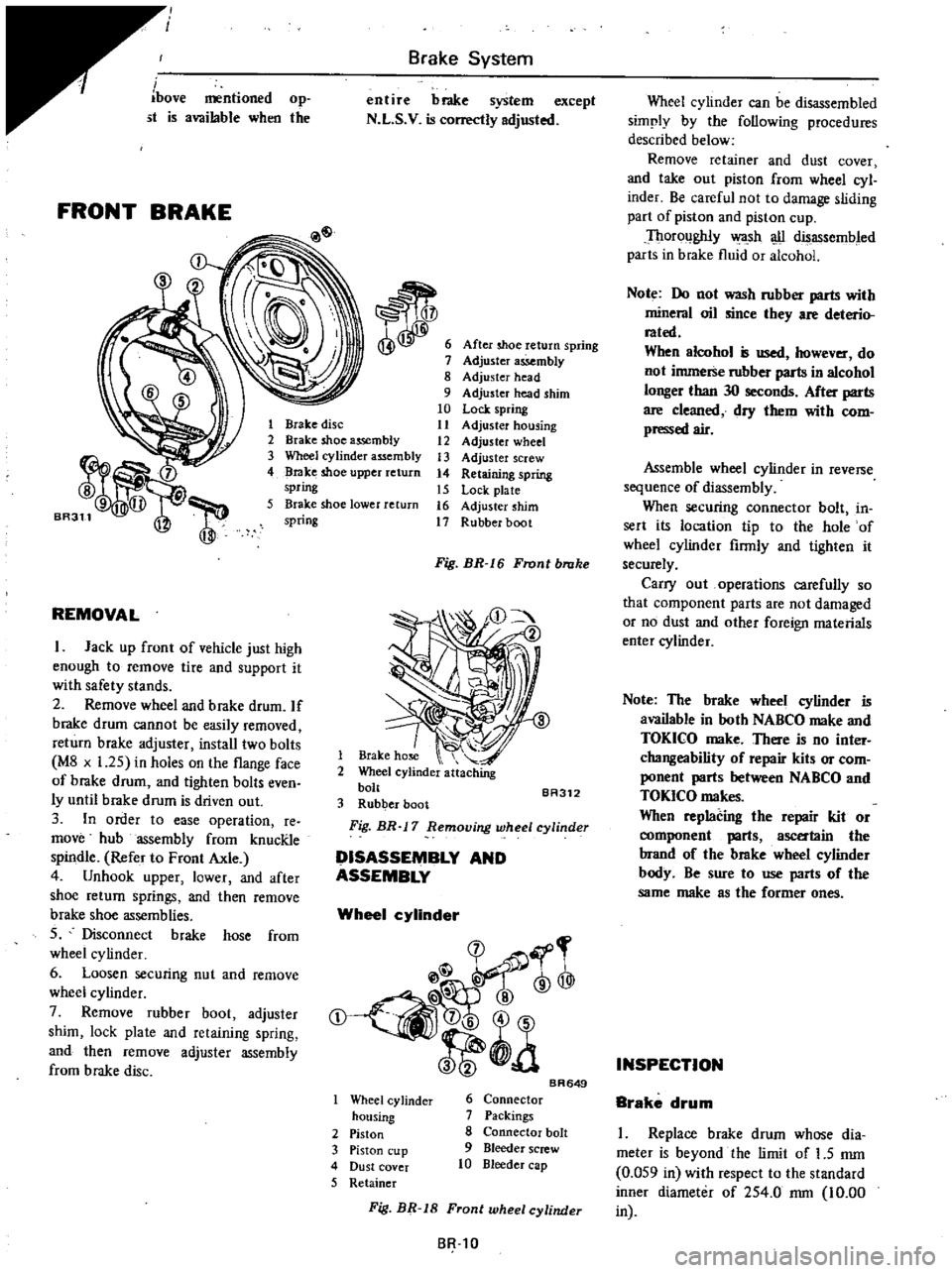
Brake
System
entire
brake
system
except
N
L
S
V
is
correctly
adjusted
After
shoe
return
spring
Adjuster
assembly
8
Adjuster
head
9
Adjuster
head
shim
10
Lock
spring
11
Adjuster
housing
12
Adjuster
wheel
13
Adjuster
screw
14
Retaining
spring
15
Lock
plate
16
Adjuster
shim
17
Rubber
boot
1
Brake
disc
2
Brake
shoe
assembly
3
Wheel
cylinder
assembly
4
Brake
shoe
upper
return
spring
5
Brake
shoe
lower
return
spring
REMOVAL
I
Jack
up
front
of
vehicle
just
high
enough
to
remove
tire
and
support
it
with
safety
stands
2
Remove
wheel
and
brake
drum
If
brake
drum
cannot
be
easily
removed
return
brake
adjuster
install
two
bolts
M8
x
1
25
in
holes
on
the
flange
face
of
brake
drum
and
tighten
bolts
even
ly
until
brake
drum
is
driven
out
3
In
order
to
ease
operation
re
move
hub
assembly
from
knucRle
spindle
Refer
to
Front
Axle
4
Unhook
upper
lower
and
after
shoe
return
springs
and
then
remove
brake
shoe
assemblies
S
Disconnect
brake
hose
from
wheel
cy
linder
6
Loosen
securing
nut
and
remove
wheel
cylinder
7
Remove
rubber
boot
adjuster
shim
lock
plate
and
retaining
spring
and
then
remove
adjuster
assembly
from
brake
disc
Fig
BR
I
6
Front
brake
1
Brake
hose
2
Wheel
cylinder
attaching
bolt
BA312
3
Rubber
boot
Fig
BR
17
Removing
wheel
cylinder
DISASSEMBLY
AND
ASSEMBLY
Wheel
cylinder
@
rr
l
@
t
a
Wheel
cy
linder
housing
2
Piston
3
Piston
cup
4
Dust
cover
5
Retainer
BR649
6
Connector
7
Packings
8
Connector
bolt
9
Bleeder
screw
10
Bleeder
cap
Wheel
cylinder
can
be
disassembled
simply
by
the
following
procedures
described
below
Remove
retainer
and
dust
cover
and
take
out
piston
from
wheel
cyl
inder
Be
careful
not
to
damage
sliding
part
of
piston
and
piston
cup
Thoroughly
wa
sh
u
disassembled
parts
in
brake
fluid
or
alcohol
Note
Do
not
wash
rubber
parts
with
mineral
oil
since
they
are
deterio
rated
When
alcohol
is
used
however
do
not
immerse
rubber
parts
in
alcohol
longer
than
30
seconds
After
parts
are
cleaned
dry
them
with
com
pressed
air
Assemble
wheel
cylinder
in
reverse
sequence
of
diassembly
When
securing
connector
bolt
in
sert
its
location
tip
to
the
hole
of
wheel
cylinder
firmly
and
tighten
it
securely
Carry
out
operations
carefully
so
that
component
parts
are
not
damaged
or
no
dust
and
other
foreign
materials
enter
cylinder
Note
The
brake
wheel
cylinder
is
available
in
both
NABCO
make
and
TOKICO
make
There
is
no
inter
changeability
of
repair
kits
or
com
ponent
parts
between
NABCO
and
TOKICO
makes
When
replacing
the
repair
kit
or
ent
parts
ascertain
the
brand
of
the
brake
wheel
cylinder
body
Be
sure
to
use
parts
of
the
same
make
as
the
former
ones
INSPECTION
Brake
drum
I
Replace
brake
drum
whose
dia
meter
is
beyond
the
limit
of
1
5
mm
0
OS9
in
with
respect
to
the
standard
inner
diameter
of
2S4
0
rom
10
00
SR
tO
Fig
BR
18
Front
wheel
cylinder
in
Page 398 of 537

Condition
Brake
chatters
Brake
squeals
Pedal
pulsates
Brakes
fade
Brakes
drag
Unbalanced
brakes
Brake
System
Probable
cause
Groove
or
out
of
round
brake
drum
Loose
or
bent
brake
disc
Distorted
brake
shoes
or
pads
Grease
or
brake
fluid
on
linings
Dirty
or
scored
brake
drums
Distorted
brake
shoes
or
bent
support
plate
Weak
or
broken
brake
shoe
retaining
spring
or
return
spring
Glazed
or
contaminated
brake
lining
Out
of
round
or
off
center
drum
Brake
fluid
has
too
low
boiling
point
Use
of
improper
linings
or
brake
linings
are
contaminated
Brake
drums
are
out
of
round
Hydraulic
connections
master
cylinder
and
wheel
cylinders
are
corroded
or
damaged
Bleed
screw
is
open
Pedal
linkage
is
binding
or
push
rod
adjust
ment
is
too
long
Master
cylinder
compensator
part
is
ob
structed
Seized
master
cylinder
piston
Poor
shoe
condition
Poor
wheel
cylinder
condition
Deformation
of
piston
cups
Hand
brake
will
not
return
Clogged
master
cylinder
return
port
Improper
tire
inflation
Improper
adjustment
of
shoe
to
drum
clear
anee
Grease
oil
mud
or
water
on
linings
or
pads
Mud
in
brake
drum
Deterioration
of
linings
or
pads
Excessive
wear
of
linings
or
pads
BR
23
Corrective
action
Grind
or
replace
as
required
Tighten
support
plate
bolts
to
specified
torque
or
replace
plate
Replace
as
necessary
Replace
linings
Blowout
assembly
with
compressed
air
or
refinish
drum
Replace
faulty
unit
Replace
if
faulty
Cam
ground
lining
to
eliminate
glaze
If
it
doesn
t
replace
linings
Turn
drum
or
replace
as
necessary
Drain
and
fill
system
with
approved
fluid
Replace
linings
Repair
or
replace
as
necessary
Repair
as
necessary
Close
screw
and
bleed
system
Lubricate
linkage
check
pedal
return
spring
for
condition
and
adjust
push
rod
as
neces
sary
Blowout
foreign
matter
with
compressed
air
Disassemble
master
cylinder
and
replace
piston
Bleed
system
Clean
and
repair
Repair
or
replace
Replace
Check
and
repair
Clean
Inflate
to
correct
pressure
Readjust
Clean
brake
mechanism
and
check
for
cause
of
problem
Replace
linings
or
pads
Clean
Replace
Replace
Page 399 of 537

Condition
Pedal
yields
under
slight
pressure
Brake
System
Probable
cause
Wheel
cylinder
in
poor
condition
Poor
sliding
condition
of
brake
shoe
Looseness
of
cylinder
body
or
back
plate
securing
bolts
Scored
or
out
of
round
drums
Sticking
wheel
cylinder
cups
Deformation
of
back
plate
Incorrect
adjustment
of
wheel
bearings
Incorrect
adjustment
of
wheel
alignment
Looseness
of
leaf
spring
securing
U
bolts
Faulty
N
L
S
V
Deteriorated
check
valve
Ex
ternalleaks
Leakage
on
master
cylinder
BR
24
Corrective
action
Repair
or
replace
Adjust
Fasten
or
replace
Recondition
or
replace
brake
drum
as
reo
quired
Check
for
improper
lining
contact
with
drum
and
grind
lining
if
necessary
Recondition
or
replace
cylinder
Replace
Adjust
or
replace
Adjust
Tighten
or
replace
Replace
Replace
check
valve
and
bleed
system
Check
master
cylinder
piping
and
wheel
cylinder
for
leaks
and
repair
Overhaul
master
cylinder