steering DATSUN PICK-UP 1977 Owner's Manual
[x] Cancel search | Manufacturer: DATSUN, Model Year: 1977, Model line: PICK-UP, Model: DATSUN PICK-UP 1977Pages: 537, PDF Size: 35.48 MB
Page 412 of 537
I
J
L6
3
4
5
1
Apply
recommended
grease
to
screw
bushing
interior
plain
bushing
interior
dust
seal
inside
and
bushing
sliding
surface
of
idler
ann
Screw
bushing
tightening
torque
12
kg
m
87
ft
lb
2
Before
installing
idler
arm
assem
bly
replace
f
iller
plug
with
grease
nipple
and
apply
recommended
grease
to
idler
ann
through
this
grease
nipple
until
grease
is
forced
out
at
the
lower
end
of
the
dust
seal
lip
Remove
grease
I
8
I
II
I
I
FIODt
Inspection
and
repair
Ball
joint
1
When
ball
stud
is
worn
or
axial
play
is
too
excessive
replace
cross
rod
socket
or
side
rod
with
a
new
one
2
When
dust
cover
is
broken
or
defonned
be
sure
to
replace
with
a
new
one
Axial
end
play
0
1
to
0
5
mm
0
004
to
0
020
in
Initial
swing
torque
S
to
15
kg
cm
70
to
209
in
oz
STEERING
SYSTEM
nipple
and
reinstall
filler
plug
3
In
installing
idler
arm
assembly
make
sure
that
the
standard
dimension
A
is
adjusted
correctly
Standard
dimension
A
137
8
to
139
8
mm
S
42S
to
S
504
in
See
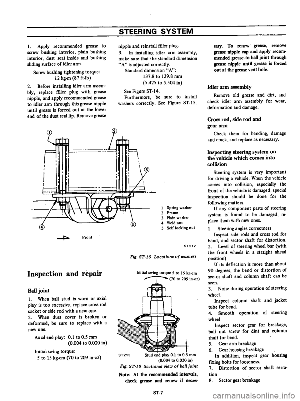
Figure
ST
14
Furthermore
be
sure
to
install
washers
correctly
See
Figure
ST
IS
Spring
washer
Frame
Plain
washer
Weld
nut
Self
locking
nut
ST212
Fig
ST
15
Locations
of
washers
Initial
swing
torque
5
to
15
kg
cm
70
to
209
in
oz
ST213
ST
7
sary
To
renew
grease
remove
grease
nipple
cap
and
apply
recom
mended
grease
to
ball
joint
through
grease
nipple
until
grease
is
forced
out
at
the
grease
vent
hole
Idler
arm
3B8embly
Remove
old
grease
and
dirt
and
check
idler
ann
assembly
for
wear
deformation
and
damage
CrOBS
rod
side
rod
and
gear
arm
Check
them
for
bending
damage
and
crack
and
replace
as
necessary
Inspecting
steering
system
on
the
vehicle
which
comes
into
collision
Steering
system
is
very
important
for
driving
a
vehicle
When
the
vehicle
comes
into
collision
especially
the
front
of
the
vehicle
is
damaged
special
inspection
should
be
done
for
the
following
matters
If
any
component
parts
of
steering
system
is
found
to
be
damaged
re
place
them
with
new
ones
1
Steering
angles
correctness
Inspect
side
rods
and
cross
rod
for
bend
and
sector
shaft
for
distortion
2
Level
of
steering
wheel
bar
with
the
front
wheels
in
a
straight
ahead
position
If
its
deflection
is
more
than
about
90
degrees
the
bend
or
distortion
of
sector
shaft
and
column
shaft
can
be
seen
3
Noise
during
operation
of
steering
wheel
Inspect
column
shaft
and
jacket
tube
for
bend
4
Smooth
operation
of
steering
wheel
Inspect
sector
gear
for
breakage
ball
nut
screw
for
dint
and
column
shaft
for
bend
S
Gear
arm
breakage
6
Gear
housing
breakage
In
addition
inspect
gear
housing
f
IXing
bolts
for
looseness
7
Distortion
of
sector
shaft
serra
tion
8
Sector
gear
breakage
Page 413 of 537
STEERING
SYSTEM
9
Column
shaft
breakage
on
the
welded
section
In
addition
inspect
column
shaft
for
scratch
10
Deformation
of
body
construc
tion
and
frame
Inspect
the
installation
portion
of
steering
system
on
the
body
construe
tion
and
frame
for
deformation
or
any
other
faulty
conditions
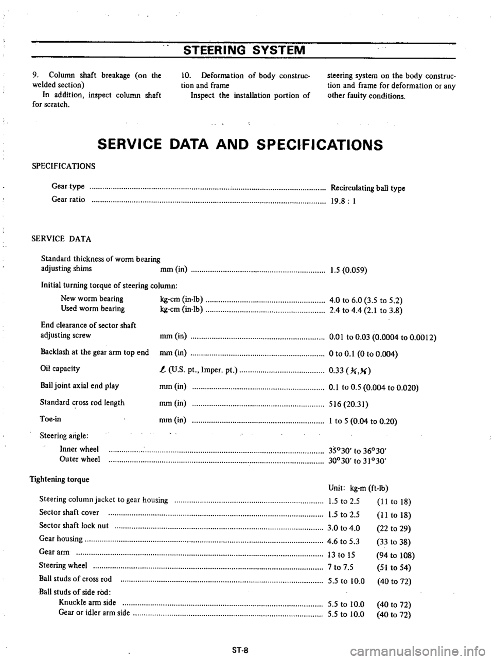
SERVICE
DATA
AND
SPECIFICATIONS
SPECIFICA
nONS
Gear
type
Gear
ratio
SERVICE
DATA
Standard
thickness
of
worm
bearing
adjusting
shims
mOl
in
Initial
turning
torque
of
steering
column
New
worm
bearing
kg
em
in
lb
Used
worm
bearing
kg
em
in
lb
End
clearance
of
sector
shaft
adjusting
screw
rom
in
Backlash
at
the
gear
arm
top
end
rom
in
Oil
capacity
t
U
S
pt
Impel
pt
Bail
joint
axial
end
play
rom
in
Standard
cross
rod
length
rom
in
Toe
in
rom
in
Steering
arigle
Inner
wheel
Outer
wheel
Tightening
torque
Steering
column
jacket
to
gear
housing
Sector
shaft
cover
Sector
shaft
lock
nut
Gear
housing
Gear
arm
Steering
wheel
Bail
studs
of
cross
rod
Ball
studs
of
side
roo
Knuckle
arm
side
Gear
or
idler
arm
side
ST
8
Recirculating
ball
type
19
8
I
1
5
0
OS9
4
0
to
6
0
3
5
to
S
2
2
4
to
4
4
2
1
to
3
8
om
to
0
03
0
0004
to
0
0012
o
to
0
1
0
to
0
004
0
33
J
X
0
1
to
0
5
0
004
to
0
020
516
20
31
I
to
S
0
04
to
0
20
35030
to
36030
30030
to
31030
Unit
kg
m
ft
lb
1
5
to
2
S
II
to
18
I
S
to
2
S
I
I
to
18
3
0
to
4
0
22
to
29
4
6
to
5
3
33
to
38
13
to
IS
94
to
108
7
to
7
S
SI
to
S4
S
S
to
10
0
40
to
72
S
S
to
10
0
S
5
to
10
0
40
to
72
40
to
72
Page 414 of 537
STEERING
SYSTEM
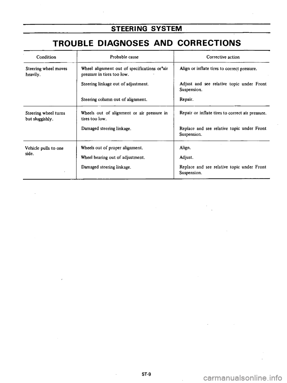
TROUBLE
DIAGNOSES
AND
CORRECTIONS
Condition
Steering
wheel
moves
heavily
Steering
wheel
turns
but
sluggishly
Vehicle
pulls
to
one
side
Probable
cause
Wheel
alignment
out
of
specifications
or
air
pressure
in
tires
too
low
Steering
linkage
out
of
adjustment
Steering
column
out
of
alignment
Wheels
out
of
alignment
or
air
pressure
in
tires
too
low
Damaged
steering
linkage
Wheels
out
of
proper
alignment
Wheel
bearing
out
of
adjustment
Damaged
steering
linkage
ST
9
Corrective
action
Align
or
inflate
tires
to
correct
pressure
Adjust
and
see
relative
topic
under
Front
Suspension
Repair
Repair
or
inflate
tires
to
correct
air
pressure
Replace
and
see
relative
topic
under
Front
Suspension
Align
Adjust
Replace
and
see
relative
topic
under
Front
Suspension
Page 415 of 537
STEERING
SYSTEM
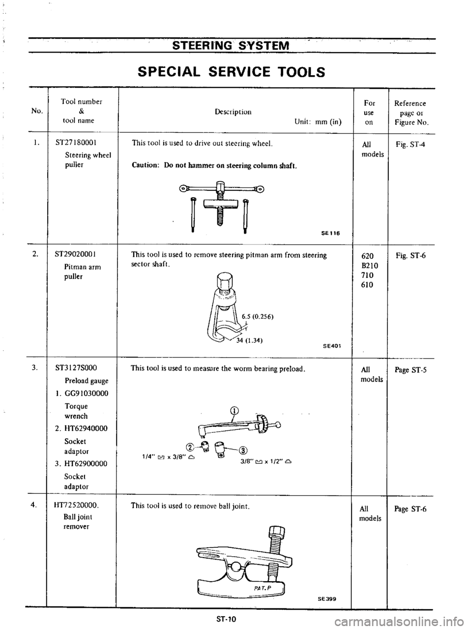
SPECIAL
SERVICE
TOOLS
No
Tool
number
tool
name
Description
Unit
mOl
in
For
use
on
Reference
page
or
Figure
No
ST27I80001
Steering
wheel
puller
This
tool
is
used
to
drive
out
steering
wheel
All
Fig
ST4
models
Caution
Do
not
hammer
on
steering
column
shaft
o
v
J
SE
116
2
ST29020001
Pitman
arm
puller
This
tool
is
used
to
remove
steering
pitman
arm
from
steering
sector
shaft
Fig
ST
6
SE401
3
ST3I
27S000
This
tool
is
used
to
measure
the
worm
bearing
preload
All
Page
ST
5
Preload
gauge
models
GG91030000
Torque
D
wrench
I
2
HT62940000
IJ
Socket
t
Y
ID
adaptor
114
3
8
Go
3
HT62900000
318
1
2
Socket
adaptor
4
HT72520000
This
tool
is
used
to
remove
ball
joint
All
Page
ST
6
Ball
joint
models
remover
620
B210
710
610
SE399
ST
10
Page 428 of 537
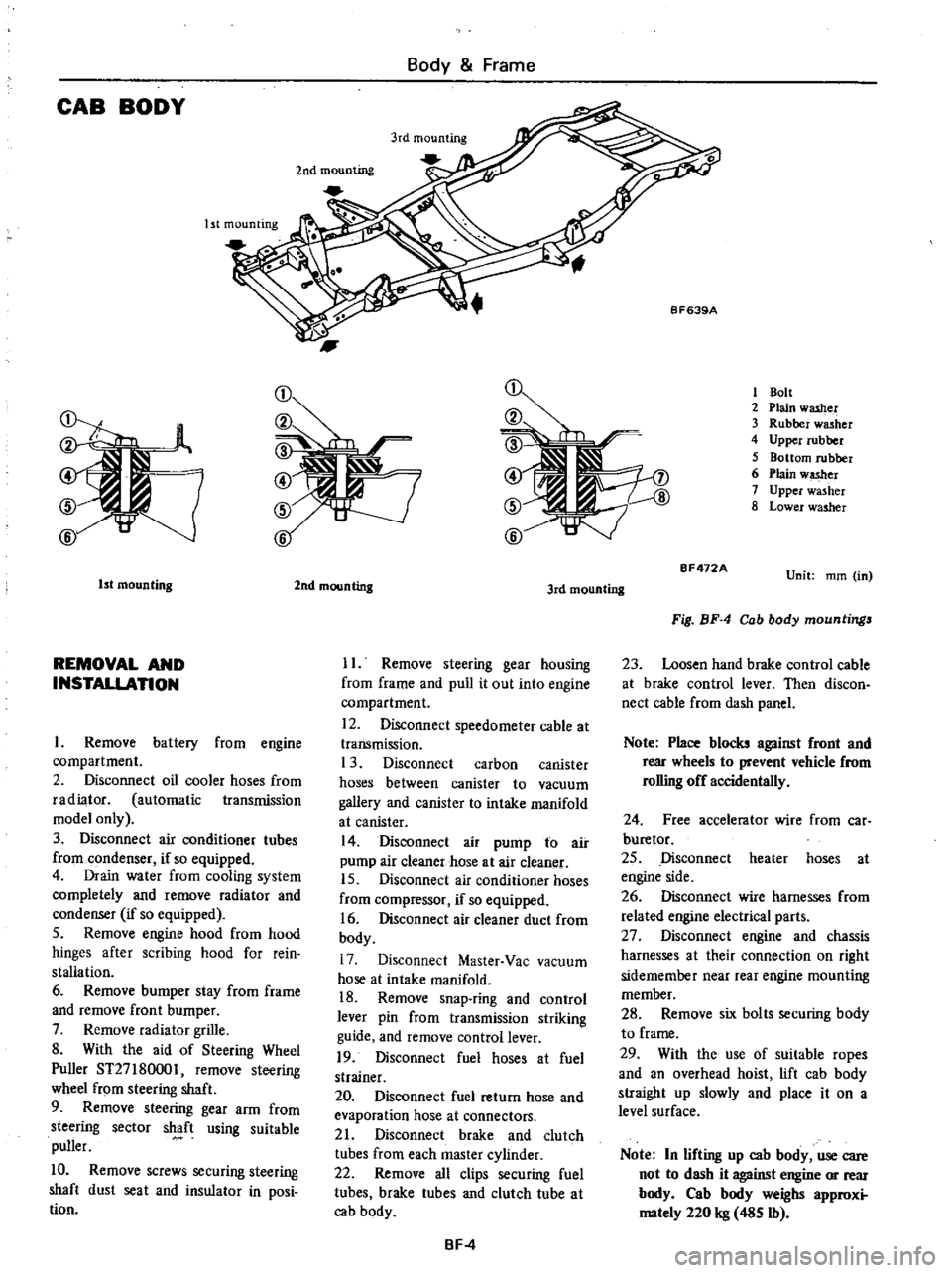
CAB
BODY
Body
Frame
Ist
mounting
2nd
mounting
1
Bolt
2
Plain
washer
3
Rubber
washer
4
Upper
rubber
5
Bottom
rubber
6
Plain
w
er
7
Upper
washer
8
Lower
washer
1st
mounting
REMOVAL
AND
INSTALLATION
Remove
battery
from
engine
compartment
2
Disconnect
oil
cooler
hoses
from
radiator
automatic
transmission
model
only
3
Disconnect
air
conditioner
tubes
from
condenser
if
so
equipped
4
Drain
water
from
cooling
system
completely
and
remove
radiator
and
condenser
if
so
equipped
5
Remove
engine
hood
from
hood
hinges
after
scribing
hood
for
rein
stallation
6
Remove
bumper
stay
from
frame
and
remove
front
bumper
7
Remove
radiator
grille
8
With
the
aid
of
Steering
Wheel
Puller
ST27
180001
remove
steering
wheel
from
steering
shaft
9
Remove
steering
gear
arm
from
steering
sector
shaft
using
suitable
puller
10
Remove
screws
securing
steering
shaft
dust
seat
and
insulator
in
posi
tion
2nd
mounting
3rd
mounting
II
Remove
steering
gear
housing
from
frame
and
pull
it
out
into
engine
compartment
12
Disconnect
speedometer
cable
at
transmission
1
3
Disconnect
carbon
canister
hoses
between
canister
to
vacuum
gallery
and
canister
to
intake
manifold
at
canister
14
Disconnect
air
pump
to
air
pump
air
cleaner
hose
at
air
cleaner
15
Disconnect
air
conditioner
hoses
from
compressor
if
so
equipped
16
Disconnect
air
cleaner
duct
from
body
17
Disconnect
Master
Vac
vacuum
hose
at
intake
manifold
18
Remove
snap
ring
and
control
lever
pin
from
transmission
striking
guide
and
remove
control
lever
19
Disconnect
fuel
hoses
at
fuel
strainer
20
Disconnect
fuel
return
hose
and
evaporation
hose
at
connectors
21
Disconnect
brake
and
clutch
tubes
from
each
master
cylinder
22
Remove
all
clips
securing
fuel
tubes
brake
tubes
and
clutch
tube
at
cab
body
BF
4
BF472A
Unit
mm
in
Fig
BF
4
Cab
body
mountings
23
Loosen
hand
brake
control
cable
at
brake
control
lever
Then
discon
nect
cable
from
dash
panel
Note
Place
blocks
against
front
and
rear
wheels
to
prevent
vehicle
from
rolling
off
accidentally
24
Free
accelerator
wire
from
car
buretor
25
Disconnect
heater
hoses
at
engine
side
26
Disconnect
wire
harnesses
from
related
engine
electrical
parts
27
Disconnect
engine
and
chassis
harnesses
at
their
connection
on
right
sidemember
near
rear
engine
mounting
member
28
Remove
six
bolts
securing
body
to
frame
29
With
the
use
of
suitable
ropes
and
an
overhead
hoist
lift
cab
body
straight
up
slowly
and
place
it
on
a
level
surface
Note
In
lifting
up
cab
body
use
care
not
to
dash
it
against
engine
or
rear
body
Cab
body
weighs
approxi
mately
220
kg
485
Ib
Page 441 of 537
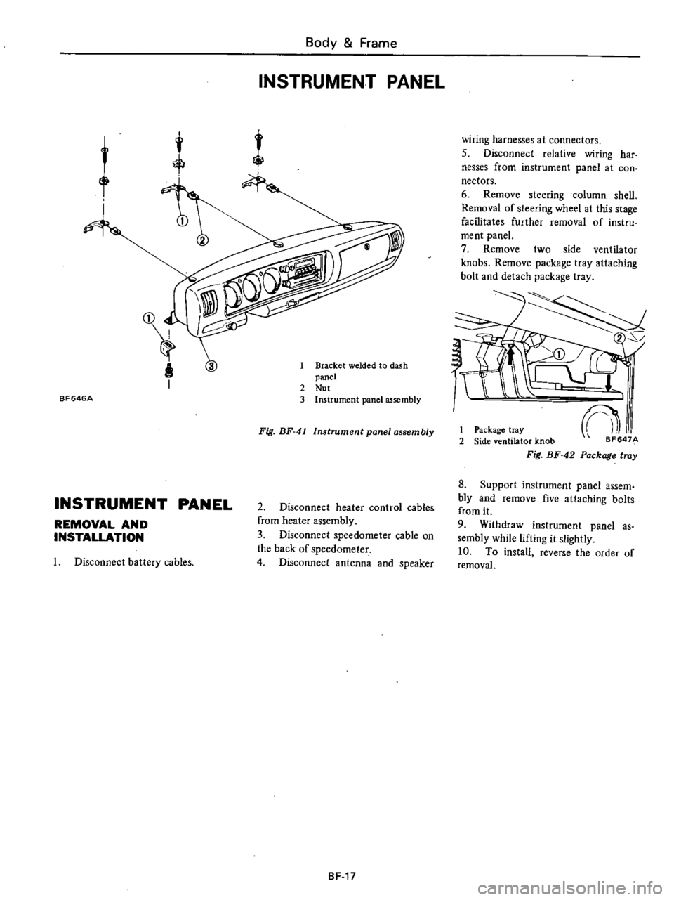
BF646A
Body
Frame
INSTRUMENT
PANEL
1
Bracket
welded
to
dash
panel
2
Nut
3
Instrument
panel
assembly
Fig
BF
41
Instrument
panel
assembly
INSTRUMENT
PANEL
REMOVAL
AND
INSTALLATION
2
Disconnect
heater
control
cables
from
heater
assembly
3
Disconnect
speedometer
cable
on
the
back
of
speedometer
4
Disconnect
antenna
and
speaker
Disconnect
battery
cables
8F
17
wiring
harnesses
at
connectors
5
Disconnect
relative
wiring
har
nesses
from
instrument
panel
at
con
nectors
6
Remove
steering
column
shell
Removal
of
steering
wheel
at
this
stage
facilitates
further
removal
of
instru
ment
panel
7
Remove
two
side
ventilator
knobs
Remove
package
tray
attaching
bolt
and
detach
package
tray
2
I
Package
tray
2
Side
ventilator
knob
Fig
BF
42
Package
tray
8
Support
instrument
panel
assem
bly
and
remove
five
attaching
bolts
from
it
9
Withdraw
instrument
panel
as
sembly
while
lifting
it
slightly
10
To
install
reverse
the
order
of
removal
Page 455 of 537
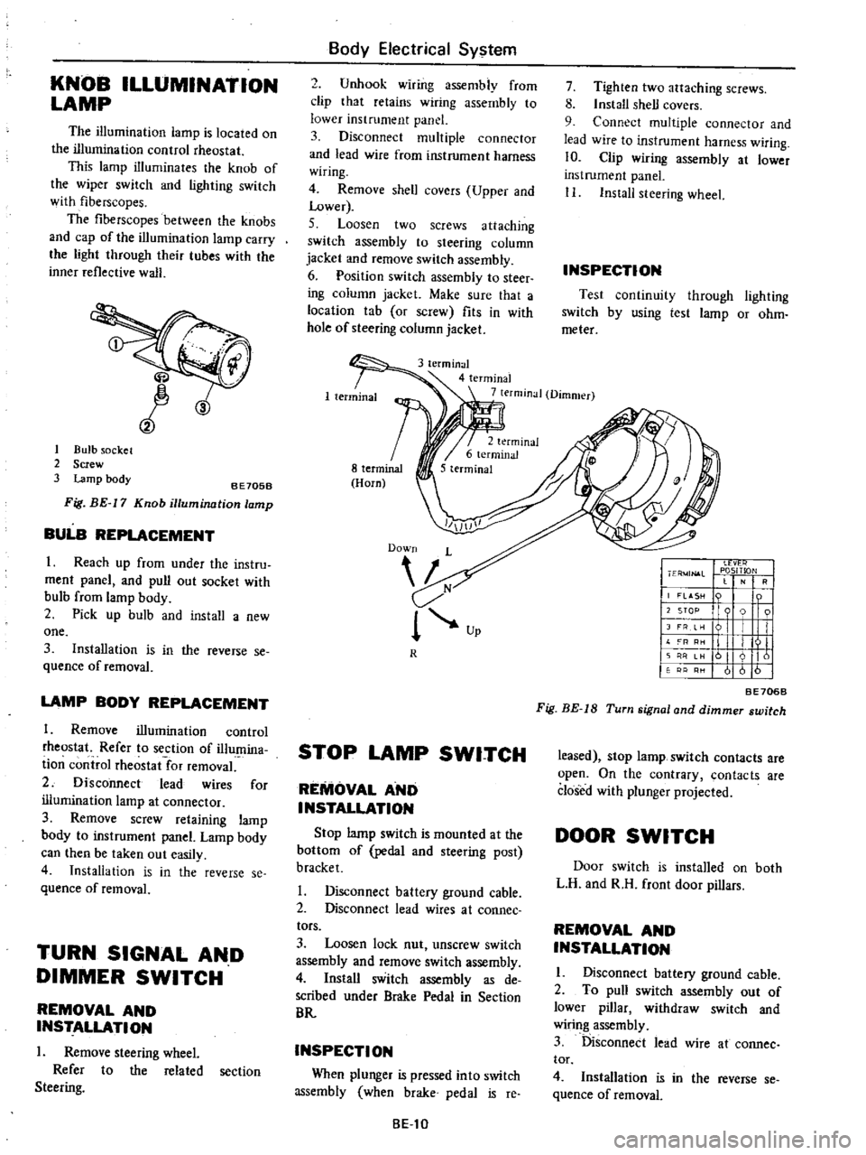
KNOB
ILLUMINATION
LAMP
The
illumination
lamp
is
located
on
the
illumination
control
rheostat
This
lamp
illuminates
the
knob
of
the
wiper
switch
and
lighting
switch
with
fiberscopes
The
fiberscopes
between
the
knobs
and
cap
of
the
illumination
lamp
carry
the
light
through
their
tubes
with
the
inner
reflective
walJ
CID
1
Bulb
socket
2
Screw
3
Lamp
body
8E705B
Fig
BE
17
Knob
illumination
lamp
BULB
REPLACEMENT
I
Reach
up
from
under
the
instru
ment
panel
and
pull
out
socket
with
bulb
from
lamp
body
2
Pick
up
bulb
and
install
a
new
one
3
Installation
is
in
the
reverse
se
quence
of
removal
LAMP
BODY
REPLACEMENT
1
Remove
illumination
control
rheostat
Refer
to
section
of
illumina
ti
on
control
rheostat
for
removal
2
Disconnect
lead
wires
for
illumination
lamp
at
connector
3
Remove
screw
retaining
lamp
body
to
instrument
panel
Lamp
body
can
then
be
taken
out
easily
4
Installation
is
in
the
reverse
se
quence
of
removal
TURN
SIGNAL
AND
DIMMER
SWITCH
REMOVAL
AND
INSTALLATION
I
Remove
steering
wheel
Refer
to
the
related
section
Steering
Body
Electrical
System
2
Unhook
wiring
assembly
from
clip
that
retains
wiring
assembly
to
lower
instrument
panel
3
Disconnect
multiple
connector
and
lead
wire
from
instrument
harness
wiring
4
Remove
shell
covers
Upper
and
Lower
5
Loosen
two
screws
attaching
switch
assembly
to
steering
column
jacket
and
remove
switch
assembly
6
Position
switch
assembly
to
steer
ing
column
jacket
Make
sure
that
a
location
tab
or
screw
fits
in
with
hole
of
steering
column
jacket
7
Tighten
two
attaching
screws
8
Install
shell
covers
9
Connect
multiple
connector
and
lead
wire
to
instrument
harness
wiring
10
Clip
wiring
assembly
at
lower
instrument
panel
II
Install
steering
wheel
INSPECTION
Test
continuity
through
lighting
switch
by
using
test
lamp
or
ohm
meter
3
terminal
4
terminal
7
terminal
Dimmer
R
STOP
LAMP
SWITCH
REMOVAL
AND
INSTALLATION
Stop
lamp
switch
is
mounted
at
the
bottom
of
pedal
and
steering
post
bracket
I
Disconnect
battery
ground
cable
2
Disconnect
lead
wires
at
coonee
tors
3
Loosen
lock
nut
unscrew
switch
assembly
and
remove
switch
assembly
4
Install
switch
assembly
as
de
scribed
under
Brake
Pedal
in
Section
BR
INSPECTION
When
plunger
is
pressed
into
switch
assembly
when
brake
pedal
is
reo
8El0
I
Ll
vt
r
I
ER
4JN
l
L
PlOSITlON
RI
j
LASH
n
I
I
12
STOP
9
91
I
JFRe
I
I
II
L
I
III
11
I
I
II
161
I
61616
BE706B
Fig
BE
IS
Turn
signal
and
dimmer
switch
leased
stop
lamp
switch
contacts
are
open
On
the
contrary
contacts
are
closed
with
plunger
projected
DOOR
SWITCH
Door
switch
is
installed
on
both
L
H
and
R
H
front
door
pillars
REMOVAL
AND
INSTALLATION
I
Disconnect
battery
ground
cable
2
To
pull
switch
assembly
out
of
lower
pillar
withdraw
switch
and
wiring
assembly
3
Disconnect
lead
wire
at
cannee
tor
4
Installation
is
in
the
reverse
se
quence
of
removal
Page 456 of 537
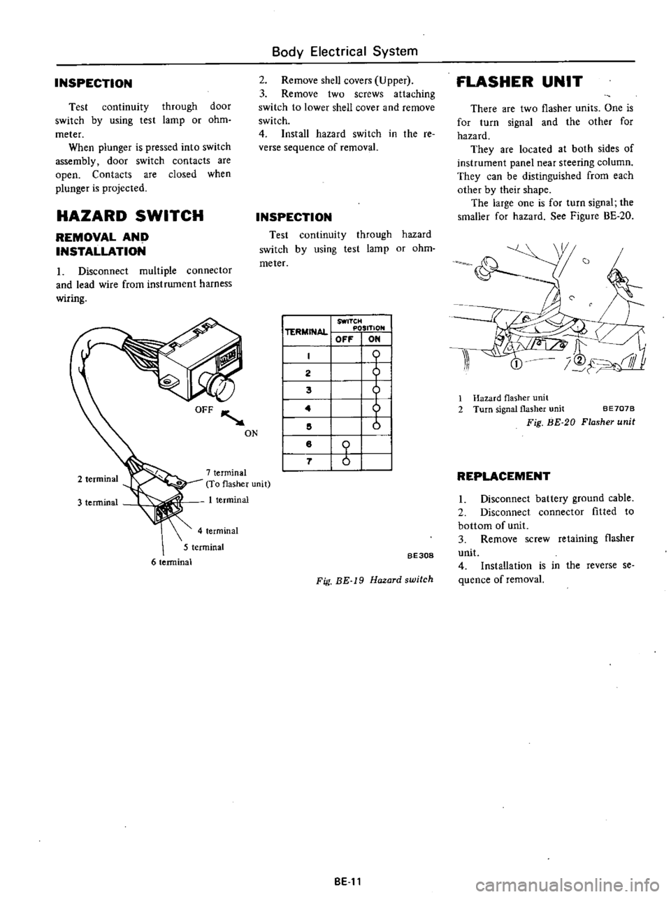
INSPECTION
through
door
lamp
or
ohm
Test
continuity
switch
by
using
test
meter
When
plunger
is
pressed
into
switch
assembly
door
switch
contacts
are
open
Contacts
are
closed
when
plunger
is
projected
HAZARD
SWITCH
REMOVAL
AND
INSTALLATION
1
Disconnect
multiple
connector
and
lead
wire
from
instrwnent
harness
wiring
3
terminal
7
terminal
To
flasher
unit
1
terminal
4
terminal
5
terminal
6
terminal
I
TERMINAL
SWITCH
POSITION
OFF
ON
I
lli
ill
I
2
I
5
1
Hazard
flasher
unit
I
4
2
Turn
signal
flasher
unit
BE707B
I
5
Fig
BE
20
Flasher
unit
I
8
I
7
I
REPLACEMENT
Body
Electrical
System
2
Remove
shell
covers
Upper
3
Remove
two
screws
attaching
switch
to
lower
shell
cover
and
remove
switch
4
Install
hazard
switch
in
the
re
verse
sequence
of
removal
INSPECTION
Test
continuity
through
hazard
switch
by
using
test
lamp
or
ohm
meter
ON
BE308
Fig
BE
19
Hazard
switch
BE
11
FLASHER
UNIT
There
are
two
flasher
units
One
is
for
turn
signal
and
the
other
for
hazard
They
are
located
at
both
sides
of
instrument
panel
near
steering
column
They
can
be
distinguished
from
each
other
by
their
shape
The
large
one
is
for
turn
signal
the
smaller
for
hazard
See
Figure
BE
20
I
Disconnect
battery
ground
cable
2
Disconnect
connector
fitted
to
bottom
of
unit
3
Remove
screw
retaining
flasher
unit
4
Installation
is
in
the
reverse
se
quence
of
removal
Page 534 of 537
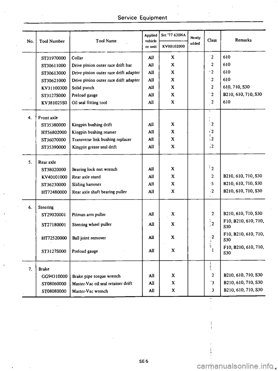
Service
Equipment
Applied
Ser
77
620NA
Newly
No
Tool
Number
Tool
Name
vehicle
Class
Remarks
added
or
unit
KVOO
102000
ST31970000
Collar
All
X
2
610
ST30611000
Drive
pinion
outer
race
drift
bar
All
X
2
610
ST30613000
Drive
pinion
outer
race
drift
adapter
All
X
2
610
ST3062
1000
Drive
pinion
outer
race
drift
adapter
All
X
2
610
KV311
00300
Solid
punch
All
X
2
610
710
S30
ST3127S000
Preload
gauge
All
X
2
B21O
610
710
S30
KV381025S0
Oil
seal
fitting
tool
All
X
2
610
4
Front
axle
ST35380000
Kingpin
bushing
drift
All
X
2
HT56802000
Kingpin
bushing
reamer
All
X
2
ST36070000
Transverse
link
bushing
replacer
All
X
2
ST35390000
Kingpin
grease
seal
drift
All
X
2
5
Rear
axle
ST38020000
Bearing
lock
nut
wrench
All
X
2
KV40101000
Rear
axle
stand
All
X
2
B210
610
710
S30
ST36230000
Sliding
hammer
All
X
5
B210
610
710
S30
HT72480000
Rear
axle
shaft
bearing
puller
All
X
2
B210
610
710
S30
6
Steering
ST2902000
I
Pitman
arm
puller
All
X
2
B210
610
710
S30
ST27
180001
Steering
wheel
puller
All
X
2
FIO
B210
610
710
S30
HT72520000
Ball
joint
remover
All
X
2
FIO
B210
610
710
S30
ST3127S000
Preload
gauge
All
X
FlO
B210
610
710
S30
7
Brake
GG943
10000
Brake
pipe
torque
wrench
All
X
2
B210
610
710
S30
ST08060000
Master
Vac
oil
seal
retainer
drift
All
X
3
B210
610
710
S30
ST08080000
Master
Vac
wrench
All
X
3
B210
610
710
S30
SE
5