steering DATSUN PICK-UP 1977 Service Manual
[x] Cancel search | Manufacturer: DATSUN, Model Year: 1977, Model line: PICK-UP, Model: DATSUN PICK-UP 1977Pages: 537, PDF Size: 35.48 MB
Page 10 of 537
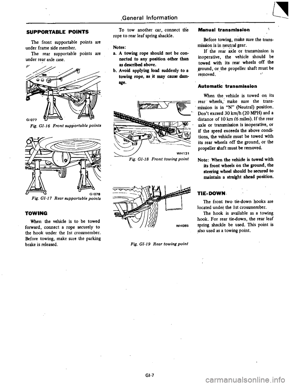
SUPPORTABLE
POINTS
The
front
supportable
points
are
under
frame
side
member
The
rear
supportable
points
are
under
rear
axle
case
Fig
GI
16
Front
supportable
points
v
GI078
Fig
GI
17
Rear
supportable
points
TOWING
When
the
vehicle
is
to
be
towed
forward
connect
a
rope
securely
to
the
hook
under
the
1st
CrosSIn
ember
Before
towing
make
sure
the
parking
brake
is
released
General
Information
To
tow
another
car
connect
t1ie
rope
to
rear
leaf
spring
shackle
Notes
a
A
towing
rope
should
not
be
con
nected
to
any
position
other
than
as
described
above
b
Avoid
applying
load
suddenly
to
a
towing
rope
as
it
may
cause
dam
age
WH131
Fig
Gl
18
Fronttowing
point
Fig
01
19
Rear
towing
point
GI
7
Manual
transmission
Before
towing
make
sure
the
trans
mission
is
in
neutral
gear
If
the
rear
axle
or
transmission
is
inoperative
the
vehicle
should
be
towed
with
its
rear
wheels
off
the
ground
or
the
propeller
shaft
must
be
re
l1oved
Automatic
transmission
When
the
vehicle
is
towed
on
its
rear
wheels
make
sure
the
trans
mission
is
in
N
Neutral
position
Don
t
exceed
30
km
h
20
MPH
and
a
distance
of
Hi
kin
6
miles
If
the
rear
axle
or
transmission
is
inoperative
or
if
the
speed
exceed
the
above
condi
tions
the
vehicle
must
be
towed
with
its
rear
wheels
off
the
ground
or
the
propeller
shaft
must
be
removed
Note
When
the
vehicle
is
towed
with
its
front
wheels
on
the
ground
the
steering
wheel
shouId
be
secured
to
maintain
a
straight
ahead
position
TIE
DOWN
The
front
two
tie
down
hooks
are
located
under
the
1st
crosSInember
The
hook
is
available
as
a
towing
hook
For
rear
tie
down
the
rear
leaf
spring
shackle
be
used
lIDs
point
is
also
used
as
a
towing
point
Page 11 of 537
General
Information
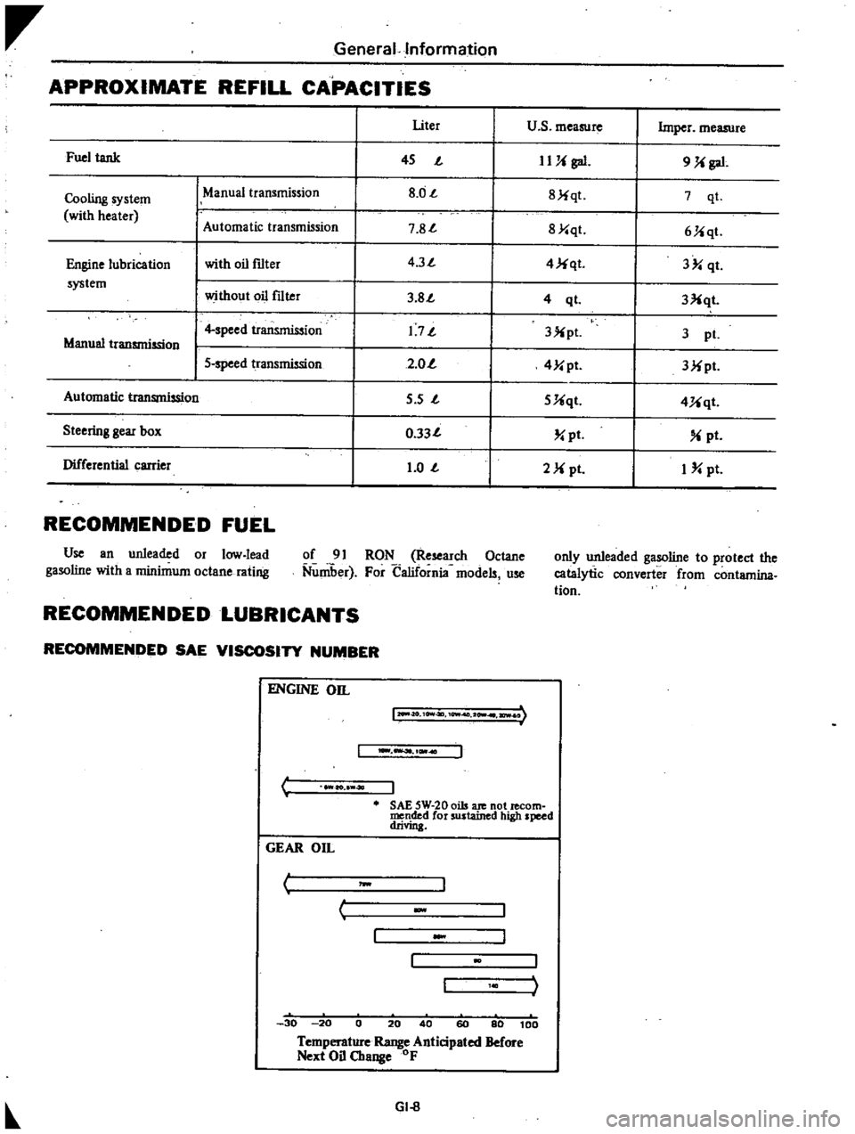
APPROXIMATE
REFILL
CAPACITIES
I
Uter
u
s
measure
Imper
measure
Fuel
tank
I
45
J
IUi
gal
9
Ji
gal
Cooling
system
ManUal
transmission
I
8
0J
I
8Jiqt
7
qt
with
heater
Automatic
tr
smission
I
7
8J
I
8Y
qt
6Jiqt
Engine
lubrication
with
oil
f1lter
I
4
3J
I
4
Ji
qt
3
qt
system
without
oil
f1lter
I
3
8J
I
3Xqt
4
ql
I
4
speed
transmission
I
1
7J
I
3X
pl
3
pI
Manual
transmission
I
5
speed
transmission
I
2
0
I
4Y
pt
3Mpt
Automatic
transmission
I
5
s
J
I
5Uqt
4Uqt
Steering
gear
box
I
0
33J
I
pt
pt
Differential
carrier
I
1
0
J
I
2M
pI
I
pt
RECOMMENDED
FUEL
Use
an
unleaded
or
low
lead
gasoline
with
a
minimum
octane
rating
of
91
RON
Research
Octane
Nuniber
For
California
models
use
only
unleaded
gasoline
to
protect
the
catalytic
converter
from
contamina
tion
RECOMMENDED
LUBRICANTS
RECOMMENDED
SAE
VISCOSITY
NUMBER
C
ENGINE
on
12O
II
O
10Vt4ll
10Wf
2
I
ICWI
I
ao
40
J
SAE
5W
20
oils
ate
not
lecom
mended
for
sustained
high
speed
drivin
GEAR
On
I
J
w
c
30
20
0
20
40
60
80
100
Temperature
Range
Anticipated
Before
Next
Oil
Change
OF
GI
8
Page 12 of 537
General
Information
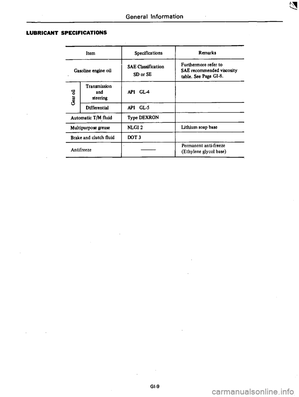
LUBRICANT
SPECIFICATIONS
Item
Specifications
Remarks
SAE
Classification
Furthermore
refer
to
Gasoline
engine
oil
SD
or
SE
SAE
recommended
viscosity
table
See
Poge
GI
B
Transmission
and
API
GL
4
0
steering
Differential
API
GL
S
Automatic
TIM
fluid
Type
DEXRON
Multipurpose
grea
NLGI2
lithium
soap
base
Brake
and
clutch
fluid
DOT
3
Permanent
anti
freeze
Antifreeze
Ethylene
glycol
ba
e
GI
9
Page 220 of 537
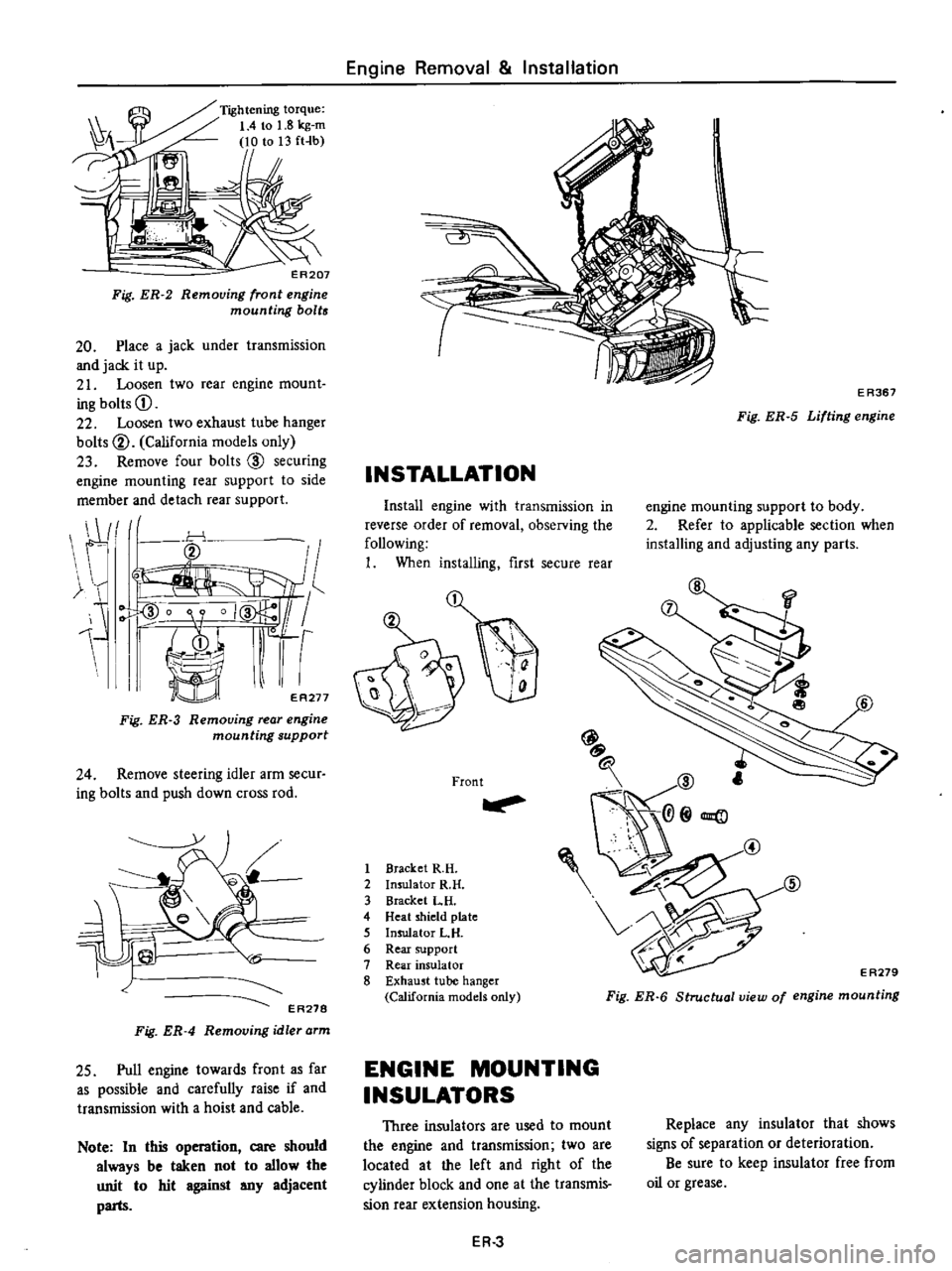
Fig
ER
2
ER207
Removing
front
engine
mounting
bolts
20
Place
a
jack
under
transmission
and
jack
it
up
21
Loosen
two
rear
engine
mount
ing
bolts
CD
22
Loosen
two
exhaust
tube
hanger
bolts
V
California
models
only
23
Remove
four
bolts
CID
securing
engine
mounting
rear
support
to
side
member
and
detach
rear
support
j
r
O
1
ER271
Fig
ER
3
Removing
rear
engine
mounting
support
24
Remove
steering
idler
arm
secur
ing
bolts
and
push
down
cross
rod
iC
EA278
Fig
ER
4
Removing
idler
arm
25
Pull
engine
towards
front
as
far
as
possible
and
carefully
raise
if
and
transmission
with
a
hoist
and
cable
Note
In
this
r
an
care
should
always
be
taken
not
to
allow
the
unit
to
hit
against
any
adjacent
parts
Engine
Removal
Installation
INSTALLATION
E
R367
Fig
ER
5
Lifting
engine
Install
engine
with
transmission
in
reverse
order
of
removal
observing
the
following
I
When
installing
first
secure
rear
2
Front
1
Bracket
R
H
2
Insulator
R
H
3
Bracket
LH
4
Heat
shield
plate
5
Insulator
L
H
6
Rear
support
7
Rear
insulator
8
Exhaust
tube
hanger
California
models
only
engine
mounting
support
to
body
2
Refer
to
applicable
section
when
installing
and
adjusting
any
parts
@
E
A279
Fig
ER
6
Structual
view
of
engine
mounting
ENGINE
MOUNTING
INSULATORS
Three
insulators
are
used
to
mount
the
engine
and
transmission
two
are
located
at
the
left
and
right
of
the
cylinder
block
and
one
at
the
transmis
sion
rear
extension
housing
Replace
any
insulator
that
shows
signs
of
separation
or
deterioration
Be
sure
to
keep
insulator
free
from
oil
or
grease
ER
3
Page 351 of 537
Front
Axle
Front
Suspension
FRONT
AXLE
AND
FRONT
SUSPENSION
CONTENTS
GENERAL
DESCRIPTION
FRONT
AXLE
REMOVAL
AND
INSTALLATION
WHEEL
BEARING
ADJUSTMENT
DISASSEMBLY
AND
ASSEMBLY
INSPECTION
SHOCK
ABSORBER
REMOVAL
AND
INSTALLATION
INSPECTION
STABILIZER
REMOVAL
AND
INSTALLATION
INSPECTION
TENSION
ROD
FA
2
FA
3
FA
3
FA
4
FA
4
FA
5
FA
8
FA
8
FA
8
FA
8
FA
8
FA
8
FA
8
REMOVAL
AND
INSTALLATION
INSPECTION
TORSION
BAR
SPRING
REMOVAL
AND
INSTALLATION
INSPECTION
UPPER
AND
LOWER
LINKS
FjEMOVAL
AND
INSTALLATION
DISASSEMBLY
AND
ASSEMBLY
INSPECTION
ADJUSTMENT
VEHICLE
POSTURE
WHEEL
ALIGNMENT
STEERING
ANGLE
GENERAL
DESCRIPTION
uUl
FA
8
FA
9
FA
9
FA
9
FA
9
FA
10
FA
l0
FA
ll
FA
ll
FA
Il
FA
ll
FA
12
FA
12
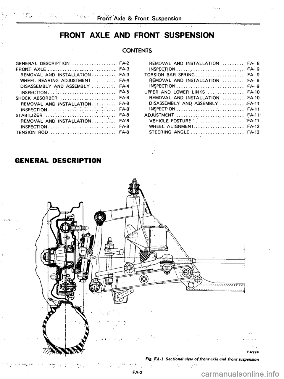
FA224
Fig
FA
j
SectionallJiew
of
fronta
xle
and
fron
t
suspension
FA
2
Page 352 of 537
The
design
of
the
front
suspension
adopts
the
independent
double
wishbone
type
suspension
used
the
torsion
bar
spring
Both
the
upper
and
lower
links
are
installed
on
the
bracket
which
is
welded
on
the
frame
A
1d
the
above
links
swing
to
allow
the
knuckle
spindle
to
move
freely
in
a
vertical
dimension
The
top
and
bottom
of
the
knuckle
spindle
support
are
connected
to
the
upper
link
through
rubber
bushing
and
to
the
lower
lick
through
screw
bushing
The
tension
rod
held
by
the
brack
ets
on
the
chassis
frame
and
lower
lick
wiih
rubber
bushings
bears
the
force
of
fore
and
aft
direction
The
front
end
of
the
torsion
bar
spring
is
installed
to
the
torque
arm
which
attaches
to
the
lower
link
The
opposite
end
is
installed
to
the
spring
anchor
that
secures
to
chassis
frame
firmly
The
both
ends
of
the
torsion
bar
spring
are
serrated
The
shock
absorber
is
double
action
telescopic
hydraulic
type
The
upper
stem
is
attached
to
the
bracket
of
the
chassis
frame
The
lower
insulated
bracket
is
bolted
to
the
lower
lick
The
bumper
rubber
secured
to
the
bracket
Of
the
frame
limits
the
verti
cal
motion
of
the
suspension
lick
The
knuckle
spindle
is
connecied
to
the
k
ufkle
spindle
arm
by
the
king
pin
The
king
pin
bushings
are
fitted
to
the
upper
and
lower
arm
portIOns
of
the
knuckle
spindle
and
seals
are
provided
at
the
portions
mentioned
to
keep
water
and
dirt
from
enteri
g
The
knuckle
arm
is
connected
to
the
lower
end
of
the
knuckle
spindle
to
transmit
ttLe
movement
of
the
steering
wheel
to
the
knuckle
spindle
The
wheel
hub
is
supported
by
two
taper
roller
bearings
on
the
knuckle
spindle
Tlie
brake
drum
and
wheel
are
secured
to
ihe
hub
by
the
hub
bolts
Front
Axle
Front
Suspension
FRONT
AXLE
REMOVAL
AND
INSTALLATION
Removal
I
Jack
up
and
support
vehicle
on
the
stands
at
the
frame
in
a
safe
manner
2
Remove
front
wheel
3
Re
ove
brake
hose
together
with
connector
from
wheel
cylinder
4
Remove
brake
drum
S
Remove
hub
cap
and
then
remove
cotter
pin
adjusting
cap
and
spindle
nut
from
knuckle
spindle
6
Remove
wheel
hub
outer
and
inner
wheel
bearings
bearing
washer
and
grease
seal
from
knuckle
spindle
7
Remove
brake
disc
assembly
from
the
flange
of
knuckle
spindle
8
Remove
knuckle
arm
from
knuckle
spindle
9
Remove
king
pin
lock
bolt
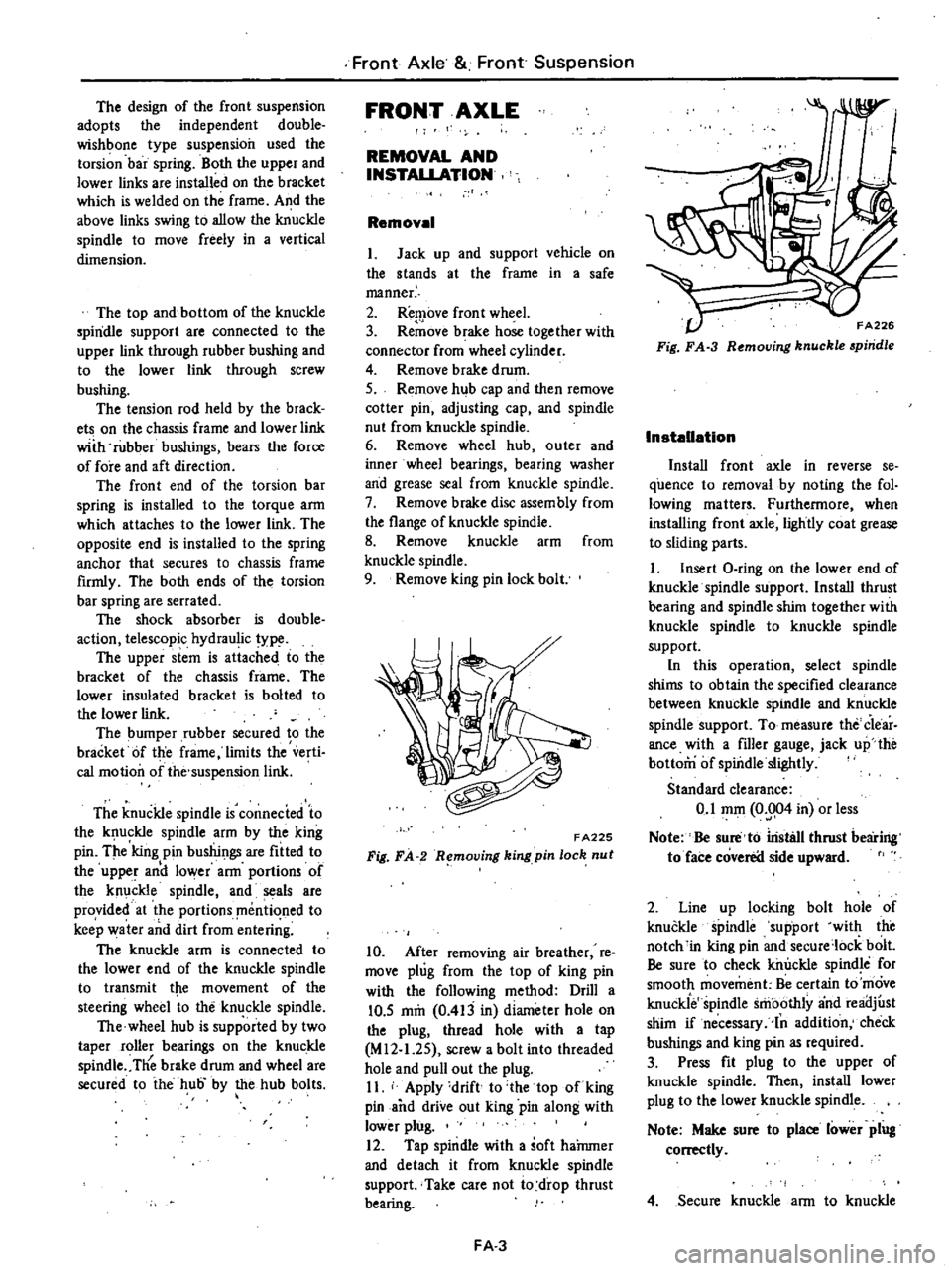
FA225
Fig
FA
R
mol1ing
king
pin
loch
nut
10
After
removing
air
breather
re
move
plug
from
the
top
of
king
pin
with
the
following
method
Drill
a
10
5
mm
0
413
in
diameter
hole
on
the
plug
thread
hole
with
a
tap
M
12
1
2S
screw
a
bolt
into
threaded
hole
and
pull
out
the
plug
II
Apply
drift
to
the
top
of
king
pin
and
drive
out
king
pin
along
with
lower
plug
12
Tap
spindle
with
a
soft
haJnmer
and
detach
it
from
knuckle
spindle
support
Take
care
not
io
drop
thrust
bearing
FA
3
FA226
Fig
FA
3
R
moving
knuckle
piridle
Installation
Install
front
axle
in
reverse
se
quence
to
removal
by
noting
the
fol
lowing
matters
Furthermore
when
installing
front
axle
lightly
coat
grease
to
sliding
parts
I
Insert
O
ring
on
the
lower
end
of
knuckle
spindle
support
Install
thrust
bearing
and
spindle
shim
together
with
knuckle
spindle
to
knuckle
spindle
support
In
this
operation
select
spindle
shims
to
obtain
the
specified
clearance
between
knuckle
spindle
and
knuckle
spindle
support
To
measure
the
Clear
ance
with
a
filler
gauge
jack
up
the
bottom
of
spindle
slightly
Standard
clearance
0
1
mOl
0
004
in
or
less
Note
Be
sure
to
iristsll
thrust
bearing
to
face
coverea
side
upward
2
Line
up
locking
bolt
hole
of
knuckle
spindle
support
with
the
notch
in
king
pin
and
secure
lock
bolt
Be
sure
to
check
killJckle
spindle
for
smooth
movement
Be
certain
to
move
knuckie
spindle
smoothly
and
reailjust
shim
if
necessary
In
addition
check
bushings
and
king
pin
as
required
3
Press
fit
plug
to
the
upper
of
knuckle
spindle
Then
install
lower
plug
to
the
lower
knuckle
spindle
Note
Make
sure
to
place
lower
plug
conectly
4
Secure
knuckle
arm
to
knuckle
Page 361 of 537
WHEEL
ALIGNMENT
Correct
front
wheel
alignment
attains
proper
vehicle
handling
charac
teristics
and
the
least
steering
effort
with
a
minimum
amount
of
tire
wear
Before
adjusting
front
wheel
align
ment
make
sure
to
carry
out
a
pre
liminary
inspection
of
the
front
end
parts
for
the
following
conditions
1
Tire
pressure
and
balance
2
Wheel
bearings
and
nuts
3
Steering
gear
play
4
Steering
gear
housing
at
frame
S
Steering
linkage
and
connections
6
Shock
absorber
action
When
using
the
equipment
for
front
wheel
alignment
inspection
follow
the
inst
c
tions
furnished
with
the
equip
ment
Furthennore
the
inspection
should
be
made
with
the
vehicle
level
and
at
curb
weight
Camber
and
caster
Measure
camber
and
caster
and
adjust
them
in
accordance
with
the
following
procedures
if
necessary
Both
camber
and
caster
are
ad
justed
by
increasing
and
decreasing
thickness
of
adjust
shim
inserted
be
tween
upper
link
spindle
and
upper
link
mounting
bracket
To
adjust
caster
make
a
difference
between
thickness
of
front
and
rear
shims
By
adding
a
shim
I
mm
0
039
in
at
front
side
caster
will
be
de
creased
by
33
At
the
same
time
camber
will
also
be
decreased
by
6
S
To
adjust
camber
add
or
remove
an
equal
amount
of
shims
to
front
and
rear
sides
By
adding
a
pack
of
shims
I
mOl
0
039
in
thick
at
both
sides
camber
will
be
decreased
by
13
Shims
are
available
in
I
mm
0
039
in
2
mOl
0
079
in
and
4
mOl
0
157
in
thickness
Front
Axle
Front
Suspension
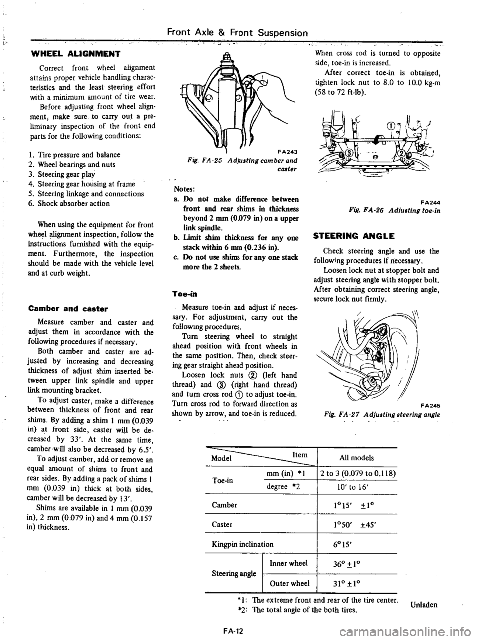
FA243
Fig
FA
25
Adjustingcamberand
cCJ
ter
Notes
a
Do
not
make
difference
between
front
and
rear
shims
in
thickness
beyond
2
mm
0
079
in
on
a
upper
link
spindle
b
Umit
shim
thickness
for
anyone
stack
within
6
nun
0
236
in
c
Do
not
use
shims
for
anyone
stack
more
the
2
sheets
Toe
in
Measure
toe
in
and
adjust
if
neces
sary
For
adjustment
carry
out
the
follOWIng
procedures
Turn
steering
wheel
to
straight
ahead
position
with
front
wheels
in
the
same
position
Then
check
steer
ing
gear
straight
ahead
position
Loosen
lock
nuts
@
left
hand
thread
and
ID
right
hand
thread
and
turn
cross
rod
CD
to
adjust
toe
in
Turn
cross
rod
to
forward
direction
as
shown
by
arrow
and
toe
in
is
reduced
When
cross
rod
is
turned
to
opposite
side
toe
in
is
increased
After
correct
toe
in
is
obtained
tighten
lock
nut
to
8
0
to
10
0
kg
m
S8
to
72
ft
Ib
r
J
r
CD
0
HI
r
I
e
f
FA244
Fig
FA
26
Adju6ting
toe
in
STEERING
ANGLE
Check
steering
angle
and
use
the
follow
ng
procedures
if
necessary
Loosen
lock
nut
at
stopper
bolt
and
adjust
steering
angle
with
stopper
bolt
Mter
obtaining
correct
steering
angle
secure
lock
nut
firmly
FA245
Fig
FA
27
Adjusting
steering
angle
Model
Item
All
models
mOl
in
1
2
to
3
0
079
to
0
118
Toe
in
degree
2
10
to
16
Camber
lOIS
Io
Caster
10SO
4S
I
60IS
Kingpin
inc
inal10n
I
Inner
wheel
360
10
Steering
angle
I
Outer
wheel
310
10
1
The
extreme
front
and
rear
of
the
tire
center
Unladen
2
The
total
angle
of
the
both
tires
FA
12
Page 363 of 537
Front
Axle
Front
Suspension
TROUBLE
DIAGNOSES
AND
CORRECTIONS
Condition
Vibration
shock
and
shimmy
ing
of
steering
wheeL
Vehicle
pulls
to
right
or
left
Probable
cause
Vibration
Too
much
backlash
of
steering
gear
wear
of
each
part
of
linkage
and
vibration
of
front
wheels
are
in
many
cases
transmitted
to
the
steering
wheel
This
is
Very
much
noticeable
when
traveJling
over
bad
roads
and
at
higher
speeds
Shock
When
the
front
wheels
are
travelling
over
bumpy
roads
the
play
of
the
steering
linkage
is
transmitted
to
the
steering
wheel
This
is
especially
noticeable
when
travelling
rough
road
Shimmy
Abnormal
vibrations
of
the
front
suspen
sion
group
and
the
whole
steering
linkage
which
occur
when
a
specific
speed
is
attained
Improper
air
pressure
of
tire
Unbalance
and
deformation
of
roadwheel
Unevenly
worn
tire
or
insufficient
tightening
Improperly
adjusted
or
worn
front
wheel
bearing
Faulty
wheel
alignment
Worn
or
loose
suspension
link
screw
bushing
Damaged
idler
arm
Insufficiently
tightened
steering
gear
housing
Worn
steering
linkage
Improper
steering
gear
adjustment
insufficient
back
lash
Faulty
shock
absorber
or
loose
installation
Unbalanced
vehicle
posture
When
driving
with
hands
off
the
steering
wheel
on
a
fiat
road
the
vehicle
gently
swerves
to
right
or
left
Note
A
faulty
rear
suspension
may
also
be
the
cause
of
this
condition
and
therefore
see
also
the
chapter
dealing
with
the
rear
suspension
Improper
air
pressure
of
tire
or
insufficient
tightening
of
wheel
nu
ts
Difference
in
height
of
right
and
left
tire
treads
Incorrect
adjustment
or
abrasion
of
front
wheel
bearing
Weakened
front
torsion
spring
or
deviation
from
standard
specification
Improper
wheel
alignment
Worn
or
loose
suspension
link
screw
bushing
FA
14
Corrective
action
Adjust
Correct
the
unbalance
or
re
place
Replace
or
tighten
Adjust
or
replace
Adjust
Replace
Replace
TIghten
Replace
ball
joint
Adjust
Replace
or
tighten
Adjust
Adjust
or
tighten
Replace
tires
Adjust
or
replace
Replace
Readjust
Replace
Page 364 of 537
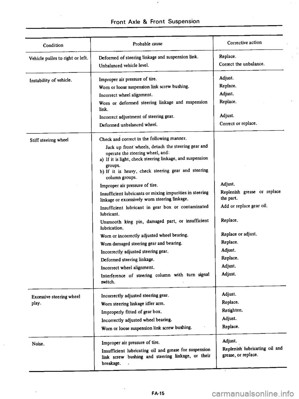
Condition
Vehicle
puBes
to
right
or
left
Instability
of
vehicle
Stiff
steeirng
wheel
Excessive
steering
wheel
play
Noise
Front
Axle
Front
Suspension
Probable
cause
Deformed
of
steering
linkage
and
suspension
link
Unbalanced
vehicle
level
Improper
air
pressure
of
tire
Worn
or
loose
suspension
link
screw
bushing
Incorrect
wheel
alignment
Worn
or
deformed
steering
linkage
and
suspension
link
Incorrect
adjustment
of
steering
gear
Deformed
unbalanced
wheel
Check
and
correct
in
the
following
manner
Jack
up
front
wheels
detach
the
steering
gear
and
operate
the
steering
wheel
and
a
If
it
is
light
check
steering
linkage
and
suspension
groups
b
If
it
is
heavy
check
steering
gear
and
steering
column
groups
Improper
air
pressure
of
tire
Insufficient
lubricants
or
mixing
impurities
in
steering
linkage
or
excessively
worn
steering
linkage
Insufficient
lubricant
in
gear
box
or
contaminated
lubricant
Unsmooth
king
pin
damaged
part
Or
insufficient
lubrication
Worn
or
incorrectly
adjusted
wheel
bearing
Worn
damaged
steering
gear
and
bearing
Incorrectly
adjusted
steering
gear
Deformed
steering
linkage
Incorrect
wheel
alignment
Interference
of
steering
column
with
turn
signal
switch
Incorrectly
adjusted
steering
gear
Worn
steering
linkage
idler
arm
Improperly
fitted
of
gear
box
Incorrectly
adjusted
wheel
bearing
Worn
or
loose
suspension
link
screw
bushing
Improper
air
pressure
of
tire
Insufficient
lubricating
oil
and
grease
for
suspension
link
screw
bushing
and
steering
linkage
or
their
breakage
FA
15
Corrective
action
Replace
Correct
the
unbalance
Adjust
Replace
Adjust
Replace
Adjust
Correct
or
replace
Adjust
Replenish
grease
or
replace
the
part
Add
or
replace
gear
oil
Replace
Replace
or
adjust
Replace
Adjust
Replace
Adjust
Adjust
Adjust
Replace
Retighten
Adjust
Replace
Adjust
Replenish
lubricating
oil
and
grease
or
replace
Page 365 of 537
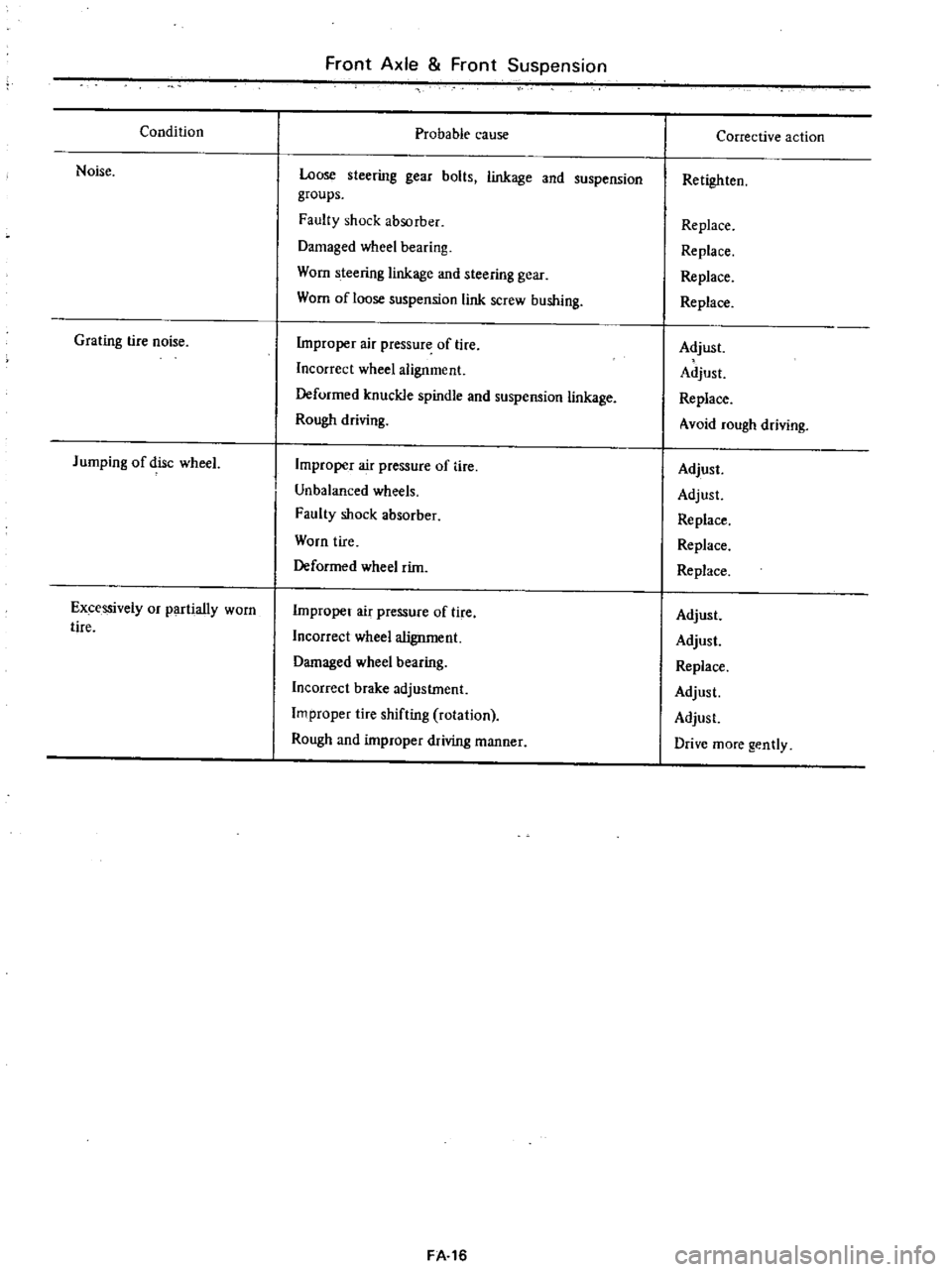
Condition
Noise
Grating
tire
noise
Jumping
of
disc
wheeL
Excessively
or
partially
worn
tire
Front
Axle
Front
Suspension
Probable
cause
Loose
steering
gear
bolts
linkage
and
suspension
groups
Faulty
shock
absorber
Damaged
wheel
bearing
Worn
steering
linkage
and
steering
gear
Worn
of
loose
suspension
link
screw
bushing
Improper
air
pressure
of
lire
Incorrect
wheel
alignment
Deformed
knuckle
spindle
and
suspension
linkage
Rough
driving
Improper
air
pressure
of
tire
Unbalanced
wheels
Faulty
shock
absorber
Worn
tire
Deformed
wheel
rim
Improper
air
pressure
of
tire
Incorrect
wheel
alignment
Damaged
wheel
bearing
Incorrect
brake
adjustment
Improper
tire
shifting
rotation
Rough
and
improper
wiving
manner
FA
16
Corrective
action
Retighten
Replace
Replace
Replace
Replace
Adjust
Adjust
Replace
Avoid
rough
driving
Adjust
Adjust
Replace
Replace
Replace
Adjust
Adjust
Replace
Adjust
Adjust
Drive
more
gently