seat adjustment DATSUN PICK-UP 1977 Service Manual
[x] Cancel search | Manufacturer: DATSUN, Model Year: 1977, Model line: PICK-UP, Model: DATSUN PICK-UP 1977Pages: 537, PDF Size: 35.48 MB
Page 23 of 537
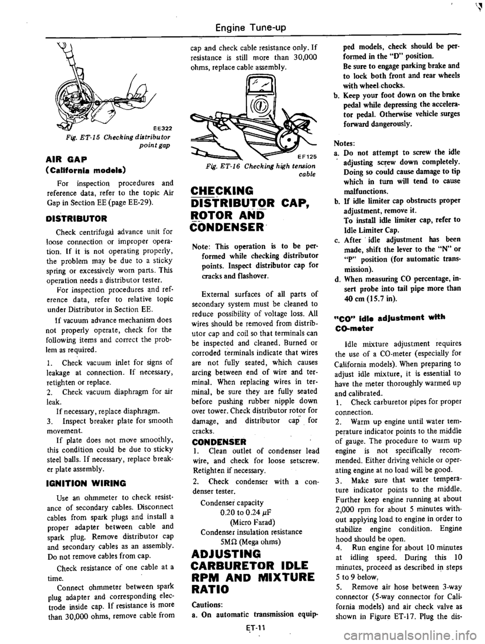
EE322
Fig
ET
15
Checking
diltribu
tor
point
gap
AIR
GAP
California
models
For
inspection
procedures
and
reference
data
refer
to
the
topic
Air
Gap
in
Section
EE
page
EE
29
DISTRIBUTOR
Check
centrifugal
advance
unit
for
loose
connection
or
improper
opera
tion
If
it
is
not
operating
properly
the
problem
may
be
due
to
a
sticky
spring
or
excessively
worn
parts
This
operation
needs
a
distributor
tester
For
inspection
procedures
and
ref
erence
data
refer
to
relative
topic
under
Distributor
in
Section
EE
If
vacuum
advance
mechanism
does
not
properly
operate
check
for
the
following
items
and
correct
the
prob
lem
as
required
1
Check
vacuum
inlet
for
signs
of
leakage
at
connection
If
necessary
retighten
or
replace
2
Check
vacuum
diaphragm
for
air
leak
If
necessary
replace
diaphragm
3
Inspect
breaker
plate
for
smooth
movement
If
plate
does
not
move
smoothly
this
condition
could
be
due
to
sticky
steel
balls
If
necessary
replace
break
er
plate
assembly
IGNITION
WIRING
Use
an
ohmmeter
to
check
resist
ance
of
secondary
cables
Disconnect
cables
from
spark
plugs
and
install
a
proper
adapter
between
cable
and
spark
plug
Remove
distributor
cap
and
secondary
cables
as
an
assembly
Do
not
remove
cables
from
cap
Check
resistance
of
one
cable
at
a
time
Connect
ohmmeter
between
spark
plug
adapter
and
corresponding
elec
trade
inside
cap
If
resistance
is
more
than
30
000
ohms
remove
cable
from
Engine
Tune
up
cap
and
check
cable
resistance
only
If
resistance
is
still
more
than
30
000
ohms
replace
cable
assembly
EF125
Checking
high
tension
cable
CHECKING
DISTRIBUTOR
CAP
ROTOR
AND
CONDENSER
Note
This
operation
is
to
be
per
formed
while
checking
distributor
points
Inspect
distributor
cap
for
cracks
and
flashover
External
surfaces
of
all
parts
of
secondary
system
must
be
cleaned
to
reduce
possibility
of
voltage
loss
All
wires
should
be
removed
from
distrib
utor
cap
and
coil
so
that
terminals
can
be
inspected
and
cleaned
Burned
or
corroded
terminals
indicate
that
wires
are
not
fully
seated
which
causes
arcing
between
end
of
wire
and
ter
minal
When
replacing
wires
in
ter
minai
be
sure
they
are
fully
seated
before
pushing
rubber
nipple
down
over
tower
Check
distributor
rotor
for
damage
and
distributor
cap
for
cracks
CONDENSER
I
Clean
outlet
of
condenser
lead
wire
and
check
for
loose
setscrew
Retighten
if
necessary
2
Check
condenser
with
a
con
denser
tester
Condenser
capacity
0
20
to
0
24
IF
Micro
Farad
Condenser
insulation
resistance
5Mn
Mega
ohms
ADJUSTING
CARBURETOR
IDLE
RPM
AND
MIXTURE
RATIO
Cautions
a
On
automatic
transmission
equip
T
11
ped
models
check
should
be
per
fonned
in
the
D
position
Be
sure
to
engage
parking
brake
and
to
lock
both
front
and
rear
wheels
with
wheel
chocks
b
Keep
your
foot
down
on
the
brake
pedal
while
depressing
the
accelera
tor
pedal
Otherwise
vehicle
surges
forward
dangerously
Notes
a
Do
not
attempt
to
screw
the
idle
adjusting
sc
ew
down
completely
Doing
so
could
cause
damage
to
tip
which
in
turn
will
tend
to
cause
malfunctions
b
If
idle
limiter
cap
obstructs
proper
adjustment
remove
it
To
install
idle
limiter
cap
refer
to
Idle
Limiter
Cap
c
After
idle
adjustment
has
been
made
shift
the
lever
to
the
N
or
P
position
for
automatic
trans
mission
d
When
measuring
CO
percentage
in
sert
probe
into
tail
pipe
more
than
40
em
15
7
in
CO
idle
adjustment
with
CD
meter
Idle
mixture
adjustment
requires
the
use
of
a
CO
meter
especially
for
California
models
When
preparing
to
adjust
idle
mixture
it
is
essential
to
have
the
meter
thoroughly
warmed
up
and
calibrated
I
Check
carburetor
pipes
for
proper
connection
2
Warm
up
engine
until
water
tem
perature
indicator
points
to
the
middle
of
gauge
The
procedure
to
warm
up
engine
is
not
specifically
recom
mended
Either
driving
vehicle
or
oper
ating
engine
at
no
load
will
be
good
3
Make
sure
that
water
tempera
ture
indicator
points
to
the
middle
Further
keep
engine
running
at
about
2
000
rpm
for
about
5
minutes
with
out
applying
load
to
engine
in
order
to
stabilize
engine
condition
Engine
hood
should
be
open
4
Run
engine
for
about
10
minutes
at
idling
speed
During
this
10
minutes
proceeq
as
described
i
steps
5
to
9
below
5
Remove
air
hose
between
3
way
connector
5
way
connector
for
Cali
fornia
models
and
air
check
valve
as
shown
in
Figure
ET
17
Plug
the
dis
Page 36 of 537
Replace
bulb
if
bulb
is
burned
ou
t
If
bulb
is
not
burned
trace
wireis
back
to
ignition
switch
Repair
or
replace
if
necessary
2
Be
sure
that
floor
temperature
is
cool
below
800C
1760F
before
carrying
out
the
following
procedure
1
Remove
rear
seat
2
Ignition
switch
is
turned
to
the
Temperature
sensing
switch
Temperature
warning
lamp
Contact
close
Off
Contact
open
On
Note
Avoid
heating
floor
tempera
ture
sensing
switch
directly
If
lamp
does
not
glow
check
floor
temperature
sensing
switch
connector
for
continuity
with
a
circuit
tester
If
continuity
should
exist
after
heated
surrounding
areas
of
floor
tern
rv
wnTP
sen
cinq
S
Vitch
reolace
tem
perature
sensing
switch
If
continuity
does
not
exist
trace
the
wiring
back
to
relay
or
check
the
following
step
3
Repair
or
replace
wire
s
if
necessary
Note
The
floor
temperature
sensing
switch
may
be
heated
through
the
floor
by
a
proper
heater
3
Turn
ignition
switch
to
the
IG
position
anf
disconnect
floor
temper
ature
sensing
connector
The
lamp
should
remain
on
If
not
check
floor
4
0
3
UJ
GJO
Engine
Tune
up
IGU
position
3
Ensure
that
floor
tem
perature
warning
lamp
goes
out
4
Heat
surrounding
areas
of
floor
temperature
sensing
switch
with
a
proper
heater
to
ensure
that
floor
temperature
warning
lamp
glows
when
floor
is
heated
to
lh
specifications
as
shown
in
the
table
below
Floor
temperature
Below
1050C
22IOF
Above
1050C
2210F
temperature
relay
for
continuity
with
a
circuit
tester
Referring
to
the
following
floor
temperature
relay
if
relay
is
normal
trace
wire
s
back
to
ignition
switch
Repair
faulty
wiring
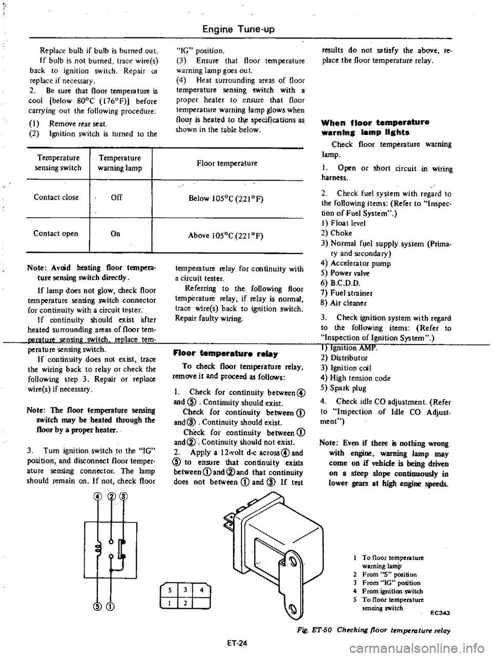
Floor
temperature
rela
To
check
floor
temperature
relay
remove
it
and
proceed
as
follows
1
Check
for
continuity
between@
and
@
Continuity
should
exist
Check
for
continuity
between
D
and@
Continuity
should
exist
Check
for
continuity
between
D
and@
Continuity
should
not
exist
2
Apply
a
12
volt
doC
across@and
@
to
ensure
that
continuity
exists
between
D
and@and
that
continuity
does
not
between
D
and
@
If
test
r
I
141
ET
24
results
do
not
satisfy
the
above
reo
place
the
floor
temperature
relay
When
floor
temperature
warnln8
lamp
118hts
Check
floor
temperature
warning
lamp
I
Open
or
short
circuit
in
wiring
harness
2
Check
fuel
system
with
regard
to
the
following
items
Refer
to
Inspec
tion
of
Fuel
System
I
Floa
t
level
2
Choke
3
Normal
fuel
supply
system
Prima
ry
and
secondary
4
Accelerator
pump
5
Power
valve
6
B
C
D
D
7
Fuel
strainer
8
Air
cleaner
3
Check
ignition
system
with
regard
to
the
following
items
Refer
to
Inspection
of
Ignition
System
I
IgnItion
AMI
2
Distributor
3
Ignition
coil
4
High
tension
code
5
Spark
plug
4
Check
idle
CO
adjustment
Refer
to
Inspection
of
Idle
CO
Adjust
roeoC
Note
Even
if
there
is
nothing
wrong
with
engine
warning
lamp
may
come
on
if
vehicle
is
being
driven
on
a
steep
slope
continuously
in
lower
gears
at
high
engine
speeds
To
floor
temperature
warning
lamp
2
From
S
position
3
From
GOt
position
4
From
ignition
switch
5
To
floor
temperature
sensing
switch
EC343
Fig
ET
50
Checking
floor
temperature
relay
Page 40 of 537

Engine
Tune
up
Condition
Probable
cause
Low
or
no
current
Ign
tion
system
out
of
order
Burned
distributor
point
Improper
point
gap
Faulty
condenser
Leak
at
rotor
cap
and
rotor
Faulty
spark
plug
Improper
ignition
timing
Faulty
ignition
coil
Disconnection
of
high
tension
cable
Loose
connection
or
disconnection
in
primary
circuit
Fuel
system
out
of
order
Lack
offuel
Dirty
fuel
strainer
Dirty
or
clogged
fuel
pipe
Fuel
pump
will
not
work
properly
Carburetor
choke
will
not
work
properly
Improper
adjustment
of
float
level
Improper
idling
Dirty
or
clogged
carburetor
Clogged
breather
pip
of
fuel
tank
Malfunctioning
an
ti
dieseling
solenoid
valve
Incorrect
sparle
plug
tightening
or
faulty
gasket
Improper
grade
engine
oil
or
low
viscosity
Incorrect
valve
clearance
Compression
leak
from
valve
seat
Sticky
valve
stem
Weak
or
damaged
valve
springs
Compression
leak
at
cylinder
head
gasket
Sticking
or
damaged
piston
ring
Worn
piston
ring
or
cylinder
Trouble
ooting
procedure
Pour
the
engine
oil
from
plug
hole
and
then
measure
cylinder
compression
Compression
increases
Compression
does
not
change
Low
comp
ion
ET
28
Corrective
action
Check
for
loose
terminal
or
disconnection
in
primary
circuit
Check
for
burned
points
Repair
or
replace
Adjust
Replace
Clean
or
replace
aean
adjust
plug
gap
or
replace
Adjust
Replace
Replace
Repair
or
replace
Supply
Replace
Clean
Repair
or
replace
Check
and
adjust
Correct
Adjust
Disassemble
and
clean
Repair
and
clean
Check
for
loose
terminal
or
wire
harness
Tighten
to
normal
torque
or
replace
gasket
Replace
with
proper
grade
oil
Adjust
Remove
cyljnder
head
and
lap
valves
Correct
or
replace
valve
and
valve
guide
Replace
valve
springs
Replace
gasket
Replace
piston
rings
Overhaul
engine
Malfunctiong
cylinder
or
piston
ring
Compression
leaks
from
valve
cylinder
head
or
head
gasket
Except
transistor
ignition
system
Page 118 of 537
rpm
two
or
three
iimes
under
no
load
and
make
sure
that
specified
CO
per
centage
is
obtained
12
Connect
air
hose
to
air
check
valve
If
engine
speed
increases
readjust
it
to
the
specified
speed
with
throttle
adjustingsqew
CO
idle
edJustment
without
CO
meter
If
CO
meter
is
not
available
the
following
procedures
may
be
used
L
Check
carburetor
pipes
for
proper
connection
2
Warm
up
engine
until
water
tem
perature
indicator
points
to
the
middle
of
gauge
The
procedure
to
warm
up
engine
is
not
specifically
recom
mended
Either
driving
vehicle
or
oper
ating
engine
at
no
load
will
be
good
3
Make
sure
that
water
temperature
indicator
points
to
the
middle
Further
keep
engine
running
at
about
2
000
rpm
for
about
5
minutes
without
applying
load
to
engine
in
order
to
stabilize
engine
condition
Engine
hood
should
be
open
4
Run
engine
for
about
10
minutes
at
idling
speed
During
this
10
minutes
proceed
as
described
in
steps
5
to
9
below
5
Remove
air
hose
between
3
way
connector
5
way
connector
for
Cali
fornia
models
and
air
check
valve
shown
in
Figure
EF
35
Plug
the
dis
connected
hose
19
prevent
dust
from
entering
6
Race
engine
1
500
to
2
000
rpm
two
or
three
times
under
no
load
then
run
engine
for
one
minute
at
idling
speed
7
Adjust
throttle
adjusting
screw
so
that
engine
speeds
are
as
indicated
below
Engine
speed
Manual
transmission
815
rpm
Automatic
transmission
in
D
position
670
rpm
8
Check
ignition
timing
if
neces
sary
adjust
it
to
the
value
required
by
specifications
This
operation
need
not
be
carried
out
at
1
600
km
1
000
miles
service
9
At
about
10
minutes
after
engine
Engine
Fuel
is
run
at
idling
speed
adjust
idle
adjusting
screw
until
maximum
rpm
is
obtained
10
Repeat
procedures
as
described
in
steps
6
7
and
9
above
until
engine
speed
at
best
idle
mixture
is
815
rpm
for
manual
transmission
models
and
670
rpm
for
automatic
transmission
models
in
D
position
Adjustment
in
step
9
can
be
carried
out
right
after
step
7
11
Turn
the
idle
adjusting
screw
clockwise
until
engine
speed
drops
off
below
specified
rpm
Engine
speed
drops
off
Manual
transmission
60
to
70
rpm
Automatic
transmission
in
D
position
15
to
25
rpm
12
Connect
air
hose
to
air
check
valve
If
engine
speed
increases
readjust
it
to
the
specified
speed
with
throttle
adjusting
screw
Idle
limiter
cep
Do
not
remove
this
idle
limiter
cap
unless
necessary
If
this
unit
is
re
moved
it
must
be
readjusted
at
lime
of
installation
To
adjust
proceed
as
follows
I
After
adjusting
throttle
or
idle
speed
adjusting
screw
check
to
be
sure
that
the
amount
of
CO
contained
in
exhaust
gases
meets
the
established
standard
2
Install
idle
limiter
cap
in
position
making
sure
that
the
adjusting
screw
can
rotate
another
1
8
turn
in
the
CO
RICH
direction
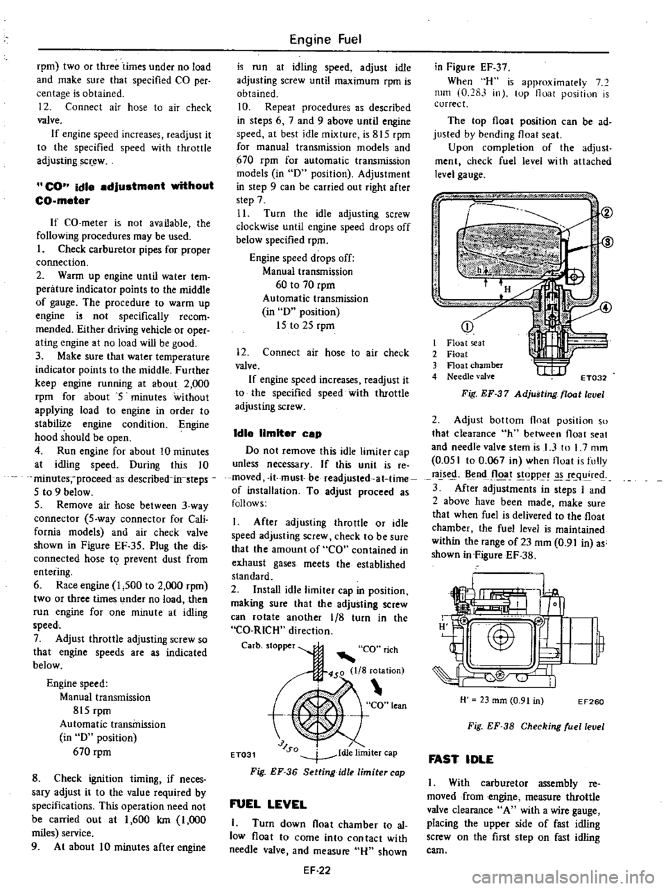
Carbo
to
per
CO
rich
450
lIS
rotation
t
CO
lean
J
SQ
dl
lim
ET031
1
e
Iter
cap
Fig
EF
36
Setting
idle
limiter
cap
FUEL
LEVEL
1
Turn
down
float
chamber
to
al
low
float
to
come
into
contact
with
needle
valve
and
measure
Hu
shown
EF
22
in
Figu
re
EF
37
When
H
is
approximalely
7
mill
0
283
in
lOp
float
position
is
correct
The
top
float
position
can
be
ad
justed
by
bending
float
seat
Upon
completion
of
the
adjust
ment
check
fuel
level
wi
th
attached
level
gauge
p
j
i
I
it
I
Float
seat
2
Float
3
Float
chamber
4
Needle
valve
t
I
IIf
ET032
Fig
EF
37
Adjusting
float
level
2
Adjust
bottom
float
position
so
that
clearance
h
between
float
seat
and
needle
valve
stemis
I
3
to
L
7
mm
0
051
to
0
067
in
when
Iloat
is
fully
rals
n
Jloa
t
goppe
q
re
3
After
adjustments
in
steps
I
and
2
above
have
been
made
make
sure
that
when
fuel
is
delivered
to
the
float
chamber
the
fuel
level
is
maintained
within
the
range
of23
mm
0
91
in
as
shown
in
FigureEF
38
H
23
mm
0
91
in
EF260
Fig
EF
38
Checking
ruellevel
FAST
IDLE
I
With
carburetor
assembly
reo
moved
from
engine
measure
throttle
valve
clearance
A
with
a
wire
gauge
placing
the
upper
side
of
fast
idling
screw
on
the
first
step
on
fast
idling
cam
Page 132 of 537
Engine
Fuel
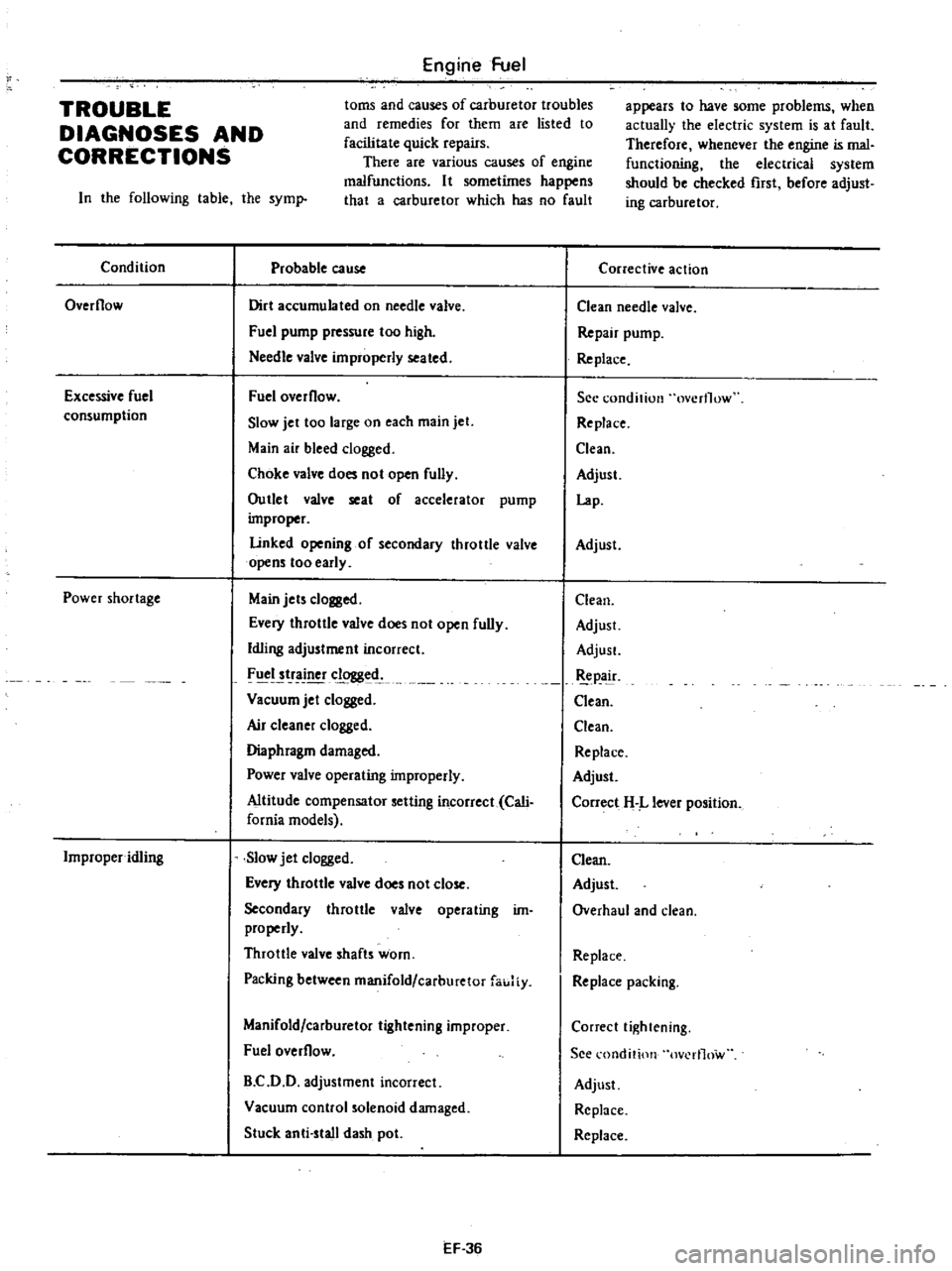
toms
and
causes
of
carburetor
troubles
and
remedies
for
them
are
listed
to
facilitate
quick
repairs
There
are
various
causes
of
engine
malfunctions
It
sometimes
happens
that
a
carburetor
which
has
no
fault
TROUBLE
DIAGNOSES
AND
CORRECTIONS
In
the
following
table
the
syml
Condition
Probable
cause
Overflow
Dirt
accumulated
on
needle
valve
Fuel
pump
pressure
too
high
Needle
valve
improperly
seated
Excessive
fuel
consumption
Fuel
overflow
Slow
jet
too
large
on
each
main
jet
Main
air
bleed
clogged
Choke
valve
does
not
open
fully
Outlet
valve
seat
of
accelerator
pump
improper
Linked
opening
of
secondary
throttle
valve
opens
too
early
Power
shortage
Main
jets
clogged
Every
throttle
valve
does
not
open
fully
Idling
adjustment
incorrect
FIICI
tr
clogged
Vacuum
jet
clogged
Air
c1eane
clogged
Diaphragm
damaged
Power
valve
operating
improperly
Altitude
compensator
setting
incorrect
Cali
fornia
models
Improper
idling
Slow
jet
clogged
Every
throttle
valve
does
not
close
Secondary
throttle
valve
operating
im
properly
Throttle
valve
shafts
worn
Packing
between
manifold
carburetor
fauJiy
Manifold
carburetor
tightening
improper
Fuel
overflow
B
C
D
D
adjustment
incorrect
Vacuum
control
solenoid
damaged
Stuck
anti
stall
dash
pot
EF
36
appears
to
have
some
problems
when
actually
the
electric
system
is
at
fault
Therefore
whenever
the
engine
is
mal
functioning
the
electrical
system
should
be
checked
rust
before
adjust
ing
carburetor
Corrective
action
Clean
needle
valve
Repair
pump
Re
place
See
condition
overflow
Replace
Clean
Adjust
Lap
Adjust
Clean
Adjust
AdjusL
pa
ir
Clean
Clean
Replace
Adjust
Correct
H
L
lever
position
Clean
Adjust
Overhaul
and
clean
Replace
Replace
packing
Correct
tightening
See
l
ondition
ov
rl1ow
Adjust
Replace
Replace
Page 312 of 537
Automatic
Transmission
TROUBLE
DIAGNOSIS
AND
ADJUSTMENT
INSPECTION
AND
ADJUSTMENT
BEFORE
TRQUBLE
DIAGNOSIS
TESTING
INSTRUMENT
FOR
INSPECTION
CHECKING
OIL
LEVEL
INSPECTION
AND
REPAIR
OF
OIL
EAKAGE
CHECKING
ENGINE
IDLING
REVOLUTION
CHECKING
AND
ADJUSTING
KICKDOWN
SWITCH
AND
DqWNSHIFT
SOLENOID
N
J
J
CII
Q
t
L
8li
p
JYSTMs
T
OF
MANUAL
LINKAGE
CHECKING
AND
ADJUSTING
INHIBITOR
SWITCH
STALL
TEST
STALL
TEST
PROCEDURES
JUDGEMENT
Since
most
automatic
transmission
troubles
can
be
repaired
by
simple
adjustment
do
not
disassemble
im
mediately
Firstly
inspect
and
adjust
the
auto
matic
transmission
in
place
utilizing
the
Trouble
Shooting
Chart
If
the
trouble
can
not
be
solved
by
this
procedure
remove
and
disas
semble
the
automatic
transmission
It
is
advisable
to
check
overhaul
and
repair
each
part
in
the
order
listed
in
the
Trouble
Shooting
Chart
I
In
the
Trouble
Shooting
Chart
the
diagnosis
items
are
arranged
ac
cording
to
difficulty
from
easy
to
difficult
therefore
please
follow
these
items
The
transmission
should
not
be
removed
unless
necessary
2
Tests
and
adjustments
should
be
made
on
the
basis
of
standard
values
and
the
data
should
be
recorded
INSPECTION
AND
ADJUSTMENT
BEFORE
TROUBLE
DIAGNOSIS
TESTING
INSTRUMENT
FOR
INSPECTION
I
Engine
tachometer
2
Vacuum
gauge
ROAD
TEST
VEHICLE
SPEED
AT
GEAR
SHIFT
CHECKING
SPEED
CHANGING
CONDITION
CHECKING
ITEMS
DURING
SPEED
CHANGE
SHIFT
SCHEDULE
LINE
PRESSURE
TEST
LINE
PRESSURE
governor
feed
pressure
JUDGEMENT
IN
MEASURING
LINE
PRESSURE
At
49
TR6
uBLE
SHOOTINC
CHART
INSPECTING
ITEMS
TROUBLE
SHOOTING
CHART
FOR
3N71B
AUTOMATIC
TRANSMISSION
TROUBLE
SHOOTING
GUIDE
FOR
3N71B
AUTOMATIC
TRANSMISSION
CONTENTS
AT
4B
AT
48
AT
4B
AT
49
AT
49
AT
49
AT
49
AT
50
AT
50
AT
50
3
Oil
pressure
gauge
It
is
convenient
to
install
these
instruments
in
a
way
that
allows
meas
urements
to
be
made
from
the
driver
s
seat
CHECKING
OIL
LEVEL
In
checking
the
automatic
transmis
sion
the
o
illevel
and
the
condition
of
oil
around
the
oil
level
gauge
should
be
examined
This
is
an
easy
and
effective
trouble
shooting
procedure
since
some
changes
in
oil
condition
are
often
linked
with
developed
troubles
For
instance
Lack
of
oil
causes
faulty
operation
by
making
the
clutches
and
brakes
slip
resulting
in
severe
wear
This
is
because
the
oil
pump
sucks
air
causing
oil
foaming
thus
rapidly
deteriorating
the
oil
quality
and
pro
ducing
sludge
and
varnish
Excessive
oil
is
also
bad
because
of
oil
foaming
caused
by
the
gears
stirring
up
the
oil
During
high
speed
driving
excessive
oil
in
the
transmission
often
blows
out
from
the
breather
Measuring
011
level
To
check
the
fluid
level
start
the
engine
and
run
it
until
normal
operat
T
AO
AT
51
AT
51
AT
52
AT
52
AT
52
AT
52
AT
53
AT
3
AT
53
AT
53
AT
54
AT
57
ing
temperatures
o
temperature
SO
to
800C
122
to
l760F
Approxi
mately
ten
minute
of
operation
will
raise
the
temperature
to
this
range
and
engine
idling
conditions
are
stabi
lized
Then
apply
the
brakes
and
move
the
transmission
shift
lever
through
all
drive
positions
and
place
it
in
park
P
position
In
this
inspec
tion
the
car
must
be
placed
on
a
level
surface
The
amount
of
the
oil
varies
with
the
temperature
As
a
rule
the
oil
level
must
be
measured
after
its
temper
ture
becomes
sufficiently
high
1
Fill
the
oil
to
the
line
H
The
difference
of
capacities
between
both
H
and
L
is
approximately
0
4
liter
Ji
V
S
p
Y
Imp
pl
and
therefore
do
not
to
fill
beyond
the
line
H
2
When
topping
up
and
changing
oil
care
should
be
taken
to
prevent
mixing
the
oil
with
dust
and
water
InspectIng
011
condition
The
condition
of
oil
sticking
to
the
level
gauge
indicates
whether
to
over
haul
and
repair
the
transmission
or
look
for
the
faulty
part
If
the
oil
has
deteriorated
to
a
varnish
ike
quality
it
causes
the
con
trol
valve
to
stick
Blackened
oil
indi
cates
a
burned
clutch
brake
band
etc
Page 314 of 537
Using
the
tester
check
the
two
black
yellow
BY
wires
from
the
in
hibitor
switch
in
the
ranges
N
and
I
and
the
tw
re
d
black
RBj
wir
s
in
the
range
R
for
continuity
Turn
range
select
lever
in
both
directions
from
each
lever
set
position
and
check
each
continuity
range
It
is
normal
if
the
electricity
is
on
while
the
lever
is
within
an
angle
of
about
30
on
both
sides
from
each
lever
set
line
How
ever
if
its
continl
ity
range
is
obvious
ly
unequal
on
both
sides
adjustment
is
required
If
any
malfunction
is
found
un
screw
the
fastening
nut
of
the
range
selector
lever
and
two
fastening
bolts
of
the
switch
body
and
then
remove
the
machine
screw
under
the
switch
body
Adjust
the
manual
shaft
correct
ly
to
the
position
N
by
means
of
the
selector
lever
When
the
slot
of
the
shaft
becomes
vertical
the
detent
works
to
position
the
shaft
correctly
with
a
clicking
sound
MSlVe
the
switch
slightly
asj
Je
so
that
the
screw
hole
will
be
aligned
with
the
pin
hole
of
the
internal
rotor
combined
with
the
manual
shaft
and
check
their
alignment
by
inserting
a
1
5
mm
0
059
in
diameter
pin
into
the
holes
If
the
alignment
is
correct
fasten
the
switch
body
with
the
bolts
pull
out
the
pin
tighten
up
the
screw
in
the
hole
and
fasten
the
selector
lever
as
before
Check
the
continuity
again
with
the
tester
If
the
malfunc
tion
still
remains
replace
the
inhibitor
switch
Chcck
whether
the
reverse
lamp
and
the
starter
motor
operate
normal
ly
in
these
ranges
If
Ihere
is
any
lrouble
first
check
the
linkage
If
no
fault
is
found
in
the
linkage
check
the
inhibitor
switch
Separate
the
manual
lever
from
Ihe
remote
control
selector
rod
and
turn
the
range
selcct
lever
to
N
Note
In
the
position
N
the
slot
of
the
manual
shaft
is
vertical
STALL
TEST
The
purpose
of
this
test
is
to
check
the
transmission
and
engine
for
trou
ble
by
measuring
the
maximum
num
bers
of
revolutions
of
the
engine
while
Automatic
Transmission
vehicle
is
held
in
a
stalled
condition
The
carburctor
is
in
full
throttle
opera
tion
with
the
selector
lever
in
ranges
f
2
and
I
respectively
Com
pare
the
measured
results
with
the
slandard
values
Components
to
be
tested
and
test
items
I
Clutches
brake
and
band
in
trans
mission
for
slipping
2
Torque
converter
for
proper
fune
tioning
3
Engine
for
overall
properly
STALL
TEST
PROCEDURES
Before
Icsting
c
heck
the
engine
oil
and
torque
converter
oil
warm
up
the
engine
cooling
water
to
suitable
tem
perature
by
running
at
1
200
rpm
with
the
selector
lever
in
the
range
P
for
several
minutes
Warm
up
the
torque
converter
oil
to
suitable
temperature
6010
1000C
140
to
2l20F
I
Mount
the
engine
tachometer
at
a
location
that
allows
good
visibility
fro
the
dri
er
s
seat
and
put
a
mark
on
specified
revolutions
on
the
meter
2
Secure
the
front
and
rear
wheels
with
chocks
and
apply
the
hand
brake
Be
sure
to
depress
the
brake
pedal
fumly
with
the
left
foot
before
de
pressing
the
accelerator
pedal
3
Throw
the
selector
lever
into
the
range
1
4
Slowly
depress
the
accelerator
pedal
until
the
throttle
valvc
is
fully
opened
Quickly
read
and
record
the
engine
revolution
when
the
engine
begins
to
rotate
steadily
and
then
release
the
accelerator
pedal
5
Shift
the
selector
lever
to
N
and
operate
the
engine
at
approxi
mately
1
200
rpm
for
more
than
one
minute
to
cool
down
the
torque
con
ver
ter
oil
and
coolant
6
Make
similar
stall
tests
in
ranges
2
I
and
RIO
Note
The
stall
test
operation
as
speci
f
d
in
item
4
should
be
I
l3de
wiihin
five
seconds
If
it
takes
too
long
the
oil
deteriorates
an
the
clutches
brake
and
band
are
ad
versely
affected
Sufficient
cooling
time
should
be
given
between
each
AT
5O
test
for
the
four
ranges
0
2
I
and
R
JUDGEMENT
High
stall
revolution
more
than
standard
revolution
If
the
engine
revolution
in
stall
condition
is
higher
than
the
standard
values
it
indicates
that
one
or
more
clutches
in
the
transmission
are
slipping
and
therefore
no
further
test
is
required
For
the
following
abnormalities
the
respective
causes
are
presumed
High
rpm
in
all
ranges
low
Iine
pressure
High
rpm
in
D
2
and
I
and
normal
rpm
in
R
Rear
clutch
slipping
High
rpm
in
0
and
normal
rpm
in
I
clutch
slipping
High
rpm
in
R
only
Front
clutch
or
low
and
reverse
brake
slipping
To
determine
which
is
slipping
front
clutch
or
low
and
reverse
brake
a
road
test
is
nceded
If
whilc
coasting
after
starting
with
the
lever
in
1
range
engine
braking
does
not
work
properly
the
low
and
reverse
brake
is
slipping
Otherwise
the
front
clutch
is
slipping
Slipping
of
the
band
brake
is
diffi
cult
to
ascertain
However
if
it
occurs
with
the
lever
in
2
range
engine
revolution
increases
Jp
to
thesarne
level
as
in
I
strange
It
is
impossible
to
check
it
in
the
stall
test
2
and
One
way
2
Standard
stall
revolution
If
the
engine
revolution
in
stall
condition
is
within
the
standard
values
the
control
elements
are
nor
mally
operating
in
the
ranges
0
2
I
and
R
Also
tIle
engine
and
one
way
clutch
of
the
torque
converter
are
normal
in
performance
and
operation
The
one
way
clutch
of
the
torque
converter
however
sometimes
sticks
This
is
determined
in
the
road
test
3
Lower
stall
revolution
than
stand
ard
revolution
If
the
engine
revolution
in
stall
condition
is
lower
than
the
standard
Page 336 of 537
PROPElli
ER
SHAfT
DIFFERENTIAL
G
ARRIERf
Notes
a
PUller
should
be
handled
with
care
in
catchins
the
edge
of
bearing
inner
race
b
Be
careful
not
to
confuse
left
and
right
hand
parts
2
Remove
ring
gear
by
spreading
out
lock
strap
and
loosening
ring
gear
bolts
in
diagonally
3
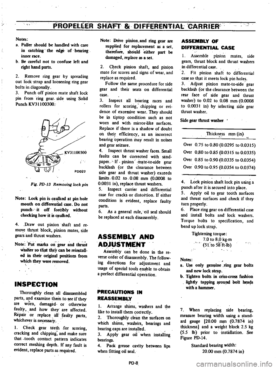
Punch
off
pinion
mate
shaft
lock
pin
from
ring
gear
side
using
Solid
Punch
ICV31100300
KV31100300
PD022
Fig
PD
13
Removing
lock
pin
Note
Lock
pin
i
cauIked
at
pin
hole
mouth
on
differential
case
Do
not
punch
it
off
forCibly
without
checkins
how
it
is
uIked
4
Draw
out
pinion
shaft
and
re
move
thrust
block
pinion
mates
side
gears
and
thrust
washers
Note
Put
marks
on
gear
and
thrust
Wasliersotliat
they
can
be
reinstaD
ed
in
their
original
positions
from
which
they
were
removed
INSPECTION
Thoroughly
clean
all
disassembled
parts
and
examine
them
to
see
if
they
8re
worn
damaged
or
otherwise
faulty
and
how
they
are
affected
Repair
or
replace
ail
faulty
parts
whichever
is
necessaiy
I
Check
gear
teeth
for
scoring
cracking
and
chipping
and
make
sure
that
tooth
contact
pattern
indicates
correct
meshing
depth
If
any
fault
is
evident
replace
parts
as
required
Note
Drive
pinion
and
ring
gear
are
supplied
for
replacement
as
a
set
therefore
should
either
part
be
damaged
replace
as
a
set
2
Check
pinion
shaft
and
pinic
m
mate
for
scores
and
signs
of
wear
and
replace
as
required
Follow
the
same
procedure
for
side
gear
and
their
seats
on
differential
case
3
Inspect
all
bearing
races
and
rollers
for
scoring
chipping
or
evi
dence
of
excessive
wear
They
should
be
in
tiptop
condition
such
as
not
worn
and
with
mirror
like
surfaces
Replace
if
there
is
a
shadow
of
doubt
oil
their
efficiency
as
an
incorrect
bearing
operation
may
result
in
noises
and
gear
seizure
4
Inspect
thrust
washer
faces
Small
faults
can
be
corrected
with
sand
paper
If
pinion
mate
to
ide
gear
backlash
or
the
clearance
between
side
gear
and
thrust
washer
exceeds
limits
0
02
to
0
08
nun
0
0008
to
0
0031
in
replace
thrust
washers
S
Inspect
carrier
and
differential
case
for
cracks
or
distortion
If
either
condition
is
evident
replace
faulty
parts
6
As
a
general
rule
oil
seal
should
be
replaced
at
each
disassembly
ASSEMBLY
AND
ADjUSTMENT
Assembly
can
be
done
in
the
reo
verse
order
of
disassembly
The
foDow
ing
directions
for
adjustment
and
usage
of
special
tools
enable
to
obtain
a
perfect
differential
operation
PRECAUTIONS
IN
REASSEMBLY
I
Arrange
shims
w
shers
and
the
like
to
install
them
correctly
2
Thoroughly
clean
the
surfaces
on
which
shims
washers
bearings
and
bearing
caps
are
installed
3
Apply
gear
oil
when
installing
bearings
4
Pack
grease
cavity
between
lips
when
fitting
oil
seal
PD
8
ASSEMBLY
OF
DIFFERENTIAL
CASE
I
Assemble
pinion
mates
side
gears
thrust
block
and
thrust
washers
in
differential
case
2
Fit
pinion
shaft
to
differential
case
so
that
it
meets
lock
pin
holes
3
Adjust
pinion
mate
to
ide
gear
backlash
or
the
clearance
between
the
rear
face
of
side
gear
and
thrust
washer
to
0
02
to
0
08
mOl
0
0008
to
0
0031
in
by
selecting
side
gear
thrust
washer
Side
gear
thrust
WlISber
Thickness
nun
in
Over
0
7S
to
0
80
0
029S
to
0
03IS
Over
0
80
to
O
8S
Om
IS
to
0
033S
Over
0
8S
to
0
90
0
033S
to
0
03S4
Over
0
90
to
0
9S
0
03S4
to
0
0374
4
Lock
pinion
shaft
lock
pin
using
a
punch
after
it
is
secured
into
place
S
Apply
oil
to
gear
tooth
surfaces
and
thrust
surfaces
and
check
if
they
turn
properly
6
Place
ring
gear
on
differential
case
and
install
bolts
and
lock
washers
Torque
bolts
to
specification
and
bend
up
lock
strap
Tightening
torque
7
0
to
8
0
kg
m
S1to
Sifft
Ib
Notes
ao
Use
only
genuine
ring
gear
bolts
and
new
lock
strap
b
Tighten
bolts
in
criss
cross
fashion
lighdy
tapping
fOund
bolt
heac
Js
with
a
hammer
7
When
replacing
side
bearing
measure
bearing
width
using
a
stand
ard
gauge
20
00
nun
0
7874
in
thickness
and
a
weight
block
2
5
kg
S
S
Ib
prior
to
installation
See
Figure
PD
I4
Standard
bearing
width
20
00
nun
0
7874
in
Page 353 of 537

spindle
and
torque
bolt
to
10
3
to
12
1
kg
m
75
to
88
ft
lb
Bend
lock
plate
to
engaged
flats
on
boll
head
Note
When
disassembled
discard
used
lock
plate
5
Pack
grea
to
the
upP
r
and
lower
bushings
on
knuckle
spindle
until
grease
c
omes
out
from
gr
ease
seal
6
Fill
wheel
hub
and
cap
with
grease
up
to
the
described
level
See
Figure
F
A
4
FA141
Fig
FA
4
Gre
ing
wheel
hub
7
Pack
roller
and
cone
assembly
and
the
cavity
of
grease
seal
lip
with
grease
8
Coat
grease
to
the
thread
of
knuckle
spindle
bearing
washer
and
bearing
lock
nul
9
Secure
wheel
hub
bearings
bear
ing
washer
and
spindle
nut
on
knuckle
spindle
and
adju
t
bearing
preload
referring
to
the
paragraph
Wheel
bearing
adjustment
Note
Be
sure
to
obtain
correct
pre
load
on
wheel
bearings
for
the
pu
rpose
of
ving
their
long
life
taking
care
to
keep
wheel
be8rlngs
grease
seal
bearing
washer
and
spin
dle
nut
clean
when
installing
them
WHEEL
BEARING
D
TM
NT
Wrong
adjustment
of
wheel
bear
ing
causes
abnonnal
wear
and
score
on
the
bearings
and
knuckle
spindle
Front
Axle
Front
Suspension
To
attain
proper
preload
on
wheel
bearings
proceed
the
following
opera
tions
I
Torque
spindle
nut
to
3
0
to
3
S
kg
m
22
to
25
ft
lb
using
torque
wrench
FA227
Fig
FA
5
Tightening
apindle
nut
2
Rotate
wheel
hub
a
few
turns
clockwise
and
counterclockwise
to
seat
bearings
Then
retighten
spindle
nut
to
the
same
tightening
torque
Be
certain
to
rotate
hub
smoothly
3
Back
off
spindle
nut
in
range
from
40
to
70
degrees
Locate
adjust
ing
cap
on
spindle
nut
so
as
to
align
the
castellation
on
the
cap
with
the
cotter
pin
hole
in
the
spindle
4
Check
the
hub
rotation
If
hub
rotates
properly
measure
bearing
rota
tion
starting
torque
If
measured
torque
is
deviated
from
the
specified
value
r
place
beari
gs
r
re
dju
st
The
starting
torque
can
be
mea
sured
by
a
spring
balance
as
shown
in
Figure
F
A
6
Spring
balance
indication
at
hub
bolt
New
bearing
2
1
kg
4
Ib
o
ess
Used
bearing
1
0
kg
2
2
lb
or
less
Notes
a
When
measuring
the
starting
force
pull
the
spring
balance
toward
tan
gential
direction
against
normal
line
connected
between
hub
boll
and
spindle
center
b
Axial
play
is
permissible
to
exist
in
0
1
mm
0
004
in
or
less
FA
4
fA22S
Fig
FA
6
Mea
uring
bearing
rotation
atarting
torque
S
Install
a
new
cotter
pin
Bend
the
ends
of
coller
pin
around
the
castel
lated
flange
of
adjusting
cap
Then
install
hub
cap
DISASSEMBLY
AND
ASSEMBLY
Knuckle
spindle
I
Drive
spindle
bushing
and
grease
seal
out
of
knuckle
spindle
with
KiTlg
Pin
Bush
Drift
ST3S380000
Discard
bushing
and
grease
seal
when
disas
sembled
2
After
cleaning
king
pin
bores
thoroughly
install
bushing
carefully
by
using
the
above
special
tpol
Posi
tion
bushing
in
accordance
With
the
instructions
fIlled
in
Figure
F
A
7
and
FA
8
34
mm
1
34
in
Upper
side
in
lower
boss
I
I
1
II
I
Pla
ce
this
position
in
line
with
grease
nipple
hole
Upper
side
in
upper
boss
FA229
Fig
FA
7
King
pin
bu
hing
Page 387 of 537
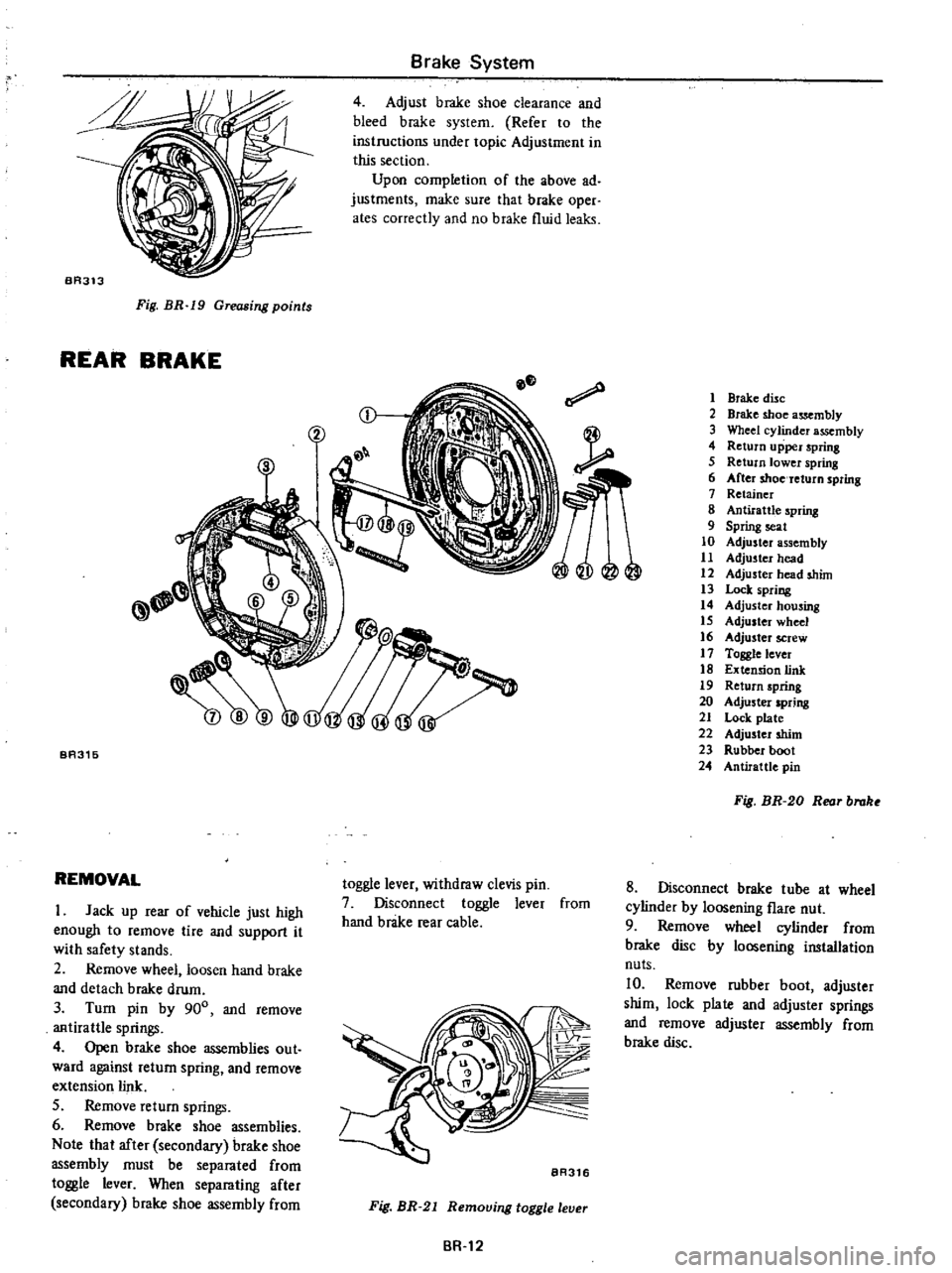
BA313
Fig
BR
19
Greasing
points
REAR
BRAKE
Brake
System
4
Adjust
brake
shoe
clearance
and
bleed
brake
system
Refer
to
the
instructions
under
topic
Adjustment
in
this
section
Upon
completion
of
the
above
ad
justments
make
sure
that
brake
oper
ates
correctly
and
no
brake
fluid
leaks
BA315
REMOVAL
I
Jack
up
rear
of
vehicle
just
high
enough
to
remove
lire
and
support
it
with
safety
stands
2
Remove
wheel
loosen
hand
brake
and
detach
brake
drum
3
Turn
pin
by
900
and
remove
antirattle
springs
4
Open
brake
shoe
assemblies
out
ward
against
return
spring
and
remove
extension
link
S
Remove
return
springs
6
Remove
brake
shoe
assemblies
Note
that
after
secondary
brake
shoe
assembly
must
be
separated
from
toggle
lever
When
separating
after
secondary
brake
shoe
assembly
from
toggle
lever
withdraw
clevis
pin
7
Disconnect
toggle
lever
from
hand
brake
rear
cable
BR316
Fig
BR
21
Remouing
toggle
leuer
BR
12
1
Brake
disc
2
Brake
shoe
assembly
3
Wheel
cylinder
assembly
4
Return
upper
spring
5
Return
lower
spring
6
After
shoe
return
spring
7
Retainer
8
Antirattle
spring
9
Spring
seat
10
Adjuster
assembly
11
Adjuster
head
12
Adjuster
head
shim
13
Lock
spring
14
Adjuster
housing
15
Adjuster
wheel
16
Adjuster
screW
17
Toggle
lever
18
Extension
link
19
Return
spring
20
Adjuster
spring
21
Lock
plate
22
Adjuster
shim
23
Rubber
boot
24
Antirattlc
pin
Fig
BR
20
Reor
brake
8
Disconnect
brake
tube
at
wheel
cylinder
by
loosening
flare
nut
9
Remove
wheel
cylinder
from
brake
disc
by
loosening
installation
nuts
10
Remove
rubber
boot
adjuster
shim
lock
plate
and
adjuster
springs
and
remove
adjuster
assembly
from
brake
disc