steering wheel DATSUN PICK-UP 1977 Owner's Manual
[x] Cancel search | Manufacturer: DATSUN, Model Year: 1977, Model line: PICK-UP, Model: DATSUN PICK-UP 1977Pages: 537, PDF Size: 35.48 MB
Page 441 of 537

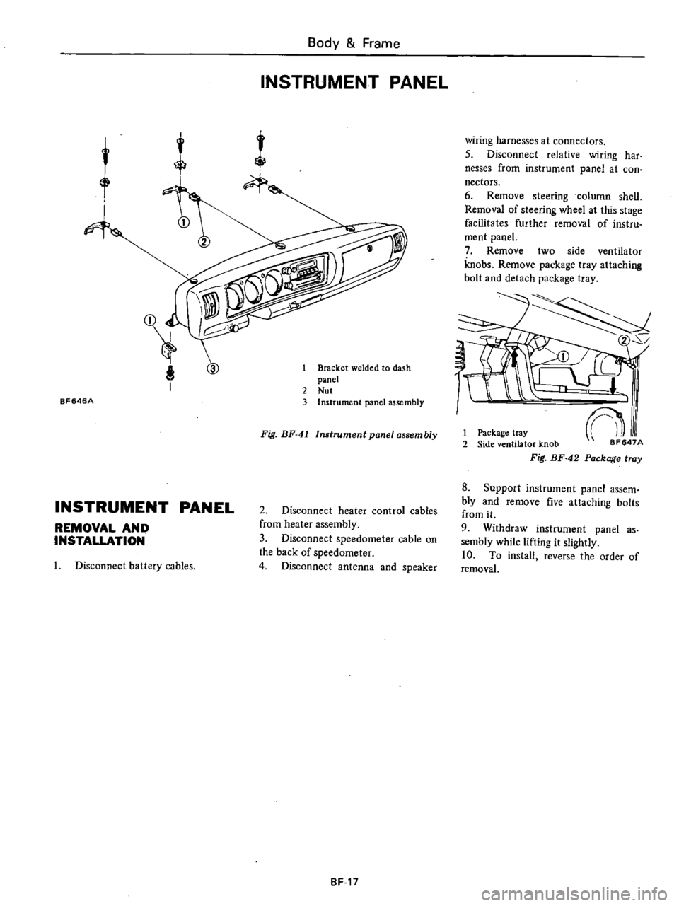
BF646A
Body
Frame
INSTRUMENT
PANEL
1
Bracket
welded
to
dash
panel
2
Nut
3
Instrument
panel
assembly
Fig
BF
41
Instrument
panel
assembly
INSTRUMENT
PANEL
REMOVAL
AND
INSTALLATION
2
Disconnect
heater
control
cables
from
heater
assembly
3
Disconnect
speedometer
cable
on
the
back
of
speedometer
4
Disconnect
antenna
and
speaker
Disconnect
battery
cables
8F
17
wiring
harnesses
at
connectors
5
Disconnect
relative
wiring
har
nesses
from
instrument
panel
at
con
nectors
6
Remove
steering
column
shell
Removal
of
steering
wheel
at
this
stage
facilitates
further
removal
of
instru
ment
panel
7
Remove
two
side
ventilator
knobs
Remove
package
tray
attaching
bolt
and
detach
package
tray
2
I
Package
tray
2
Side
ventilator
knob
Fig
BF
42
Package
tray
8
Support
instrument
panel
assem
bly
and
remove
five
attaching
bolts
from
it
9
Withdraw
instrument
panel
as
sembly
while
lifting
it
slightly
10
To
install
reverse
the
order
of
removal
Page 455 of 537

KNOB
ILLUMINATION
LAMP
The
illumination
lamp
is
located
on
the
illumination
control
rheostat
This
lamp
illuminates
the
knob
of
the
wiper
switch
and
lighting
switch
with
fiberscopes
The
fiberscopes
between
the
knobs
and
cap
of
the
illumination
lamp
carry
the
light
through
their
tubes
with
the
inner
reflective
walJ
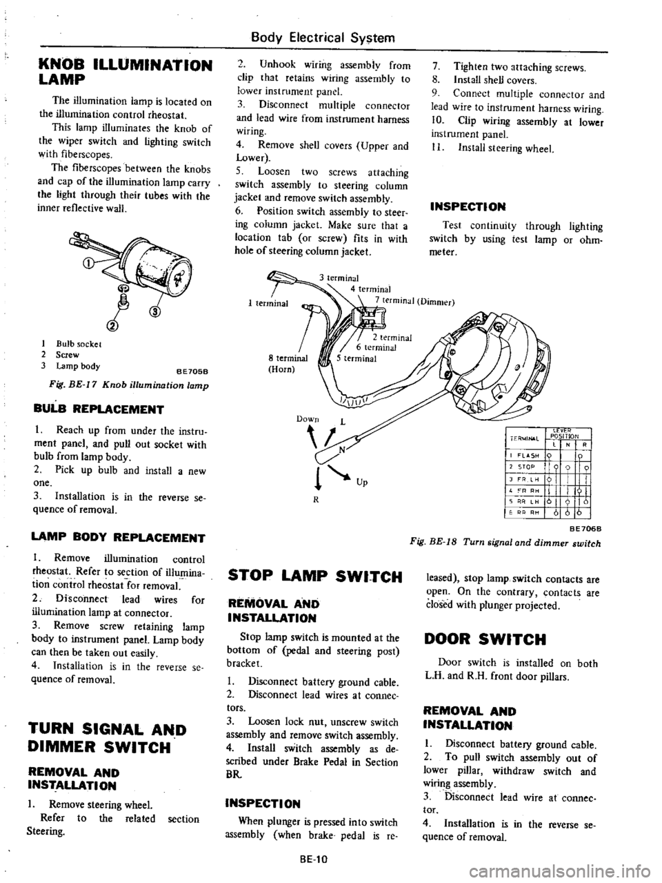
CID
1
Bulb
socket
2
Screw
3
Lamp
body
8E705B
Fig
BE
17
Knob
illumination
lamp
BULB
REPLACEMENT
I
Reach
up
from
under
the
instru
ment
panel
and
pull
out
socket
with
bulb
from
lamp
body
2
Pick
up
bulb
and
install
a
new
one
3
Installation
is
in
the
reverse
se
quence
of
removal
LAMP
BODY
REPLACEMENT
1
Remove
illumination
control
rheostat
Refer
to
section
of
illumina
ti
on
control
rheostat
for
removal
2
Disconnect
lead
wires
for
illumination
lamp
at
connector
3
Remove
screw
retaining
lamp
body
to
instrument
panel
Lamp
body
can
then
be
taken
out
easily
4
Installation
is
in
the
reverse
se
quence
of
removal
TURN
SIGNAL
AND
DIMMER
SWITCH
REMOVAL
AND
INSTALLATION
I
Remove
steering
wheel
Refer
to
the
related
section
Steering
Body
Electrical
System
2
Unhook
wiring
assembly
from
clip
that
retains
wiring
assembly
to
lower
instrument
panel
3
Disconnect
multiple
connector
and
lead
wire
from
instrument
harness
wiring
4
Remove
shell
covers
Upper
and
Lower
5
Loosen
two
screws
attaching
switch
assembly
to
steering
column
jacket
and
remove
switch
assembly
6
Position
switch
assembly
to
steer
ing
column
jacket
Make
sure
that
a
location
tab
or
screw
fits
in
with
hole
of
steering
column
jacket
7
Tighten
two
attaching
screws
8
Install
shell
covers
9
Connect
multiple
connector
and
lead
wire
to
instrument
harness
wiring
10
Clip
wiring
assembly
at
lower
instrument
panel
II
Install
steering
wheel
INSPECTION
Test
continuity
through
lighting
switch
by
using
test
lamp
or
ohm
meter
3
terminal
4
terminal
7
terminal
Dimmer
R
STOP
LAMP
SWITCH
REMOVAL
AND
INSTALLATION
Stop
lamp
switch
is
mounted
at
the
bottom
of
pedal
and
steering
post
bracket
I
Disconnect
battery
ground
cable
2
Disconnect
lead
wires
at
coonee
tors
3
Loosen
lock
nut
unscrew
switch
assembly
and
remove
switch
assembly
4
Install
switch
assembly
as
de
scribed
under
Brake
Pedal
in
Section
BR
INSPECTION
When
plunger
is
pressed
into
switch
assembly
when
brake
pedal
is
reo
8El0
I
Ll
vt
r
I
ER
4JN
l
L
PlOSITlON
RI
j
LASH
n
I
I
12
STOP
9
91
I
JFRe
I
I
II
L
I
III
11
I
I
II
161
I
61616
BE706B
Fig
BE
IS
Turn
signal
and
dimmer
switch
leased
stop
lamp
switch
contacts
are
open
On
the
contrary
contacts
are
closed
with
plunger
projected
DOOR
SWITCH
Door
switch
is
installed
on
both
L
H
and
R
H
front
door
pillars
REMOVAL
AND
INSTALLATION
I
Disconnect
battery
ground
cable
2
To
pull
switch
assembly
out
of
lower
pillar
withdraw
switch
and
wiring
assembly
3
Disconnect
lead
wire
at
cannee
tor
4
Installation
is
in
the
reverse
se
quence
of
removal
Page 534 of 537

Service
Equipment
Applied
Ser
77
620NA
Newly
No
Tool
Number
Tool
Name
vehicle
Class
Remarks
added
or
unit
KVOO
102000
ST31970000
Collar
All
X
2
610
ST30611000
Drive
pinion
outer
race
drift
bar
All
X
2
610
ST30613000
Drive
pinion
outer
race
drift
adapter
All
X
2
610
ST3062
1000
Drive
pinion
outer
race
drift
adapter
All
X
2
610
KV311
00300
Solid
punch
All
X
2
610
710
S30
ST3127S000
Preload
gauge
All
X
2
B21O
610
710
S30
KV381025S0
Oil
seal
fitting
tool
All
X
2
610
4
Front
axle
ST35380000
Kingpin
bushing
drift
All
X
2
HT56802000
Kingpin
bushing
reamer
All
X
2
ST36070000
Transverse
link
bushing
replacer
All
X
2
ST35390000
Kingpin
grease
seal
drift
All
X
2
5
Rear
axle
ST38020000
Bearing
lock
nut
wrench
All
X
2
KV40101000
Rear
axle
stand
All
X
2
B210
610
710
S30
ST36230000
Sliding
hammer
All
X
5
B210
610
710
S30
HT72480000
Rear
axle
shaft
bearing
puller
All
X
2
B210
610
710
S30
6
Steering
ST2902000
I
Pitman
arm
puller
All
X
2
B210
610
710
S30
ST27
180001
Steering
wheel
puller
All
X
2
FIO
B210
610
710
S30
HT72520000
Ball
joint
remover
All
X
2
FIO
B210
610
710
S30
ST3127S000
Preload
gauge
All
X
FlO
B210
610
710
S30
7
Brake
GG943
10000
Brake
pipe
torque
wrench
All
X
2
B210
610
710
S30
ST08060000
Master
Vac
oil
seal
retainer
drift
All
X
3
B210
610
710
S30
ST08080000
Master
Vac
wrench
All
X
3
B210
610
710
S30
SE
5