wheel torque DATSUN PICK-UP 1977 Owner's Guide
[x] Cancel search | Manufacturer: DATSUN, Model Year: 1977, Model line: PICK-UP, Model: DATSUN PICK-UP 1977Pages: 537, PDF Size: 35.48 MB
Page 393 of 537
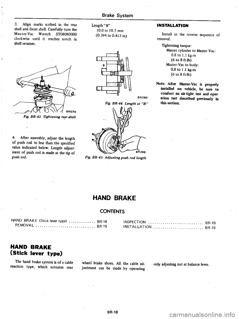
3
Align
marks
scribed
in
the
rear
shell
and
front
shell
Carefully
turn
the
Master
Vac
Wrench
ST08080000
clockwise
until
it
reaches
notch
in
shell
retainer
Fig
BR
43
Tightenilll
reor
shell
4
After
assembly
adjust
the
length
of
push
rod
to
less
than
the
specified
value
indicated
below
Length
adjust
ment
of
push
rod
is
made
at
the
tip
of
push
rod
HAND
BRAKE
Stick
lever
typ
e
REMOVAL
HAND
BRAKE
Stick
lever
type
The
hand
brake
system
is
of
a
cable
reaction
type
which
actuates
rear
Brake
System
Length
B
10
0
to
10
5
mID
0
394
to
0
413
in
rl
J
BA290
Fig
BR
44
Lelll
th
at
B
Fig
BR
45
Adjusting
push
rod
length
HAND
BRAKE
CONTENTS
BR
18
BR
19
INSPECTION
INSTALLATION
wheel
brake
shoes
All
the
cable
ad
justment
can
be
made
by
operating
BR
18
INSTALLATION
Install
in
the
reverse
sequence
of
removal
Tightening
torque
Master
cylinder
to
Master
Vac
0
8
to
I
1
kg
m
6
to
8
ft
lb
Master
Vac
to
body
0
8
to
1
1
kg
m
6
to
8
ft
Ib
Note
After
Master
Vac
is
properly
installed
on
vehicle
be
sure
to
conduct
an
air
tight
test
and
oper
ation
test
described
previously
in
this
section
BR
19
BR
19
only
adjusting
nut
at
balance
lever
Page 396 of 537

Brake
System
Tightening
torque
Master
cylinder
to
Master
Vac
kg
m
ft
Ib
0
8
to
l
l
6
to
8
Brake
tube
flare
nut
kg
m
ft
Ib
I
S
to
1
8
II
to
13
Brake
hose
connector
kg
m
ft
lb
1
8
to
2
1
13
to
IS
Air
bleeder
valve
kg
m
ft
lb
0
7
to
0
9
S
to
7
Fulcrum
pin
of
brake
pedal
kg
m
ft
Ib
1
2
to
1
5
9
to
II
Connector
and
clip
fIXing
bolt
kg
m
ft
lb
0
35
to
O
4S
2
5
to
3
3
3
way
connector
fIXing
bolt
kg
m
ft
Ib
0
8
to
l
l
6
to
8
on
rear
axle
case
Brake
pedal
stopper
lock
nut
kg
m
ft
Ib
1
2
to
1
5
9
to
II
N
L
S
V
to
body
kg
m
ft
Ib
0
8
to
l
l
6
to
8
Wheel
cylinder
mounting
nut
Front
kg
m
ft
Ib
S
4
to
6
6
39
to
48
Rear
kg
m
ft
Ib
1
5
to
1
8
II
to
13
Wheel
cylinder
connector
bolt
kg
m
ft
lb
1
9
to
2
5
14
to
18
Brake
disc
Back
plate
nut
Front
kg
m
ft
Ib
4
2
to
S
O
30
to
36
Rear
kg
m
ft
Ib
S
4
to
6
4
39
to
46
Master
Vac
Master
Vac
to
body
nut
kg
m
ft
lb
0
8
to
l
l
6
to
8
Flange
to
shell
cover
nut
kg
m
ft
lb
0
8
to
1
1
6
to
8
Operating
rod
lock
nut
kg
m
ft
Ib
1
6
to
2
2
12
to
16
Push
rod
adjusting
nut
kg
m
ft
Ib
1
9
to
2
4
14
to
17
BR
21
Page 398 of 537

Condition
Brake
chatters
Brake
squeals
Pedal
pulsates
Brakes
fade
Brakes
drag
Unbalanced
brakes
Brake
System
Probable
cause
Groove
or
out
of
round
brake
drum
Loose
or
bent
brake
disc
Distorted
brake
shoes
or
pads
Grease
or
brake
fluid
on
linings
Dirty
or
scored
brake
drums
Distorted
brake
shoes
or
bent
support
plate
Weak
or
broken
brake
shoe
retaining
spring
or
return
spring
Glazed
or
contaminated
brake
lining
Out
of
round
or
off
center
drum
Brake
fluid
has
too
low
boiling
point
Use
of
improper
linings
or
brake
linings
are
contaminated
Brake
drums
are
out
of
round
Hydraulic
connections
master
cylinder
and
wheel
cylinders
are
corroded
or
damaged
Bleed
screw
is
open
Pedal
linkage
is
binding
or
push
rod
adjust
ment
is
too
long
Master
cylinder
compensator
part
is
ob
structed
Seized
master
cylinder
piston
Poor
shoe
condition
Poor
wheel
cylinder
condition
Deformation
of
piston
cups
Hand
brake
will
not
return
Clogged
master
cylinder
return
port
Improper
tire
inflation
Improper
adjustment
of
shoe
to
drum
clear
anee
Grease
oil
mud
or
water
on
linings
or
pads
Mud
in
brake
drum
Deterioration
of
linings
or
pads
Excessive
wear
of
linings
or
pads
BR
23
Corrective
action
Grind
or
replace
as
required
Tighten
support
plate
bolts
to
specified
torque
or
replace
plate
Replace
as
necessary
Replace
linings
Blowout
assembly
with
compressed
air
or
refinish
drum
Replace
faulty
unit
Replace
if
faulty
Cam
ground
lining
to
eliminate
glaze
If
it
doesn
t
replace
linings
Turn
drum
or
replace
as
necessary
Drain
and
fill
system
with
approved
fluid
Replace
linings
Repair
or
replace
as
necessary
Repair
as
necessary
Close
screw
and
bleed
system
Lubricate
linkage
check
pedal
return
spring
for
condition
and
adjust
push
rod
as
neces
sary
Blowout
foreign
matter
with
compressed
air
Disassemble
master
cylinder
and
replace
piston
Bleed
system
Clean
and
repair
Repair
or
replace
Replace
Check
and
repair
Clean
Inflate
to
correct
pressure
Readjust
Clean
brake
mechanism
and
check
for
cause
of
problem
Replace
linings
or
pads
Clean
Replace
Replace
Page 405 of 537

Condition
Wheel
wobbles
Unevenly
or
excessively
worn
tire
Tire
squeals
Wheel
and
Tire
TROUBLE
DIAGNOSES
AND
CORRECTIONS
Probable
cause
Improper
tire
pressure
Damaged
tire
or
distorted
wheel
rim
Unbalanced
wheel
Loose
wheel
nuts
Worn
or
damaged
wheel
bearing
or
excessive
play
of
wheel
bearing
Improper
front
wheel
alignment
Worn
or
damaged
ball
joint
Excessive
steering
linkage
play
or
worn
steering
linkage
Loose
steering
linkage
connection
Broken
suspension
spring
Damaged
shock
absorber
Improper
tire
rotation
Improper
tire
pressure
Unbalanced
wheel
Improperly
adjusted
brake
Improper
wheel
alignment
Excessively
distorted
or
improperly
installed
suspension
link
High
speed
on
curves
Sudden
start
and
improper
speed
due
to
rapid
acceleration
or
improper
brake
ap
plication
Improper
tire
pressure
Improper
front
wheel
alignment
Distorted
knuckle
or
suspension
link
WT
5
Corrective
action
Measure
and
adjust
Repair
or
replace
Balance
Tighten
Correct
play
or
replace
wheel
bearing
Align
Replace
Adjust
Or
replace
Tighten
nuts
to
rated
torque
or
replace
worn
parts
if
any
Replace
Replace
Conduct
tire
rotation
periodically
Measure
and
adjust
Balance
or
replace
Adjust
Align
Repair
replace
or
if
necessary
reinstall
Reduce
speed
Follow
correct
and
proper
driving
manner
Measure
and
adjust
Align
Repair
or
replace
Page 409 of 537
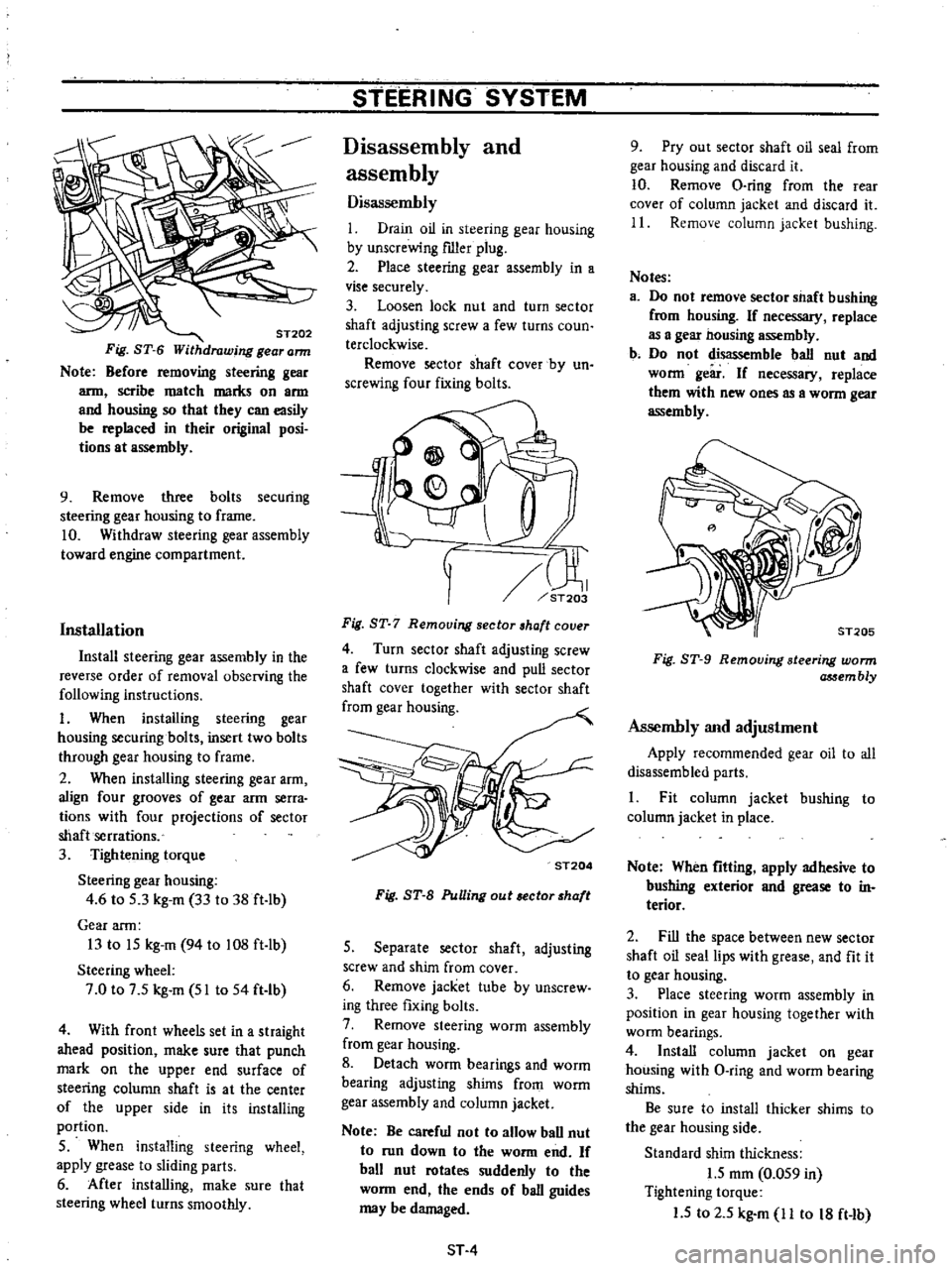
ST202
Fig
ST
6
Withdrawing
gear
ann
Note
Before
removing
steering
gear
arm
scribe
match
marks
on
arm
and
housing
so
that
they
can
easily
be
replaced
in
their
original
posi
tions
at
assembly
9
Remove
three
bolts
securing
steering
gear
housing
to
frame
10
Withdraw
steering
gear
assembly
toward
engine
compartment
Installation
Install
steering
gear
assembly
in
the
reverse
order
of
removal
observing
the
following
instructions
I
When
installing
steering
gear
housing
securing
bolts
insert
two
bolts
through
gear
housing
to
frame
2
When
installing
steering
gear
arm
align
four
grooves
of
gear
arm
serra
tions
with
four
projections
of
sector
shaft
serrations
3
Tightening
torque
Steering
gear
housing
4
6
to
S
3
kg
m
33
to
38
ft
lb
Gear
arm
13
to
IS
kg
m
94
to
108
ft
lb
Steering
wheel
7
0
to
7
S
kg
m
51
to
54
ft
Ib
4
With
front
wheels
set
in
a
straight
ahead
position
make
sure
that
punch
mark
on
the
upper
end
surface
of
steering
column
shaft
is
at
the
center
of
the
upper
side
in
its
installing
portion
S
When
installing
steering
wheel
apply
grease
to
sliding
parts
6
After
installing
make
sure
that
steering
wheel
turns
smoothly
STEERING
SYSTEM
Disassembly
and
assembly
Disassembly
I
Drain
oil
in
steering
gear
housing
by
unscrewing
fIller
plug
2
Place
steering
gear
assembly
in
a
vise
securely
3
Loosen
lock
nut
and
turn
sector
shaft
adjusting
screw
a
few
turns
coun
terclockwise
Remove
sector
shaft
cover
by
un
screwing
four
fixing
bolts
rn
ST203
Fig
ST
7
Remouing
sector
haft
couer
4
Turn
sector
shaft
adjusting
screw
a
few
turns
clockwise
and
pull
sector
shaft
cover
together
with
sector
shaft
from
gear
housing
ST204
Fig
ST
B
PuUing
out
ector
haft
S
Separate
sector
shaft
adjusting
screw
and
shim
from
cover
6
Remove
jacket
tube
by
unscrew
ing
three
fixing
bolts
7
Remove
steering
worm
assembly
from
gear
housing
8
Detach
worm
bearings
and
worm
bearing
adjusting
shims
from
worm
gear
assembly
and
column
jacket
Note
Be
careful
not
to
allow
ball
nut
to
run
down
to
the
worm
end
If
ball
nut
rotates
suddenly
to
the
worm
end
the
ends
of
ball
guides
may
be
damaged
ST
4
9
Pry
out
sector
shaft
oil
seal
from
gear
housing
and
discard
it
10
Remove
O
ring
from
the
rear
cover
of
column
jacket
and
discard
it
11
Remove
column
jacket
bushing
Notes
a
Do
not
remove
sector
shaft
bushing
from
housing
If
necessary
replace
as
a
gea2
nousing
assembly
b
Do
not
disassemble
ball
nut
and
worm
geir
If
necessary
replace
them
with
new
ones
as
a
worm
gear
assembly
Fig
ST
9
Removing
steering
worm
assem
bly
Assembly
and
adjustment
Apply
recommended
gear
oil
to
all
disassembled
parts
1
Fit
column
jacket
bushing
to
column
jacket
in
place
Note
When
fitting
apply
adhesive
to
bushing
exterior
and
grease
to
in
terior
2
Fill
the
space
between
new
sector
shaft
oil
seal
lips
with
grease
and
fit
it
to
gear
housing
3
Place
steering
worm
assembly
in
position
in
gear
housing
together
with
worm
bearings
4
Install
column
jacket
on
gear
housing
with
O
ring
and
worm
bearing
shims
Be
sure
to
install
thicker
shims
to
the
gear
housing
side
Standard
shim
thickness
1
5
mOl
0
OS9
in
Tightening
torque
1
5
to
2
S
kg
m
11
to
18
ft
Ib
Page 411 of 537
STEERING
LINKAGE
Removal
and
installation
Removal
I
Jack
up
the
front
of
vehicle
and
support
it
on
the
safety
stands
2
Remove
cotter
pins
and
nuts
fas
tening
side
rod
ball
stud
to
knuckle
arms
3
To
detach
side
rod
ball
studs
from
knuckle
arms
insert
Ball
Joint
Remover
HT72520000
between
them
and
separate
them
by
striking
the
top
of
this
tool
with
a
hammer
If
this
operation
must
be
done
without
this
tool
strike
the
knuckle
arm
boss
with
a
hammer
backing
up
the
opposite
side
of
it
with
a
large
hammer
and
bail
stud
is
freed
from
knuckle
arm
Must
not
strike
the
baIl
stud
head
the
ball
socket
of
side
rod
and
side
rod
with
a
hammer
and
so
on
in
this
operation
Fig
ST
11
Ball
joints
Ic
ann
side
4
Remove
riut
securing
gear
armOD
sector
shaft
and
remove
gear
arm
with
the
use
of
Pitman
Arm
Puller
ST29020001
See
Figure
ST
6
S
Remove
idler
arm
assembly
from
frame
by
backing
off
fixing
bolt
and
nut
Ffa
ST
12
Removing
idler
ann
STEERING
SYSTEM
6
Cross
rod
both
side
rods
and
the
adjacent
parts
can
then
be
freed
from
the
vehicle
as
an
assembly
7
Then
separate
the
ball
joints
of
steering
linkage
assembly
following
the
procedure
for
removal
of
the
side
rods
ball
joints
at
knuckle
arm
sides
Assembly
Install
steering
linkage
in
the
reo
verse
sequence
of
removal
observing
the
following
notes
Tightening
torque
Ball
stud
S
S
to
10
0
kg
m
40
to
72
ft
lb
Idler
arm
assembly
3
2
to
3
7
kg
m
23
to
27
ft
lb
Cross
rod
adjust
bar
lock
nut
8
to
10
kg
m
72
fL
2
f
2
When
cross
rod
sockets
and
cross
rod
are
separated
adjust
cross
rod
length
correctly
Adjustment
should
be
done
be
tween
the
centers
of
ball
joints
at
the
both
end
of
cross
rod
assembly
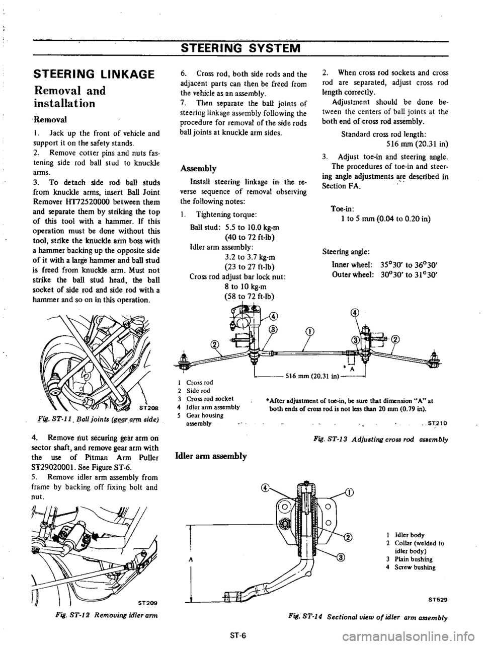
Standard
cross
rod
length
516
rom
20
31
in
3
Adjust
toe
in
and
steering
angle
The
procedures
of
toe
in
and
steer
ing
angle
adjustments
Ie
described
in
Section
F
A
Toe
in
1
to
5
mm
0
04
to
0
20
in
Steering
angle
Inner
wheel
3S030
to
36030
Outer
wheel
30030
to
31030
5t6
mm
20
31
in
1
Cro
s
rod
2
Side
rod
3
Cross
rod
socket
4
Idler
arm
assembly
5
Gear
housing
assembly
Mter
adjustment
of
toe
in
be
sure
that
dimension
A
at
both
ends
of
cross
rod
is
not
less
than
20
nun
0
79
in
Idler
ann
assembly
ST210
Fig
ST
13
Adjusting
cross
rod
assembly
@
1
Idler
body
2
Collar
welded
to
idler
body
A
3
Plain
bushing
4
Screw
bushing
T529
ST
6
Fig
ST
14
Sectional
W
of
idler
arm
as
sembly
Page 412 of 537
I
J
L6
3
4
5
1
Apply
recommended
grease
to
screw
bushing
interior
plain
bushing
interior
dust
seal
inside
and
bushing
sliding
surface
of
idler
ann
Screw
bushing
tightening
torque
12
kg
m
87
ft
lb
2
Before
installing
idler
arm
assem
bly
replace
f
iller
plug
with
grease
nipple
and
apply
recommended
grease
to
idler
ann
through
this
grease
nipple
until
grease
is
forced
out
at
the
lower
end
of
the
dust
seal
lip
Remove
grease
I
8
I
II
I
I
FIODt
Inspection
and
repair
Ball
joint
1
When
ball
stud
is
worn
or
axial
play
is
too
excessive
replace
cross
rod
socket
or
side
rod
with
a
new
one
2
When
dust
cover
is
broken
or
defonned
be
sure
to
replace
with
a
new
one
Axial
end
play
0
1
to
0
5
mm
0
004
to
0
020
in
Initial
swing
torque
S
to
15
kg
cm
70
to
209
in
oz
STEERING
SYSTEM
nipple
and
reinstall
filler
plug
3
In
installing
idler
arm
assembly
make
sure
that
the
standard
dimension
A
is
adjusted
correctly
Standard
dimension
A
137
8
to
139
8
mm
S
42S
to
S
504
in
See
Figure
ST
14
Furthermore
be
sure
to
install
washers
correctly
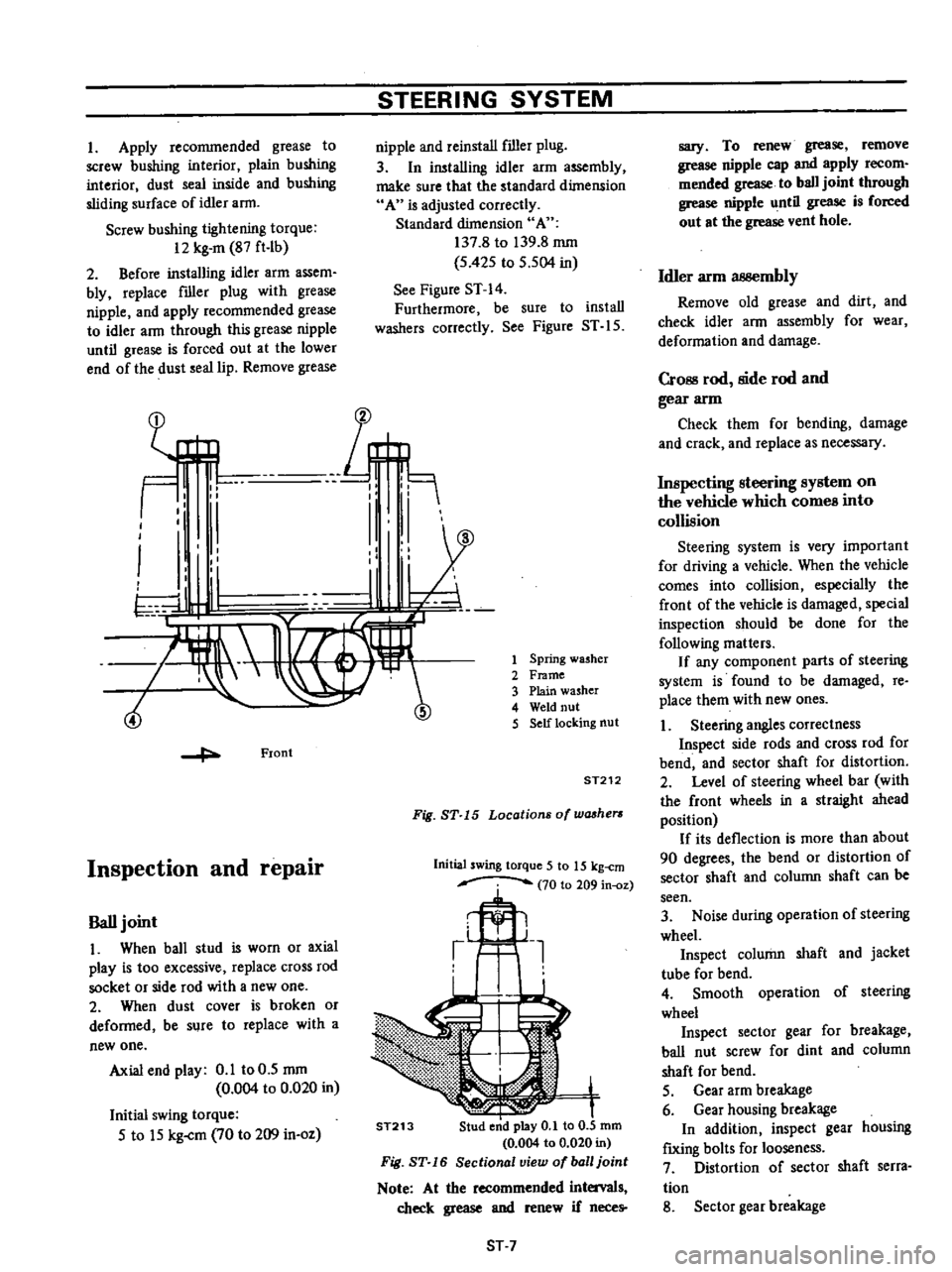
See
Figure
ST
IS
Spring
washer
Frame
Plain
washer
Weld
nut
Self
locking
nut
ST212
Fig
ST
15
Locations
of
washers
Initial
swing
torque
5
to
15
kg
cm
70
to
209
in
oz
ST213
ST
7
sary
To
renew
grease
remove
grease
nipple
cap
and
apply
recom
mended
grease
to
ball
joint
through
grease
nipple
until
grease
is
forced
out
at
the
grease
vent
hole
Idler
arm
3B8embly
Remove
old
grease
and
dirt
and
check
idler
ann
assembly
for
wear
deformation
and
damage
CrOBS
rod
side
rod
and
gear
arm
Check
them
for
bending
damage
and
crack
and
replace
as
necessary
Inspecting
steering
system
on
the
vehicle
which
comes
into
collision
Steering
system
is
very
important
for
driving
a
vehicle
When
the
vehicle
comes
into
collision
especially
the
front
of
the
vehicle
is
damaged
special
inspection
should
be
done
for
the
following
matters
If
any
component
parts
of
steering
system
is
found
to
be
damaged
re
place
them
with
new
ones
1
Steering
angles
correctness
Inspect
side
rods
and
cross
rod
for
bend
and
sector
shaft
for
distortion
2
Level
of
steering
wheel
bar
with
the
front
wheels
in
a
straight
ahead
position
If
its
deflection
is
more
than
about
90
degrees
the
bend
or
distortion
of
sector
shaft
and
column
shaft
can
be
seen
3
Noise
during
operation
of
steering
wheel
Inspect
column
shaft
and
jacket
tube
for
bend
4
Smooth
operation
of
steering
wheel
Inspect
sector
gear
for
breakage
ball
nut
screw
for
dint
and
column
shaft
for
bend
S
Gear
arm
breakage
6
Gear
housing
breakage
In
addition
inspect
gear
housing
f
IXing
bolts
for
looseness
7
Distortion
of
sector
shaft
serra
tion
8
Sector
gear
breakage
Page 413 of 537
STEERING
SYSTEM
9
Column
shaft
breakage
on
the
welded
section
In
addition
inspect
column
shaft
for
scratch
10
Deformation
of
body
construc
tion
and
frame
Inspect
the
installation
portion
of
steering
system
on
the
body
construe
tion
and
frame
for
deformation
or
any
other
faulty
conditions
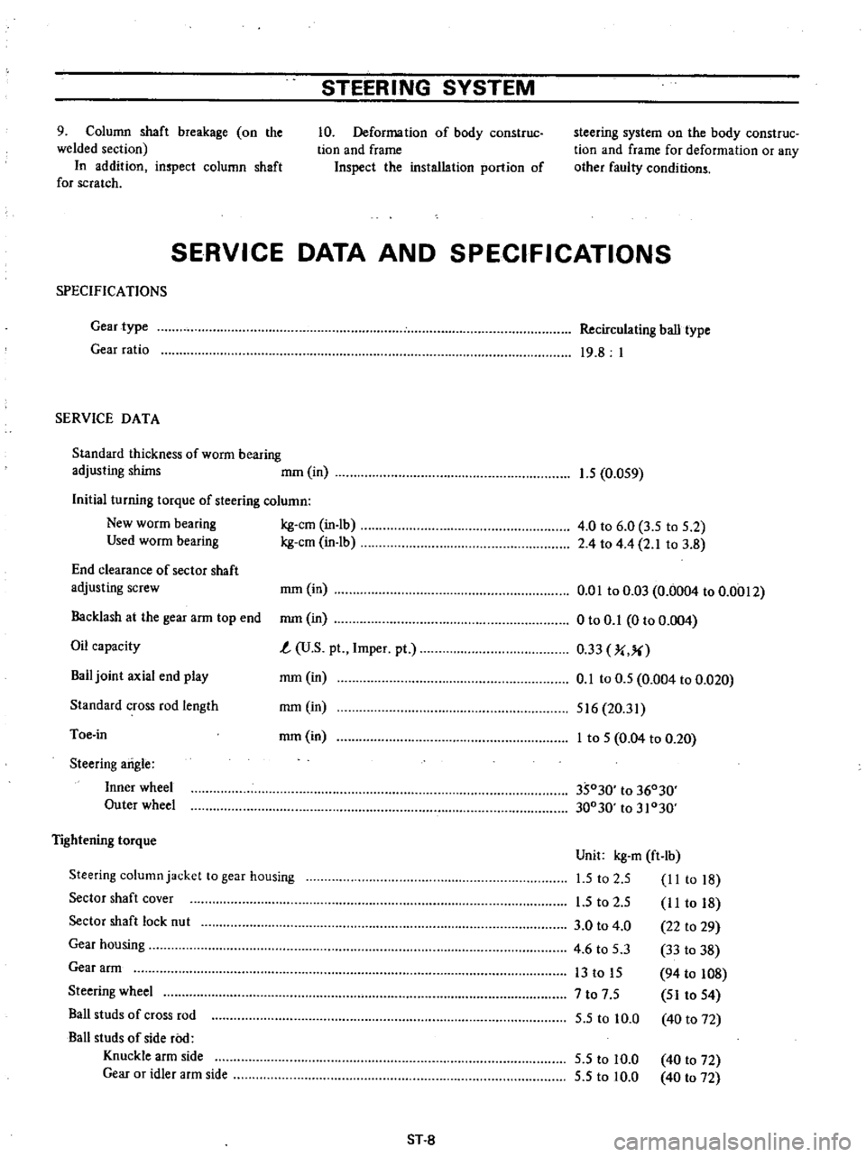
SERVICE
DATA
AND
SPECIFICATIONS
SPECIFICA
nONS
Gear
type
Gear
ratio
SERVICE
DATA
Standard
thickness
of
worm
bearing
adjusting
shims
mOl
in
Initial
turning
torque
of
steering
column
New
worm
bearing
kg
em
in
lb
Used
worm
bearing
kg
em
in
lb
End
clearance
of
sector
shaft
adjusting
screw
rom
in
Backlash
at
the
gear
arm
top
end
rom
in
Oil
capacity
t
U
S
pt
Impel
pt
Bail
joint
axial
end
play
rom
in
Standard
cross
rod
length
rom
in
Toe
in
rom
in
Steering
arigle
Inner
wheel
Outer
wheel
Tightening
torque
Steering
column
jacket
to
gear
housing
Sector
shaft
cover
Sector
shaft
lock
nut
Gear
housing
Gear
arm
Steering
wheel
Bail
studs
of
cross
rod
Ball
studs
of
side
roo
Knuckle
arm
side
Gear
or
idler
arm
side
ST
8
Recirculating
ball
type
19
8
I
1
5
0
OS9
4
0
to
6
0
3
5
to
S
2
2
4
to
4
4
2
1
to
3
8
om
to
0
03
0
0004
to
0
0012
o
to
0
1
0
to
0
004
0
33
J
X
0
1
to
0
5
0
004
to
0
020
516
20
31
I
to
S
0
04
to
0
20
35030
to
36030
30030
to
31030
Unit
kg
m
ft
lb
1
5
to
2
S
II
to
18
I
S
to
2
S
I
I
to
18
3
0
to
4
0
22
to
29
4
6
to
5
3
33
to
38
13
to
IS
94
to
108
7
to
7
S
SI
to
S4
S
S
to
10
0
40
to
72
S
S
to
10
0
S
5
to
10
0
40
to
72
40
to
72
Page 415 of 537
STEERING
SYSTEM
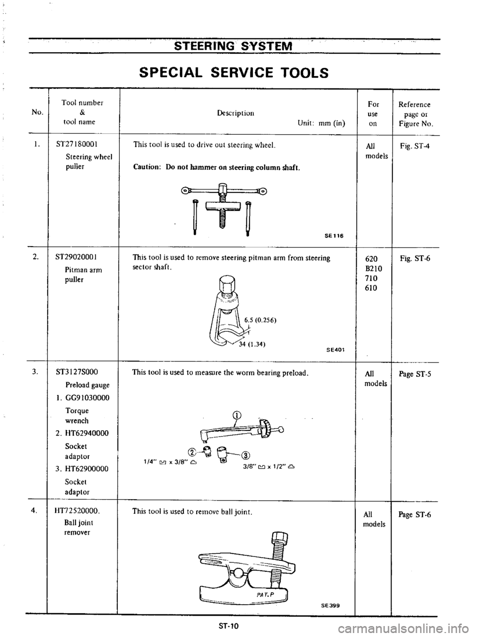
SPECIAL
SERVICE
TOOLS
No
Tool
number
tool
name
Description
Unit
mOl
in
For
use
on
Reference
page
or
Figure
No
ST27I80001
Steering
wheel
puller
This
tool
is
used
to
drive
out
steering
wheel
All
Fig
ST4
models
Caution
Do
not
hammer
on
steering
column
shaft
o
v
J
SE
116
2
ST29020001
Pitman
arm
puller
This
tool
is
used
to
remove
steering
pitman
arm
from
steering
sector
shaft
Fig
ST
6
SE401
3
ST3I
27S000
This
tool
is
used
to
measure
the
worm
bearing
preload
All
Page
ST
5
Preload
gauge
models
GG91030000
Torque
D
wrench
I
2
HT62940000
IJ
Socket
t
Y
ID
adaptor
114
3
8
Go
3
HT62900000
318
1
2
Socket
adaptor
4
HT72520000
This
tool
is
used
to
remove
ball
joint
All
Page
ST
6
Ball
joint
models
remover
620
B210
710
610
SE399
ST
10
Page 523 of 537
Air
Conditioning
1foo
1t
1
t7
LV
I
1
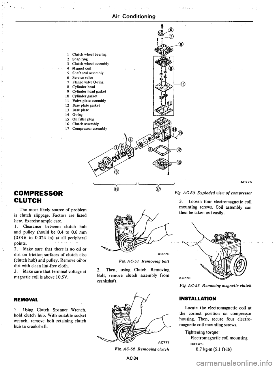
Clutch
wheel
bearing
2
Snap
ring
3
Clutch
wheel
assembly
4
Magnet
coil
5
Shaft
seal
assembly
6
Service
valve
7
Flange
valve
O
ring
8
Cylinder
head
9
Cylinder
head
gasket
10
Cylinder
gasket
11
Valve
plate
assembly
12
Base
plate
gasket
13
Base
plate
14
O
ring
15
Oil
filler
plug
16
Clutch
assembly
17
Compressor
assembly
COMPRESSOR
CLUTCH
The
most
likely
source
of
problem
is
clutch
slippage
Factors
are
listed
here
Exercise
ample
care
I
Clearance
between
clutch
hub
and
pulley
should
be
0
4
to
0
6
mm
0
016
to
0
024
in
at
all
peripheral
points
2
Make
sure
that
there
is
no
oil
or
dirt
on
friction
surfaces
of
clutch
disc
clutch
hub
and
pulley
Remove
oil
or
dirt
with
clean
lint
free
cloth
3
Make
sure
that
terminal
voltage
at
magnetic
coil
is
above
IO
5V
REMOVAL
I
Using
Clutch
Spanner
Wrench
hold
clutch
hub
With
suitable
socket
wrench
remove
bolt
retaining
clutch
hub
to
crankshaft
H
@
@
AC776
Fig
AC
51
Remouing
bolt
2
Then
using
Clutch
Removing
Bolt
remove
clutch
assembly
from
cmnkshaft
Fig
AC
52
Removing
clutch
AC34
AC775
Fig
A
C
50
Exploded
view
of
compressor
3
Loosen
four
electromagnetic
coil
mounting
screws
Coil
assembly
can
then
be
taken
out
easily
Fig
A
C
53
Removing
magnetic
clutch
INSTALLATION
Locate
the
electromagnetic
coil
at
the
correct
position
on
compressor
housing
Then
secure
four
electro
magnetic
coil
mounting
screws
Tightening
torque
Electromagnetic
coil
mounting
screws
0
7
kg
m
5
1
ft
Ib