ALIGNMENT DATSUN PICK-UP 1977 Service Manual
[x] Cancel search | Manufacturer: DATSUN, Model Year: 1977, Model line: PICK-UP, Model: DATSUN PICK-UP 1977Pages: 537, PDF Size: 35.48 MB
Page 52 of 537

EM103
EM411
Fig
EM
29
Remouingpi
tonpin
Fig
EM
26
Remouing
rear
oil
eal
41
Remove
crankshaft
42
Remove
baffie
plate
and
cyl
inder
block
net
Fig
EM
27
Removing
baffle
plate
and
nel
PISTONS
AND
CONNECTING
RODS
Remove
piston
rings
with
a
ring
remover
O
EM102
Fig
EM
28
Removing
pilton
rings
2
Press
piston
pin
out
with
Piston
Pin
Press
Stand
STl3030001
Engine
Mechanical
3
Keep
disassembled
parts
in
order
CYLINDER
HEAD
I
Remove
valve
rocker
springs
Loosen
valve
rocker
pivot
lock
nut
and
remove
rocker
arm
by
pressing
valve
spring
down
Fig
EM
3D
Removing
rockerarrm
2
Remove
locate
plate
and
remove
camshaft
EM105
Fig
EM
31
Remouing
cammaft
EM
7
Note
Be
careful
not
to
damage
eam
shaft
bearings
and
earn
lobes
3
Remove
valves
using
Valve
Lifter
STl2070000
STl2070000
Fig
EM
32
Removing
ualves
Notes
a
Take
care
not
to
lose
valve
spring
seat
oil
seal
valve
collet
and
valve
rocker
guide
b
Be
sure
to
keep
camshaft
bearings
intact
or
the
bearing
center
is
liable
to
come
out
of
alignment
61
8
Exhaust
Intake
EM101
Fig
EM
33
Value
components
Page 53 of 537
r
Engine
Mechanical
INSPECTION
AND
REPAIR
PREPARATION
FOR
INSPECTION
CYLINDER
HEAD
AND
VALVE
CHECKING
CYLINDER
HEAD
MATING
FACE
VALVE
ASSEMBLY
VALVE
SPRING
ROCKER
ARM
AND
VALVE
ROCKER
PIVOT
VALVE
GUIDE
VALVE
SEAT
INSERTS
CAMSHAFT
AND
CAMSHAFT
BEARING
CAMSHAFT
BEARING
CLEARANCE
VALVE
TIMING
CAMSHAFT
ALIGNMENT
CYLINDER
BLOCK
HOW
TO
MEASURE
CYLINDER
BORE
CYLINDER
BORING
PREPARATION
FOR
INSPECTI
N
I
Before
cleaning
check
for
signs
of
water
and
oil
leaks
in
cylinder
block
and
head
2
Clean
oil
carbon
deposits
and
sealant
from
an
parts
Remove
gasket
3
Clean
all
oil
holes
with
solvent
and
dry
with
compressed
air
Make
sure
that
they
are
not
restricted
CYLINDER
HEAD
AND
VALVE
CHECKING
CYLINDER
HEAD
MATING
FACE
EM407
Fig
EM
34
Cylinder
head
CONTENTS
EM
8
EM
B
EM
8
EM
8
EM
9
EM
lO
EM
l0
EM
11
EM
12
EM
12
EM
12
EM
13
EM
13
EM
13
EM
14
PISTONS
PISTON
PINS
AND
PISTON
RINGS
CONNECTING
ROD
CRANKSHAFT
BUSHING
AND
BEARING
MEASUREMENT
OF
MAIN
BEARING
CLEARANCE
MEASUREMENT
OF
CONNECTING
ROD
BEARING
CLEARANCE
FITTING
BEARINGS
MISCELLANEOUS
COMPONENTS
CRANKSHAFT
AND
CAMSHAFT
SPROCKETS
CHAIN
TENSIONER
AND
CHAIN
GUIDE
FLYWHEEL
FRONT
COVER
AND
REAR
OIL
SEAL
Note
Never
remove
camshaft
bear
ings
unless
you
have
a
Suitable
machine
or
boring
Camshaft
bear
ing
in
line
If
you
once
remove
camshaft
bearings
bearing
centers
will
come
out
o
alignment
reo
conditioning
is
very
difficult
with
out
center
borings
L
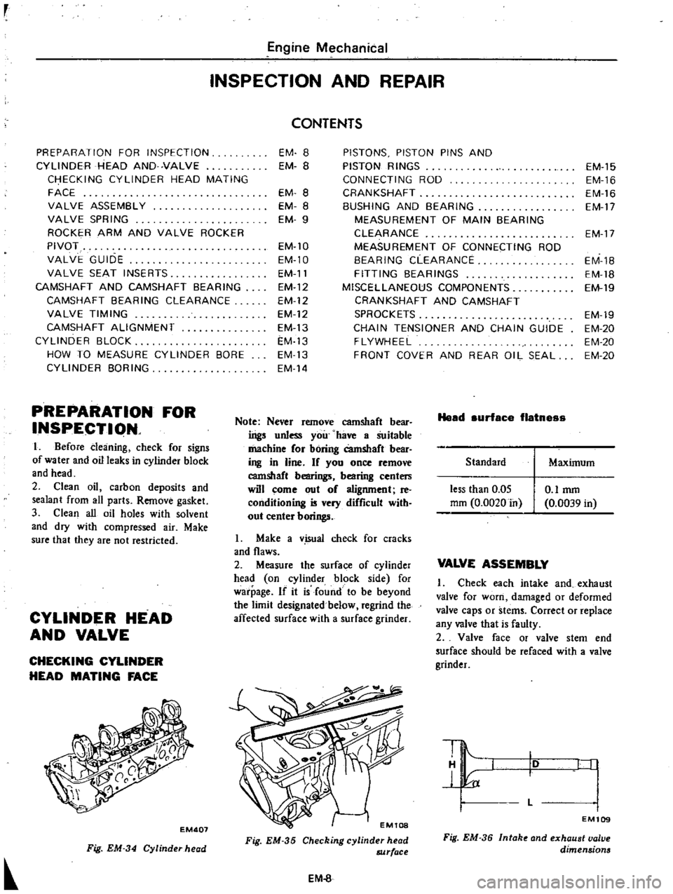
Make
a
v
isual
check
for
cracks
and
flaws
2
Measure
the
surface
of
cylinder
head
on
cylinder
block
side
for
warpage
If
it
is
found
to
be
beyond
the
limit
designated
below
regrind
the
affected
surface
with
a
surface
grinder
Fig
EM
35
Checking
cylinder
head
8JJrface
EM
8
Head
surface
flatnes
Standard
less
than
0
05
mm
0
0020
in
O
lmm
0
0039
in
EM
15
EM
16
EM
16
EM
17
EM
17
EM
1B
EM
18
EM
19
EM
19
EM
20
EM
20
EM
20
Maximum
VALVE
ASSEMBLY
Check
each
intake
and
exhaust
valve
for
worn
damaged
or
deformed
valve
caps
or
stems
Correct
or
replace
any
valve
that
is
faulty
2
Valve
face
or
valve
stem
end
surface
should
be
refaced
with
a
valve
grinder
10
L
I
I
I
EM109
Fig
EM
36
Intak
and
exhaust
valve
dimensions
Page 58 of 537
Standard
Camshaft
bend
mm
in
0
02
0
0008
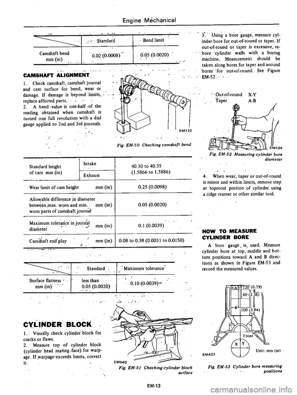
CAMSHAFT
ALIGNMENT
I
Check
camshaft
camshaft
journal
and
earn
surface
for
bend
wear
or
damage
If
damage
is
beyond
limits
replace
affected
parts
2
A
bend
value
is
one
half
of
the
reading
obtained
when
camshaft
is
turned
one
full
revolution
with
a
dial
gauge
applied
to
2nd
and
3rd
journals
Standard
height
of
tam
mm
in
I
Intake
1
Exhaust
Wear
limit
of
earn
height
mm
in
Allo
able
difference
in
diam
ter
betweim
max
worn
and
min
mm
in
worn
parts
of
c
mshaft
journal
Engine
Mechanical
Bend
limit
0
05
0
0020
I
Fig
EM
50
Checking
camMa
t
bend
40
30
to
40
35
1
5866
to
1
5886
0
25
0
0098
0
05
0
0020
Maximum
tolerance
in
j01
irri
mm
in
0
1
0
0039
diameter
CamShaft
end
play
mm
in
0
08
to
0
38
0
0031
to
0
0150
Standard
Surface
flatness
mm
in
less
than
0
05
0
0020
Cy
LlNDER
BLOCK
I
Visually
check
cylinder
block
for
cracks
or
flaws
2
Measure
top
of
cylinder
block
cylinder
head
mating
face
for
warp
age
If
warpage
exceeds
limits
correct
it
Maximum
tolerance
0
10
0
0039
EM540
Fig
EM
51
Cheching
cylinder
block
au
rface
EM
13
j
Using
a
bore
gauge
measure
cyl
inder
bore
for
out
of
round
or
taper
If
out
of
round
or
taper
is
excessive
re
bore
cylinder
walls
with
a
boring
machine
Measuremen
t
should
be
taken
along
bores
for
taper
and
around
bores
for
out
of
round
See
Figure
EM
52
Qu
t
of
round
Taper
X
Y
A
B
M12
Fig
EM
52
Measuring
cylinder
bore
diameter
4
When
wear
taper
or
out
of
round
is
minor
and
within
limits
remove
step
at
topmost
portion
of
cylinder
using
a
ridge
reamer
or
other
similar
tool
HOW
TO
MEASURE
CYLINDER
BORE
A
bore
gauge
is
used
Measure
cylind
r
bore
at
top
middle
and
bot
tom
positions
toward
A
and
B
direc
tions
as
shown
in
Figure
EM
53
and
record
the
measured
values
A
I
120
0
79
IlL
60
2
36
lll
B
100
3
94
el
1
Unit
mm
m
EM
22
r
Fig
EM
53
Cylinder
bort
me08Uring
positions
Page 61 of 537
r
Piston
pin
outside
diameter
Piston
pin
hole
diameter
Piston
pin
to
piston
clearance
I
Interference
fit
of
piston
pin
to
connecting
rod
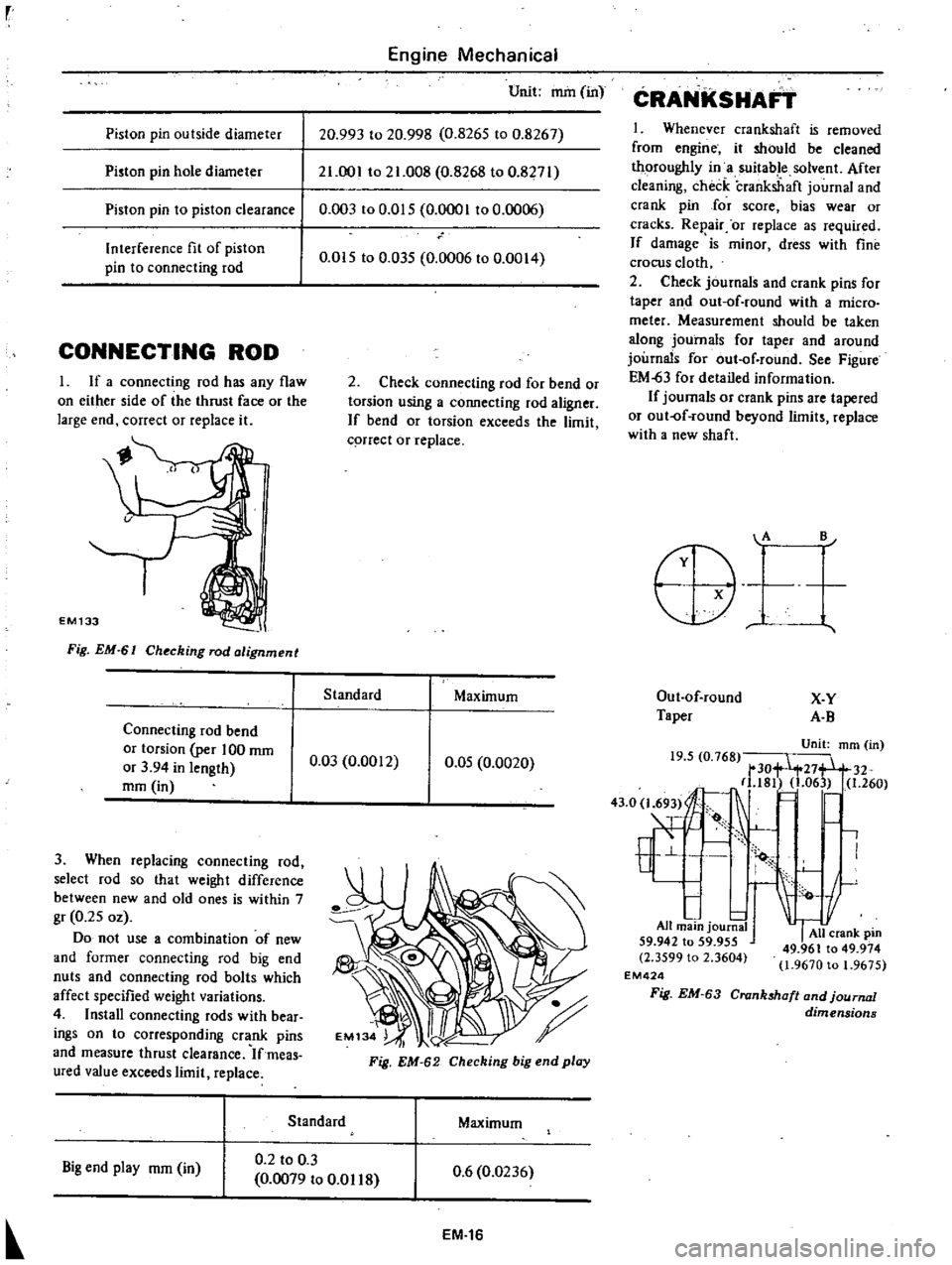
CONNECTING
ROD
I
If
a
connecting
rod
has
any
flaw
on
either
side
of
the
thrust
face
or
the
large
end
correct
or
replace
it
EM133
Fig
EM
61
Ch
cking
rod
alignment
Connecting
rod
bend
or
torsion
per
100
mm
or
3
94
in
length
mm
in
3
When
replacing
connecting
rod
select
rod
so
that
weight
difference
between
new
and
old
ones
is
within
7
gr
0
25
oz
Do
not
use
a
combination
of
new
and
former
connecting
rod
big
end
nuts
and
connecting
rod
bolts
which
affect
specified
weight
variations
4
Install
connecting
rods
with
bear
ings
on
to
corresponding
crank
pins
and
measure
thrust
clearance
Ifmeas
ured
value
exceeds
limit
replace
Engine
Mechanical
Unit
mm
in
20
993
to
20
998
0
8265
to
0
8267
21
001
to
21
008
0
8268
to
0
8271
0
003
to
0
015
0
0001
to
0
006
0
015
to
0
035
0
0006
to
0
0014
2
Check
connecting
rod
for
bend
or
torsion
using
a
connecting
rod
aligner
If
bend
or
torsion
exceeds
the
limit
q
rrect
or
replace
Standard
Maximum
0
03
0
0012
0
05
0
0020
Fig
EM
62
Checking
big
end
play
Standard
Maximum
Big
end
play
mm
in
0
2
to
0
3
0
0079
to
0
01
18
0
6
0
0236
EM
16
CRANKSHAFT
1
Whenever
crankshaft
is
removed
from
engine
it
should
be
cleaned
thoroughly
in
a
suitable
solvent
After
cleaning
check
crankshaft
journal
and
crank
pin
Jor
score
bias
wear
or
cracks
Rep
air
or
replace
as
required
If
damage
is
minor
dress
with
fine
crocus
cloth
2
Check
journals
and
crank
pins
for
taper
and
out
of
round
with
a
micro
meter
Measurement
should
be
taken
along
journals
for
taper
and
around
journals
for
out
of
round
See
Figure
EM
63
for
detailed
information
If
journals
or
crank
pins
are
tapered
or
out
of
round
beyond
limits
replace
with
a
new
shaft
A
B
Out
of
round
X
Y
Taper
A
B
Unit
mm
in
19
5
0
768
tt
30
27
32
181
1
06
1
260
43
O
l
69
I
E
1
All
main
journa
59
942
to
59
955
All
crank
pm
2
3599
l
2
3604
49
961
to
49
974
o
1
9670
to
1
9675
EM424
Fig
EM
63
Crankshaft
and
journal
dimensions
Page 76 of 537
Engine
Mechanical
TROUBLE
DIAGNOSES
AND
CORRECTIONS
Condition
I
Noisy
engine
Knocking
of
crankshaft
and
bearing
Knocking
of
piston
and
connecting
rod
Camshaft
knocking
Timing
chain
noise
Camshaft
and
valve
mechanism
knocking
Water
pump
knocking
Probable
cause
Loose
main
bearing
Seized
bearing
Bent
crankshaft
Uneven
wear
of
journal
Excessive
crankshaft
end
play
Loose
bearing
Seized
bearing
Loose
piston
pin
Loose
piston
in
cylinder
Broken
piston
ring
Improper
connecting
rod
alignment
Loose
bearing
Excessive
axial
play
Rough
gear
teeth
Broken
eam
gear
Improper
chain
tension
Worn
and
or
damaged
chain
Worn
sprocket
Worn
and
or
broken
tension
adjusting
mechanism
Excessive
camshaft
and
bearing
clearance
Improper
valve
clearance
Worn
adjusting
screw
Worn
rocker
face
Loose
valve
stem
i1
1
guide
Weakened
valve
spring
Seized
valve
Improper
shaft
end
play
Broken
impeller
II
Other
mechanical
troubles
Stuck
valve
Improper
valve
clearance
Insufficient
clearance
between
valve
stem
and
guide
Weakened
or
broken
valve
spring
Biting
or
damage
of
valve
stem
Poor
Quality
of
fuel
EM
31
Corrective
action
Replace
Replace
Repair
or
replace
Correct
Replace
cen
ter
bearing
Replace
Replace
Replace
pin
or
bushing
Recondition
cylinder
Replace
Realign
Replace
Replace
bearing
thrust
plate
Repair
Replace
Adjust
Replace
Replace
Replace
Replace
Adjust
Replace
Replace
Replace
guide
Replace
Repair
or
replace
Replace
Replace
Adjust
Clean
stem
or
ream
guide
Replace
Replace
or
clean
Use
ood
fuel
Page 77 of 537

Condition
Seized
valve
seat
Excessively
worn
cylinder
and
piston
Faulty
connecting
rod
Faulty
crankshaft
bearing
Engine
Mechanical
Probable
cause
Improper
valve
clearance
Weakened
valve
spring
Thin
valve
head
edge
Narrow
valve
seat
Overheating
Over
speeding
Stuck
valve
guide
Shortage
of
engine
oil
Dirty
engine
oil
Poor
quality
of
oiL
Overheating
Wrong
assembly
of
piston
with
connecting
rod
Improper
piston
ring
clearance
Broken
piston
ring
Dirty
aii
cleaner
Mixture
too
rich
Engine
over
run
Stuck
choke
valve
Overchoking
Shortage
of
engine
oil
Low
oil
pressure
Poor
quality
of
engine
oil
Rough
surface
of
craokshaft
Clogged
oil
passage
Bearing
worn
or
eccentric
Bearingimproperly
assembled
Loose
bearing
Connecting
rod
alignment
incorrect
Shortage
of
engine
oil
Low
oil
pressure
Poor
quality
of
engine
oil
Craokshaft
journal
worn
or
out
of
round
Clogged
oil
passage
in
crankshaft
Bearing
worn
or
eccentric
Bearing
improperly
assembled
Eccentric
craokshaft
or
bearing
EM
32
Corrective
action
Adjust
Replace
Replace
valve
Reface
Repair
or
replace
Drive
at
proper
speeds
Repair
Add
or
replace
oil
Clean
crankcase
replace
oil
and
oil
niter
element
Use
right
oil
Repair
or
replace
Repair
or
replace
Adjust
Replace
Clean
Adjust
Drive
at
proper
speeds
Clean
and
adjust
Start
correct
way
Add
oiL
Correct
Use
proper
oil
Grind
and
replace
bearing
Clean
Replace
Correct
Replace
Repair
or
replace
Add
or
replace
Correct
Use
proper
oil
Repair
Clean
Replace
Correct
Replace
Page 313 of 537
In
these
cases
the
transmission
must
be
repaired
Notes
a
In
checking
oil
level
use
special
paper
cloth
to
handle
the
level
gauge
and
be
careful
not
to
let
the
scraps
of
paper
and
cloth
stick
to
the
gauge
b
Insert
the
gauge
fully
and
take
it
out
quickly
before
splashing
oil
adheres
to
the
gauge
Then
observe
the
level
c
Use
automatic
transmission
fluid
having
DEXRON
identifications
only
in
the
3N71B
automatic
trans
mission
d
Pay
attention
because
the
oil
to
be
used
differs
from
that
used
in
the
Nissan
Full
Automatic
TranSJTIis
sion
3N71A
Never
mix
the
oils
INSPECTION
AND
REPAIR
OF
OIL
LEAKAGE
When
oil
leakage
takes
place
the
portion
near
the
leakage
is
covered
with
oil
presenting
difficulty
in
detecting
the
spot
Therefore
the
places
where
oil
seals
and
gaskets
are
equipped
are
enumerated
below
11
Converter
housing
Rubber
ring
of
oil
pump
housing
Oil
seal
of
oil
pump
housing
Oil
seal
of
engine
crankshaft
Bolts
of
converter
housing
to
case
2
Trarismission
and
rear
extension
Junction
of
transm
ss
ion
and
rear
extension
J
Oil
cooler
tube
connectors
Oil
pan
Oil
pressure
inspection
holes
Refer
to
Figure
AT
il2
Mounting
portion
of
vacuum
dia
phragm
and
downshift
solenoid
Breather
and
oil
charging
pipe
Speedometer
pinion
sleeve
Oil
se
l
of
rear
extension
To
exactly
locate
the
place
of
oil
leaka
le
proceed
as
follows
Place
the
vehicle
in
a
pit
and
by
sampling
the
leaked
oil
determine
if
it
is
the
torque
converter
oil
The
torque
converter
oil
has
a
color
like
r
d
wine
So
it
is
easily
distinguished
from
engine
oil
or
gear
oil
Automatic
rransmission
Wipe
off
the
leaking
oil
and
dust
and
deiecl
the
spol
of
oil
eakage
l
se
nonflammable
organic
solve
t
s
ch
as
carbon
tetrachloride
for
wiping
Raise
the
oil
tcmperalure
by
op
erating
the
engine
and
shift
the
lever
to
D
to
increase
the
oil
pressure
The
spot
of
oil
lcakage
will
then
be
found
more
easily
Note
As
oil
leakage
from
the
breaih
er
does
not
take
place
except
when
running
at
high
speed
it
is
impos
sible
to
locate
this
leakage
with
vehicle
stationary
CHECKING
ENGINE
IDLING
REVOLUTION
The
engine
idling
revolution
should
be
properly
adjusted
If
the
engine
revolution
is
too
low
the
engine
does
not
operate
smoothly
and
if
too
high
a
strong
shock
or
creep
develops
when
changing
over
from
N
to
D
or
R
CHECKING
AND
ADJUSTING
KICK
DOWN
SWITCH
AND
DOWNSHIFT
SOLENOID
When
the
kickdown
operation
is
not
made
properly
or
the
speed
chang
ing
point
s
too
high
check
the
kick
down
switch
downshift
solenoid
and
wiring
between
them
When
the
igni
li
n
key
is
pqsitioned
a
t
the
I
st
stage
nd
the
accelerator
pedal
is
depressed
deeply
the
switch
contact
should
be
closed
and
the
solenoid
should
click
If
it
does
not
click
it
indicates
a
defect
Then
check
each
part
with
the
testing
instruments
See
Figure
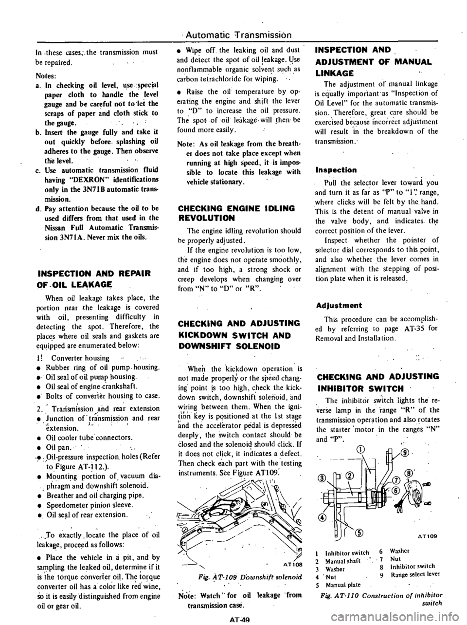
ATl09
d
I
t
AT10S
Fig
AT
109
Downshift
solenoid
Note
Watch
for
oil
leakage
from
transmission
case
AT
4Q
INSPECTION
AND
ADJUSTMENT
OF
MANUAL
LINKAGE
The
adjustmcnt
of
manual
linkage
is
equaUy
important
as
Inspection
of
Oil
Level
for
the
automatic
transmis
sion
Thereforc
great
care
should
be
exercised
because
incorrect
adjustment
will
rcsult
in
the
brcakdown
of
the
transmission
Inspection
Pull
the
selector
lever
toward
you
and
turn
it
as
far
as
P
to
I
range
wherc
clicks
will
be
felt
by
the
hand
This
is
the
detcnt
of
manual
valve
in
the
valve
body
and
indicates
th
correct
position
of
the
lever
Inspect
whether
the
pointer
of
selector
dial
corresponds
to
this
point
and
also
whether
the
lever
comes
in
alignment
with
the
stepping
of
posi
tion
plate
when
it
is
released
Adjustment
This
procedure
can
be
accomplish
ed
by
refcrring
to
page
AT
35
for
Removal
and
Installa
tion
CHECKING
AND
ADJUSTING
INHIBITOR
SWITCH
The
inhibitor
switch
lights
the
re
verse
lamp
in
the
range
R
of
the
transmission
operatio
l
and
also
rotates
the
starter
motor
in
the
ranges
N
and
P
CD
@
b
ell
If
L
t
7
4l
@
1l
j7
@
@
@
dl
AT109
6
Washer
7
Nut
8
Inhibitor
switch
9
Range
select
lever
t
Inhibitor
switch
2
Manual
shaft
3
Washer
4
Nut
5
Manual
plate
Fig
AT
110
Construction
of
inhibitor
switch
Page 314 of 537
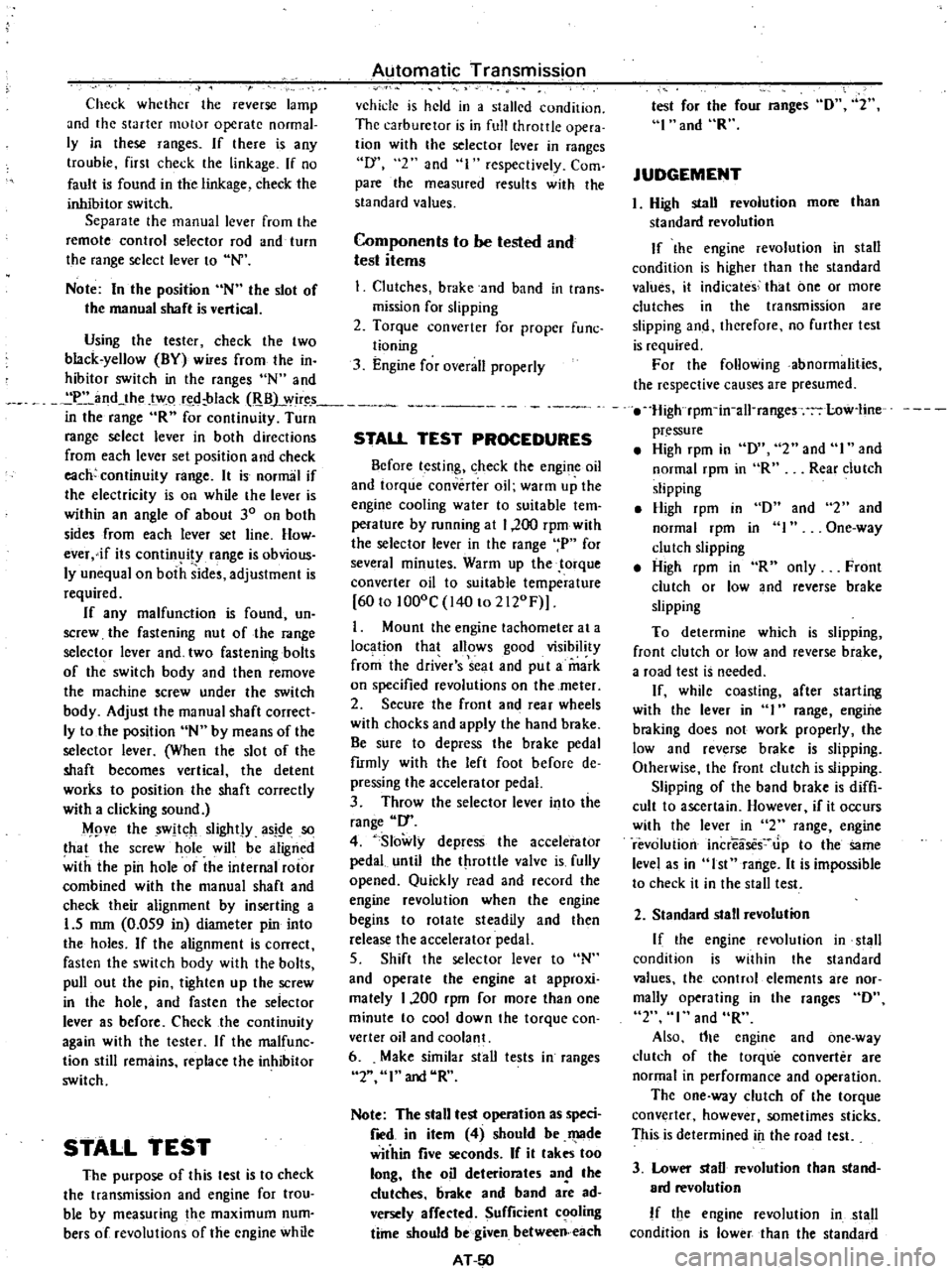
Using
the
tester
check
the
two
black
yellow
BY
wires
from
the
in
hibitor
switch
in
the
ranges
N
and
I
and
the
tw
re
d
black
RBj
wir
s
in
the
range
R
for
continuity
Turn
range
select
lever
in
both
directions
from
each
lever
set
position
and
check
each
continuity
range
It
is
normal
if
the
electricity
is
on
while
the
lever
is
within
an
angle
of
about
30
on
both
sides
from
each
lever
set
line
How
ever
if
its
continl
ity
range
is
obvious
ly
unequal
on
both
sides
adjustment
is
required
If
any
malfunction
is
found
un
screw
the
fastening
nut
of
the
range
selector
lever
and
two
fastening
bolts
of
the
switch
body
and
then
remove
the
machine
screw
under
the
switch
body
Adjust
the
manual
shaft
correct
ly
to
the
position
N
by
means
of
the
selector
lever
When
the
slot
of
the
shaft
becomes
vertical
the
detent
works
to
position
the
shaft
correctly
with
a
clicking
sound
MSlVe
the
switch
slightly
asj
Je
so
that
the
screw
hole
will
be
aligned
with
the
pin
hole
of
the
internal
rotor
combined
with
the
manual
shaft
and
check
their
alignment
by
inserting
a
1
5
mm
0
059
in
diameter
pin
into
the
holes
If
the
alignment
is
correct
fasten
the
switch
body
with
the
bolts
pull
out
the
pin
tighten
up
the
screw
in
the
hole
and
fasten
the
selector
lever
as
before
Check
the
continuity
again
with
the
tester
If
the
malfunc
tion
still
remains
replace
the
inhibitor
switch
Chcck
whether
the
reverse
lamp
and
the
starter
motor
operate
normal
ly
in
these
ranges
If
Ihere
is
any
lrouble
first
check
the
linkage
If
no
fault
is
found
in
the
linkage
check
the
inhibitor
switch
Separate
the
manual
lever
from
Ihe
remote
control
selector
rod
and
turn
the
range
selcct
lever
to
N
Note
In
the
position
N
the
slot
of
the
manual
shaft
is
vertical
STALL
TEST
The
purpose
of
this
test
is
to
check
the
transmission
and
engine
for
trou
ble
by
measuring
the
maximum
num
bers
of
revolutions
of
the
engine
while
Automatic
Transmission
vehicle
is
held
in
a
stalled
condition
The
carburctor
is
in
full
throttle
opera
tion
with
the
selector
lever
in
ranges
f
2
and
I
respectively
Com
pare
the
measured
results
with
the
slandard
values
Components
to
be
tested
and
test
items
I
Clutches
brake
and
band
in
trans
mission
for
slipping
2
Torque
converter
for
proper
fune
tioning
3
Engine
for
overall
properly
STALL
TEST
PROCEDURES
Before
Icsting
c
heck
the
engine
oil
and
torque
converter
oil
warm
up
the
engine
cooling
water
to
suitable
tem
perature
by
running
at
1
200
rpm
with
the
selector
lever
in
the
range
P
for
several
minutes
Warm
up
the
torque
converter
oil
to
suitable
temperature
6010
1000C
140
to
2l20F
I
Mount
the
engine
tachometer
at
a
location
that
allows
good
visibility
fro
the
dri
er
s
seat
and
put
a
mark
on
specified
revolutions
on
the
meter
2
Secure
the
front
and
rear
wheels
with
chocks
and
apply
the
hand
brake
Be
sure
to
depress
the
brake
pedal
fumly
with
the
left
foot
before
de
pressing
the
accelerator
pedal
3
Throw
the
selector
lever
into
the
range
1
4
Slowly
depress
the
accelerator
pedal
until
the
throttle
valvc
is
fully
opened
Quickly
read
and
record
the
engine
revolution
when
the
engine
begins
to
rotate
steadily
and
then
release
the
accelerator
pedal
5
Shift
the
selector
lever
to
N
and
operate
the
engine
at
approxi
mately
1
200
rpm
for
more
than
one
minute
to
cool
down
the
torque
con
ver
ter
oil
and
coolant
6
Make
similar
stall
tests
in
ranges
2
I
and
RIO
Note
The
stall
test
operation
as
speci
f
d
in
item
4
should
be
I
l3de
wiihin
five
seconds
If
it
takes
too
long
the
oil
deteriorates
an
the
clutches
brake
and
band
are
ad
versely
affected
Sufficient
cooling
time
should
be
given
between
each
AT
5O
test
for
the
four
ranges
0
2
I
and
R
JUDGEMENT
High
stall
revolution
more
than
standard
revolution
If
the
engine
revolution
in
stall
condition
is
higher
than
the
standard
values
it
indicates
that
one
or
more
clutches
in
the
transmission
are
slipping
and
therefore
no
further
test
is
required
For
the
following
abnormalities
the
respective
causes
are
presumed
High
rpm
in
all
ranges
low
Iine
pressure
High
rpm
in
D
2
and
I
and
normal
rpm
in
R
Rear
clutch
slipping
High
rpm
in
0
and
normal
rpm
in
I
clutch
slipping
High
rpm
in
R
only
Front
clutch
or
low
and
reverse
brake
slipping
To
determine
which
is
slipping
front
clutch
or
low
and
reverse
brake
a
road
test
is
nceded
If
whilc
coasting
after
starting
with
the
lever
in
1
range
engine
braking
does
not
work
properly
the
low
and
reverse
brake
is
slipping
Otherwise
the
front
clutch
is
slipping
Slipping
of
the
band
brake
is
diffi
cult
to
ascertain
However
if
it
occurs
with
the
lever
in
2
range
engine
revolution
increases
Jp
to
thesarne
level
as
in
I
strange
It
is
impossible
to
check
it
in
the
stall
test
2
and
One
way
2
Standard
stall
revolution
If
the
engine
revolution
in
stall
condition
is
within
the
standard
values
the
control
elements
are
nor
mally
operating
in
the
ranges
0
2
I
and
R
Also
tIle
engine
and
one
way
clutch
of
the
torque
converter
are
normal
in
performance
and
operation
The
one
way
clutch
of
the
torque
converter
however
sometimes
sticks
This
is
determined
in
the
road
test
3
Lower
stall
revolution
than
stand
ard
revolution
If
the
engine
revolution
in
stall
condition
is
lower
than
the
standard
Page 351 of 537
Front
Axle
Front
Suspension
FRONT
AXLE
AND
FRONT
SUSPENSION
CONTENTS
GENERAL
DESCRIPTION
FRONT
AXLE
REMOVAL
AND
INSTALLATION
WHEEL
BEARING
ADJUSTMENT
DISASSEMBLY
AND
ASSEMBLY
INSPECTION
SHOCK
ABSORBER
REMOVAL
AND
INSTALLATION
INSPECTION
STABILIZER
REMOVAL
AND
INSTALLATION
INSPECTION
TENSION
ROD
FA
2
FA
3
FA
3
FA
4
FA
4
FA
5
FA
8
FA
8
FA
8
FA
8
FA
8
FA
8
FA
8
REMOVAL
AND
INSTALLATION
INSPECTION
TORSION
BAR
SPRING
REMOVAL
AND
INSTALLATION
INSPECTION
UPPER
AND
LOWER
LINKS
FjEMOVAL
AND
INSTALLATION
DISASSEMBLY
AND
ASSEMBLY
INSPECTION
ADJUSTMENT
VEHICLE
POSTURE
WHEEL
ALIGNMENT
STEERING
ANGLE
GENERAL
DESCRIPTION
uUl
FA
8
FA
9
FA
9
FA
9
FA
9
FA
10
FA
l0
FA
ll
FA
ll
FA
Il
FA
ll
FA
12
FA
12
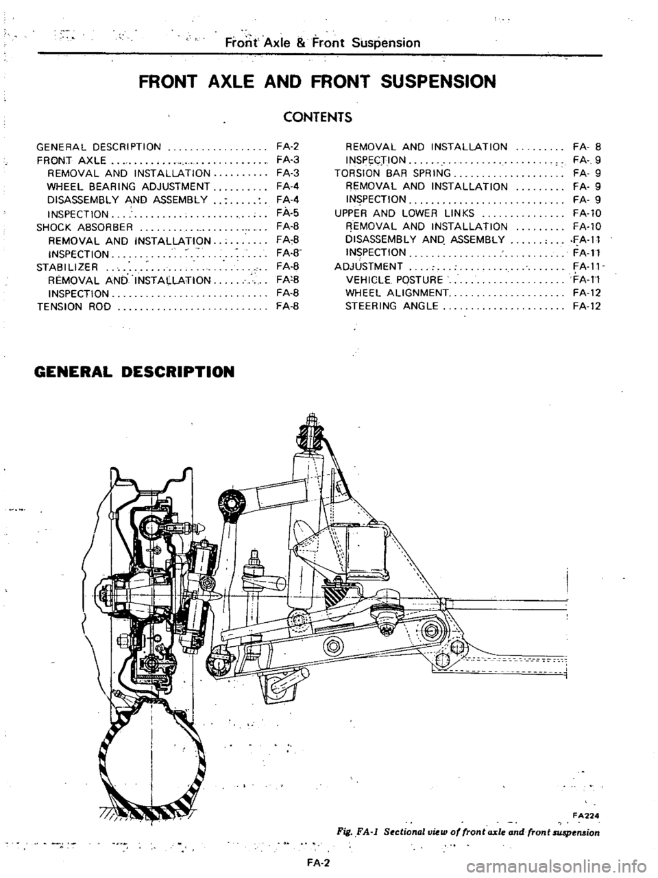
FA224
Fig
FA
j
SectionallJiew
of
fronta
xle
and
fron
t
suspension
FA
2
Page 361 of 537
WHEEL
ALIGNMENT
Correct
front
wheel
alignment
attains
proper
vehicle
handling
charac
teristics
and
the
least
steering
effort
with
a
minimum
amount
of
tire
wear
Before
adjusting
front
wheel
align
ment
make
sure
to
carry
out
a
pre
liminary
inspection
of
the
front
end
parts
for
the
following
conditions
1
Tire
pressure
and
balance
2
Wheel
bearings
and
nuts
3
Steering
gear
play
4
Steering
gear
housing
at
frame
S
Steering
linkage
and
connections
6
Shock
absorber
action
When
using
the
equipment
for
front
wheel
alignment
inspection
follow
the
inst
c
tions
furnished
with
the
equip
ment
Furthennore
the
inspection
should
be
made
with
the
vehicle
level
and
at
curb
weight
Camber
and
caster
Measure
camber
and
caster
and
adjust
them
in
accordance
with
the
following
procedures
if
necessary
Both
camber
and
caster
are
ad
justed
by
increasing
and
decreasing
thickness
of
adjust
shim
inserted
be
tween
upper
link
spindle
and
upper
link
mounting
bracket
To
adjust
caster
make
a
difference
between
thickness
of
front
and
rear
shims
By
adding
a
shim
I
mm
0
039
in
at
front
side
caster
will
be
de
creased
by
33
At
the
same
time
camber
will
also
be
decreased
by
6
S
To
adjust
camber
add
or
remove
an
equal
amount
of
shims
to
front
and
rear
sides
By
adding
a
pack
of
shims
I
mOl
0
039
in
thick
at
both
sides
camber
will
be
decreased
by
13
Shims
are
available
in
I
mm
0
039
in
2
mOl
0
079
in
and
4
mOl
0
157
in
thickness
Front
Axle
Front
Suspension
FA243
Fig
FA
25
Adjustingcamberand
cCJ
ter
Notes
a
Do
not
make
difference
between
front
and
rear
shims
in
thickness
beyond
2
mm
0
079
in
on
a
upper
link
spindle
b
Umit
shim
thickness
for
anyone
stack
within
6
nun
0
236
in
c
Do
not
use
shims
for
anyone
stack
more
the
2
sheets
Toe
in
Measure
toe
in
and
adjust
if
neces
sary
For
adjustment
carry
out
the
follOWIng
procedures
Turn
steering
wheel
to
straight
ahead
position
with
front
wheels
in
the
same
position
Then
check
steer
ing
gear
straight
ahead
position
Loosen
lock
nuts
@
left
hand
thread
and
ID
right
hand
thread
and
turn
cross
rod
CD
to
adjust
toe
in
Turn
cross
rod
to
forward
direction
as
shown
by
arrow
and
toe
in
is
reduced
When
cross
rod
is
turned
to
opposite
side
toe
in
is
increased
After
correct
toe
in
is
obtained
tighten
lock
nut
to
8
0
to
10
0
kg
m
S8
to
72
ft
Ib
r
J
r
CD
0
HI
r
I
e
f
FA244
Fig
FA
26
Adju6ting
toe
in
STEERING
ANGLE
Check
steering
angle
and
use
the
follow
ng
procedures
if
necessary
Loosen
lock
nut
at
stopper
bolt
and
adjust
steering
angle
with
stopper
bolt
Mter
obtaining
correct
steering
angle
secure
lock
nut
firmly
FA245
Fig
FA
27
Adjusting
steering
angle
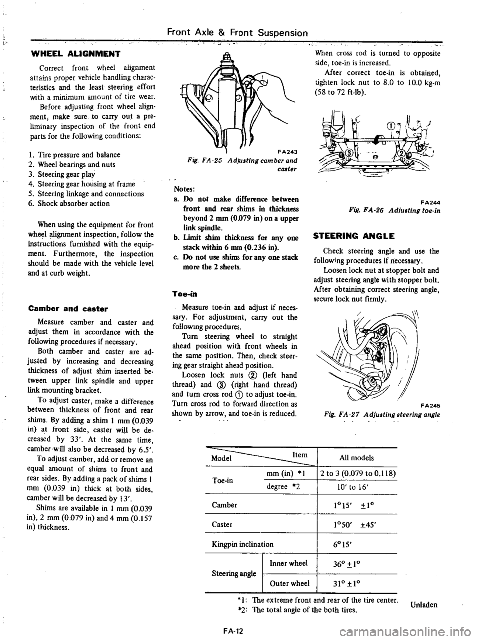
Model
Item
All
models
mOl
in
1
2
to
3
0
079
to
0
118
Toe
in
degree
2
10
to
16
Camber
lOIS
Io
Caster
10SO
4S
I
60IS
Kingpin
inc
inal10n
I
Inner
wheel
360
10
Steering
angle
I
Outer
wheel
310
10
1
The
extreme
front
and
rear
of
the
tire
center
Unladen
2
The
total
angle
of
the
both
tires
FA
12