DODGE CALIBER SRT 2008 1.G Owners Manual
Manufacturer: DODGE, Model Year: 2008, Model line: CALIBER SRT, Model: DODGE CALIBER SRT 2008 1.GPages: 373, PDF Size: 3 MB
Page 131 of 373
brake of the spinning wheel. This will allow more engine
torque to be applied to the wheel that is not spinning.
Brake Assist System (BAS)
The BAS is designed to optimize the vehicle's braking
capability during emergency braking maneuvers. The
system detects an emergency braking situation by sens-
ing the rate and amount of brake application and then
applies optimum pressure to the brakes. This can help
reduce braking distances. The BAS complements the
anti-lock brake system (ABS). Applying the brakes very
quickly results in the best BAS assistance. To receive the
benefit of the system, you must apply continuous brak-
ing pressure during the stopping sequence. Do not
reduce brake pedal pressure unless braking is no longer
desired. Once the brake pedal is released, the BAS is
deactivated.
WARNING!
²BAS cannot prevent the natural laws of physics
from acting on the vehicle, nor can it increase
braking efficiency beyond that afforded by the
condition of the vehicle brakes and tires or the
traction afforded.
²The BAS cannot prevent accidents, including
those resulting from excessive speed in turns,
following another vehicle too closely, or hydro-
planing. Only a safe, attentive, and skillful driver
can prevent accidents.
²The capabilities of a BAS-equipped vehicle must
never be exploited in a reckless or dangerous
manner which could jeopardize the user 's safety
or the safety of others.
130 UNDERSTANDING THE FEATURES OF YOUR VEHICLE
Page 132 of 373
ESP (Electronic Stability Program)
This system enhances directional control and stability of
the vehicle under various driving conditions. ESP cor-
rects for over/under steering of the vehicle by applying
the brake of the appropriate wheel to assist in counter-
acting the over/under steer condition. Engine power
may also be reduced to help the vehicle maintain the
desired path. ESP uses sensors in the vehicle to determine
the vehicle path intended by the driver and compares it
to the actual path of the vehicle. When the actual path
does not match the intended path, ESP applies the brake
of the appropriate wheel to assist in counteracting the
oversteer or understeer condition.
²Oversteer - when the vehicle is turning more than
appropriate for the steering wheel position.
²Understeer - when the vehicle is turning less than
appropriate for the steering wheel position.
ESP/TCS Indicator Light
The ªESP/TCS Indicator Lightº located in the instrument
cluster, starts to flash as soon as the tires lose traction and
the ESP system becomes active. The ªESP/TCS Indicator
Lightº also flashes when TCS is active. If the ªESP/TCS
Indicator Lightº begins to flash during acceleration, ease
up on the accelerator and apply as little throttle as
possible. Be sure to adapt your speed and driving to the
prevailing road conditions.
UNDERSTANDING THE FEATURES OF YOUR VEHICLE 131
3
Page 133 of 373
WARNING!
²Electronic Stability Program (ESP) cannot prevent
the natural laws of physics from acting on the
vehicle, nor can it increase the traction afforded by
prevailing road conditions.
²ESP cannot prevent accidents, including those
resulting from excessive speed in turns, driving on
very slippery surfaces, or hydroplaning. Only a
safe, attentive, and skillful driver can prevent
accidents.
²The capabilities of an ESP-equipped vehicle must
never be exploited in a reckless or dangerous
manner which could jeopardize the user's safety
or the safety of others.
ESP Operating Modes
The ESP system has 2 available operating modes.
ESP ON
This is the normal operating mode for ESP. Whenever the
vehicle is started the ESP system will be in this mode.
This mode should be used for most driving situations.
ESP should only be turned to ªPartial ESPº for specific
reasons as noted below.
PARTIAL ESP
This mode is entered by momentarily depressing the
ªESP OFFº button.
When in ªPartial ESPº mode, the TCS portion of ESP has
been disabled, the thresholds for ESP activation are
raised, and the ªESP/TCS Indicator Lightº will be illu-
minated. This mode is intended to be used for a more
spirited driving experience, or if the vehicle is in deep
snow, sand, or gravel conditions and more wheel spin
than ESP would normally allow is required.
132 UNDERSTANDING THE FEATURES OF YOUR VEHICLE
Page 134 of 373
To turn ESP on again, momentarily depress the
ªESP OFFº button.
WARNING!
In the Partial ESP mode, the engine torque reduction
and stability features are desensitized. Therefore, the
enhanced vehicle stability offered by ESP is
unavailable.
NOTE:To improve the vehicle's traction when driving
with snow chains, or starting off in deep snow, sand or
gravel, it may be desirable to switch to the ªPartial ESPº
mode by pressing the ªESP OFFº button. Once the
situation requiring ESP to be switched to the ªPartialESPº mode is overcome, turn ESP back on by momen-
tarily depressing the ªESP OFFº button. This may be
done while the vehicle is in motion.
ESP/BAS Warning Light and ESP/TCS Indicator
Light
The malfunction indicator for the ESP is combined with
the BAS indicator. The yellow ªESP/BAS Warning
Lampº and the yellow ªESP/TCS Indicator Lightº in the
instrument cluster both come on when the ignition
switch is turned to the ªONº position. They should both
go out with the engine running. If the ªESP/BAS Warn-
ing Lampº comes on continuously with the engine
running, a malfunction has been detected in either the
ESP or BAS system, or both. If this light remains on after
several ignition cycles, and the vehicle has been driven
several miles at speeds greater than 30 mph (48 km/h),
see your authorized dealer as soon as possible to have the
problem diagnosed and corrected.
UNDERSTANDING THE FEATURES OF YOUR VEHICLE 133
3
Page 135 of 373
NOTE:
²The ªESP Indicator Lightº and the ªESP/BAS Warning
Lightº come on momentarily each time the ignition
switch is turned ON.
²Each time the ignition is turned ON, the ESP System
will be ON even if it was turned off previously.
²The ESP Control System will make buzzing or clicking
sounds when it is active. This is normal; the sounds
will stop when ESP becomes inactive following the
maneuver that caused the ESP activation.
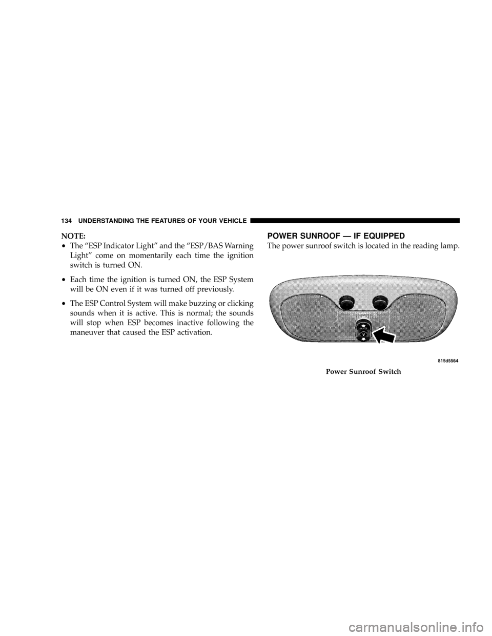
POWER SUNROOF Ð IF EQUIPPED
The power sunroof switch is located in the reading lamp.
Power Sunroof Switch
134 UNDERSTANDING THE FEATURES OF YOUR VEHICLE
Page 136 of 373
WARNING!
²Never leave children in a vehicle, with the keys in
the ignition switch. Occupants, particularly unat-
tended children, can become entrapped by the
power sunroof while operating the power sunroof
switch. Such entrapment may result in serious
injury or death.
²In an accident, there is a greater risk of being
thrown from a vehicle with an open sunroof. You
could also be seriously injured or killed. Always
fasten your seat belt properly and make sure all
passengers are properly secured too.
²Do not allow small children to operate the sun-
roof. Never allow fingers or other body parts, or
any object to project through the sunroof opening.
Injury may result.
Opening Sunroof Ð Manual
To open the sunroof, press and hold the switch rearward
to full open. Any release of the switch will stop the
movement and the sunroof will remain in a partial open
condition until the switch is pushed and held rearward
again.
Opening Sunroof Ð Express mode
By pressing the switch rearward and releasing, the sun-
roof will fully open from any position and stop at the end
of travel automatically. This is called Express Open.
During Express Open, any activation of the sunroof
switch will stop the sunroof.
Closing Sunroof Ð Manual
To close the sunroof, press and hold the switch in the
forward position. Again, any release of the switch will
stop the movement and the sunroof will remain in a
partial close condition until the switch is pushed and
UNDERSTANDING THE FEATURES OF YOUR VEHICLE 135
3
Page 137 of 373
held forward again. To ensure sunroof is fully closed,
press and hold switch until sunroof has completely
stopped moving.
Closing Sunroof Ð Express Mode
By pressing the switch forward and releasing, the sunroof
will fully close from any position and stop at the end of
travel automatically. This is called Express Close. During
Express Close, any activation of the sunroof switch will
stop the sunroof.
Pinch Protect Feature
This feature will detect an obstruction in the opening of
the sunroof during Express Close operation. If an ob-
struction in the path of the sunroof is detected, the
sunroof will automatically retract. Next, press the switch
forward and release to Express Close.
Pinch Protect Override
If a known obstruction (ice, debris, etc.) prevents closing,
press the switch forward and hold for two seconds after
the reversal occurs. This allows the sunroof to move
towards the close position.
NOTE:Pinch protection is disabled while the switch is
pressed.
Venting Sunroof Ð Express
Press and release the ªVº button, and the sunroof will
open to the vent position. This is called Express Vent, and
will occur regardless of the sunroof position. During
Express Vent operation, any movement of the switch will
stop the sunroof.
136 UNDERSTANDING THE FEATURES OF YOUR VEHICLE
Page 138 of 373
Sunshade Operation
The sunshade can be opened manually. However, the
sunshade will open automatically as the sunroof opens.
NOTE:The sunshade cannot be closed if the sunroof is
open.
Wind Buffeting
Wind buffeting can be described as the perception of
pressure on the ears or a helicopter-type sound in the
ears. Your vehicle may exhibit wind buffeting with the
windows down, or the sunroof (if equipped) in certain
open or partially open positions. This is a normal occur-
rence and can be minimized. If the buffeting occurs with
the rear windows open, open the front and rear windows
together to minimize the buffeting. If the buffeting occurs
with the sunroof open, adjust the sunroof opening to
minimize the buffeting or open any window.
Sunroof Maintenance
Use only a non-abrasive cleaner and a soft cloth to clean
the glass panel.
Ignition Off Operation
The sunroof will also operate up to 45 seconds after the
ignition has been turned off. The sunroof operation will
be canceled if either of the front doors are opened during
the accessory delay time or set accessory delay time.
UNDERSTANDING THE FEATURES OF YOUR VEHICLE 137
3
Page 139 of 373
ELECTRICAL POWER OUTLETS
There is a standard 12-Volt power outlet in the instru-
ment panel and a optional 115 Volt (150-Watts Maximum)
outlet in the center console for added convenience. These
outlets can power cell phones, electronics and other low
power devices.
NOTE:Due to overload protection the inverter will shut
down if the power rating is exceeded.WARNING!
To Avoid Serious Injury or Death:
²Donotusea3-Prong Adaptor.
²Do not insert any objects into the receptacles.
²Do not touch with wet hands.
²Close the lid when not in use, and while driving
the vehicle
²If this outlet is mishandled it may cause an electric
shock and failure.
138 UNDERSTANDING THE FEATURES OF YOUR VEHICLE
Page 140 of 373
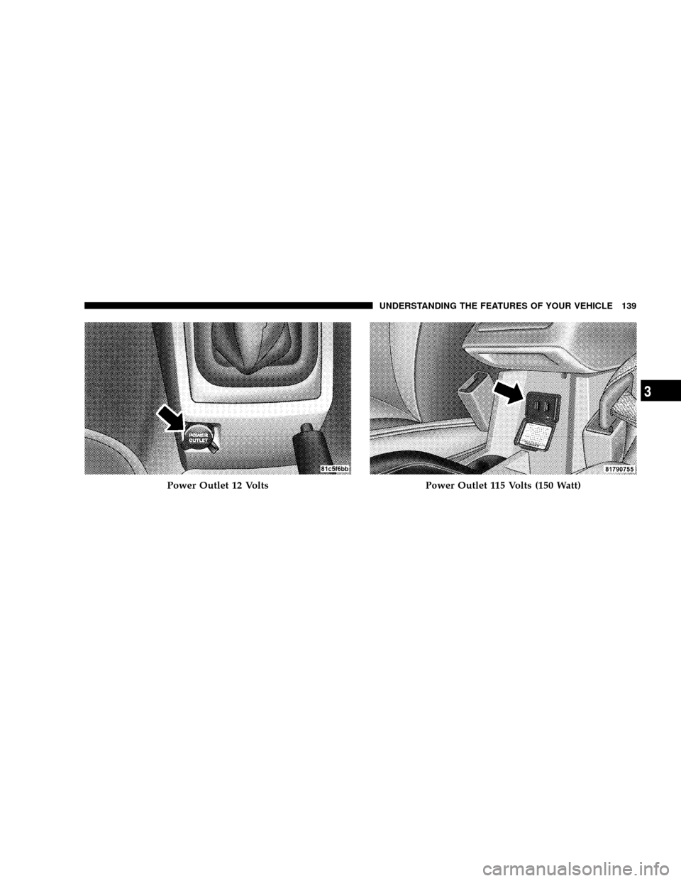
Power Outlet 12 VoltsPower Outlet 115 Volts (150 Watt)
UNDERSTANDING THE FEATURES OF YOUR VEHICLE 139
3