ECO mode DODGE JOURNEY 2020 Owners Manual
[x] Cancel search | Manufacturer: DODGE, Model Year: 2020, Model line: JOURNEY, Model: DODGE JOURNEY 2020Pages: 396, PDF Size: 25.53 MB
Page 4 of 396
2
INTRODUCTION
HOW TO USE THIS MANUAL .................................. 8
Essential Information .. .................................. 8
Symbols . ......................................................... 8
W
ARNINGS AND CAUTIONS . . ............................... 8
VEHICLE MODIFICATIONS/ALTERATIONS .. ........ 8
GETTING TO KNOW YOUR VEHICLE
KEYS ........................................................................ 9
Key Fob........................................................... 9
I
GNITION SWITCH . . ...............................................12
Keyless Push Button Ignition .. .................... 12
Ignition Or Accessory On Message . . .......... 14
REMOTE START — IF EQUIPPED . . .......................14
How To Use Remote Start .. ......................... 14
Remote Start Abort Message . . .................... 15
To Enter Remote Start Mode . . .................... 15
To Exit Remote Start Mode Without
Driving The Vehicle . .
................................... 15
To Exit Remote Start Mode And Drive
The Vehicle . .
................................................. 15
Remote Start Comfort System —
If Equipped . .
................................................. 16
General Information . . .................................. 16
SENTRY KEY . . .......................................................16
Key Programming .. ..................................... 17
Replacement Keys. . ..................................... 17
General Information . . .................................. 17 VEHICLE SECURITY ALARM — IF EQUIPPED .
.
... 18
To Arm The System .. .................................... 18
To Disarm The System . . .............................. 18
Rearming Of The System. . ........................... 19
Security System Manual Override . . ............ 19
Tamper Alert. . ............................................... 19
DOORS . ................................................................. 19
M anual Door Locks..
.................................... 19
Power Door Locks . . ..................................... 20
Keyless Enter-N-Go — Passive Entry
(If Equipped) . .
.............................................. 21
Child-Protection Door Lock System —
Rear Doors . .
................................................ 23
SEATS . ................................................................... 25
M anual Adjustment (Front Seats) .. ............ 25
Manual Adjustment (Rear Seats) . . ............. 26
Power Adjustment (Front Seat). . ................. 30
Front Heated Seats — If Equipped. . ............ 31
Seatback/Armrest — Second Row
Passenger Seat . .
.......................................... 32
HEAD RESTRAINTS . . ............................................ 32
Supplemental Active Head Restraints
(AHR) — Front Seats. .
................................... 33
Rear Head Restraint Adjustment. . .............. 34
Rear Head Restraint Removal . . .................. 35
STEERING WHEEL . . .............................................. 35
Tilt/Telescoping Steering Column .. ............ 35
Heated Steering Wheel — If Equipped . . .... 35MIRRORS .
.............................................................36
I
nside Day/Night Mirror — If Equipped .. ..... 36
Automatic Dimming Mirror — If Equipped . . . 37
Automatic Dimming Mirror With Rear View
Camera Display — If Equipped . .
................. 37
Outside Mirrors . . ......................................... 38
Interior Observation Mirror . . ...................... 38
Power Mirrors. . ............................................. 38
Heated Mirrors — If Equipped . . ................... 39
Power Folding Mirrors — If Equipped . . ....... 39
Illuminated Vanity Mirrors — If Equipped . . 40
EXTERIOR LIGHTS. . ...............................................40
Multifunction Lever .. ................................... 40
Headlights . ................................................... 40
D aytime Running Lights (DRLs) . . ................ 41
High/Low Beam Switch . . ............................. 41
Flash-To-Pass . . ............................................. 41
Automatic Headlights . . ............................... 41
Headlights On With Wipers (Available With
Automatic Headlights Only) . .
...................... 41
Headlight Time Delay . . ............................... 41
Lights-On Reminder . . ................................... 42
Fog Lights — If Equipped . . ........................... 42
Turn Signals . . .............................................. 42
Lane Change Assist — If Equipped . . ........... 42
INTERIOR LIGHTS . . ...............................................43
Courtesy/Interior Lighting .. ........................ 43
WIPERS AND WASHERS . . ..................................44
Windshield Wiper Operation .. ..................... 44
Rear Window Wiper/Washer . . ................... 46
Page 7 of 396
5
JACKING AND TIRE CHANGING........................ 199
Jack Location .. ...........................................199
Spare Tire Location And Removal . . ..........200
Preparations For Jacking. . .........................201
Jacking Instructions . . .................................201
Road Tire Installation . . ..............................205
Spare Tire Stowage. . ..................................206
JUMP STARTING ................................................ 2 0 6
Preparations For Jump Start .. ...................207
Jump Starting Procedure. . .........................208
IF YOUR ENGINE OVERHEATS . . ....................... 209
2.4L Engine — If Equipped .. ...................... 210
GEAR SELECTOR OVERRIDE . . .......................... 210
FREEING A STUCK VEHICLE .. ........................... 211
TOWING A DISABLED VEHICLE .. ...................... 212
Front-Wheel Drive (FWD) Models.. ............213
Tow Eye Usage — If Equipped . . ................213
ENHANCED ACCIDENT RESPONSE
SYSTEM (EARS) . .
............................................... 215
EVENT DATA RECORDER (EDR) .. ..................... 215
SERVICING AND MAINTENANCE
SCHEDULED SERVICING ................................... 216
Maintenance Plan.. ....................................217
ENGINE COMPARTMENT . . ................................ 220
2.4L Engine .. ..............................................220
Checking Oil Level . . ................................... 221
Adding Washer Fluid . . ...............................221
Maintenance-Free Battery . . ...................... 221
Pressure Washing . . ....................................222 DEALER SERVICE .
.
............................................222
Engine Oil .................................................. 223
E ngine Oil Filter . . ........................................ 224
Engine Air Cleaner Filter . . ......................... 224
Air Conditioner Maintenance . . ................. 224
Accessory Drive Belt Inspection . . ............. 225
Body Lubrication . . ...................................... 226
Windshield Wiper Blades . . ........................ 226
Exhaust System . . ...................................... 227
Cooling System . . ....................................... 228
Brake System . . .......................................... 232
Automatic Transmission. . .......................... 233
RAISING THE VEHICLE . . .....................................234
TIRES....................................................................234 T ire Safety Information .. ........................... 234
Tires — General Information . . .................. 242
Tire Types . .................................................. 246
S pare Tires — If Equipped . . ....................... 247
Wheel And Wheel Trim Care . . .................. 249
Tire Chains and Traction Devices . . ........... 250
Tire Rotation Recommendations . . ........... 251
DEPARTMENT OF TRANSPORTATION UNIFORM
TIRE QUALITY GRADES . .
...................................251
Treadwear .................................................. 251
T raction Grades . . ....................................... 251
Temperature Grades . . ............................... 252
BODYWORK . . ...................................................... 252
Protection From Atmospheric Agents..
..... 252
Body And Underbody Maintenance . . ........ 253
Preserving The Bodywork . . ........................ 253INTERIORS .
.
....................................................... 254
Seats And Fabric Parts .. ............................ 254
Plastic And Coated Parts. . ......................... 254
Leather Parts . . ........................................... 255
Glass Surfaces . . ........................................ 255
Cleaning The Cupholders . . ....................... 255
TECHNICAL SPECIFICATIONS
IDENTIFICATION DATA ...................................... 256
Vehicle Identification Number .. ................ 256
BRAKE SYSTEM . . ............................................... 256
WHEEL AND TIRE TORQUE
SPECIFICATIONS ..
.............................................. 257
Torque Specifications.. .............................. 257
FUEL REQUIREMENTS . . .................................... 257
Reformulated Gasoline .. .......................... 258
Materials Added To Fuel . . ......................... 258
Gasoline/Oxygenate Blends . . ................... 258
Do Not Use E-85 In Non-Flex Fuel
Vehicles . ..................................................... 259
C
NG And LP Fuel System Modifications . . 259
MMT In Gasoline. . ...................................... 259
Fuel System Cautions. . .............................. 259
Carbon Monoxide Warnings. . .................... 260
FLUID CAPACITIES . . ........................................... 261
FLUIDS AND LUBRICANTS .. .............................. 262
Engine ....................................................... 262
C hassis . ..................................................... 264
Page 9 of 396
7
INTRODUCTION
Dear Customer,
Congratulations on selecting your new vehicle. Be assured that it represents precision workmanship, distinctive styling, and high quality. This Owner's
Ma
nual has been prepared with the assistance of service and engineering specialists to acquaint you with the operation and maintenance of your
vehicle. It is supplemented by customer-oriented documents. Within this information, you will find a description of the services that FCA US LLC offers
to its customers as well as the details of the terms and conditions for maintaining its validity. Please take the time to read all of these publications
carefully before driving your vehicle for the first time. Following the instructions, recommendations, tips, and important warnings in this manual will help
assure safe and enjoyable operation of your vehicle.
This Owner's Manual describes all versions of this vehicle. Options and equipment dedicated to specific markets or versions are not expressly indicated in
t h
e text. Therefore, you should only consider the information which is related to the trim level, engine, and version that you have purchased. Any content
introduced throughout the Owner's Information, that may or may not be applicable to your vehicle, will be identified with the wording “If Equipped”. All data
contained in this publication are intended to help you use your vehicle in the best possible way. FCA US LLC aims at a constant improvement of the vehicles
produced. For this reason, it reserves the right to make changes to the model described for technical and/or commercial reasons. For further information,
contact an authorized dealer.
When it comes to service, remember that authorized dealers know your vehicle best, have factory-trained technicians and genuine MOPAR® parts, and
c a
re about your satisfaction.
1
Page 17 of 396
GETTING TO KNOW YOUR VEHICLE 15
REMOTE START ABORT MESSAGE
The following messages will appear in the
instrument cluster display if the vehicle fails to
remote start or exits remote start prematurely if
equipped with Remote Start:
Remote Start Cancelled — Door Open
Remote Start Cancelled — Hood Open
Remote Start Cancelled — Fuel Low
Remote Start Cancelled — L/Gate Open
Remote Start Disabled — Start Vehicle To
Reset The message stays active until the ignition is
p
l
aced in the ON/RUN position.
TO ENTER REMOTE START MODE
Push and release the remote start button on the
key fob twice within five seconds. The vehicle
doors will lock, the parking lights will flash and
the horn will chirp twice (if programmed). Then,
the engine will start and the vehicle will remain
in the Remote Start mode for a 15 minute cycle.
NOTE:
If an engine fault is present or fuel level is
low, the vehicle will start and then shut down
in 10 seconds.
The park lamps will turn on and remain on
during Remote Start mode.
For security, power window and power
sunroof operation (if equipped) are disabled
when the vehicle is in the Remote Start
mode.
The engine can be started two consecutive
times (two 15 minute cycles) with the key
f o
b. However, the ignition must be placed in
the ON/RUN position before you can repeat
the start sequence for a third cycle.
TO EXIT REMOTE START MODE
W
ITHOUT DRIVING THE VEHICLE
Push and release the remote start button one
time or allow the engine to run for the entire
15 minute cycle.
NOTE:
To avoid unintentional shutdowns, the system
wi
ll disable for two seconds after receiving a
valid Remote Start request.
TO EXIT REMOTE START MODE AND
D
RIVE THE VEHICLE
Before the end of 15 minute cycle, push and
re
lease the unlock button on the key fob to
unlock the doors and disarm the vehicle
security alarm (if equipped). Then, prior to the
end of the 15 minute cycle, push and release
t h
e START/STOP ignition button.
NOTE:
The message “Push Start Button” will appear in
t h
e instrument cluster display until you push the
START/STOP ignition button.
WARNING!
Do not start or run an engine in a closed
garage or confined area. Exhaust gas
contains Carbon Monoxide (CO) which is
odorless and colorless. Carbon Monoxide is
poisonous and can cause serious injury or
death when inhaled.
Keep key fobs away from children. Opera -
tion of the Remote Start System, windows,
d o
or locks or other controls could cause
serious injury or death.
2
Page 29 of 396

GETTING TO KNOW YOUR VEHICLE 27
Forward And Rearward Adjustment
The control lever is on the outboard side of the
seat. Lift the lever to move the seat forward or
rearward. Release the lever once the seat is in
the desired position. Then, using body pressure,
move forward and rearward on the seat to be
sure that the seat adjusters have latched.
Manual Seat Adjustment
Recliner Adjustment
The recline lever is on the outboard side of the
seat. To recline the seatback, lean back, lift the
lever, position the seatback as desired, and
then release the lever. To return the seatback to
its normal upright position, lean back, lift the
lever, lean forward, and then release the lever
once the seatback is in the upright position.
Recline Lever
Do not allow people to ride in any area of
your vehicle that is not equipped with seats
and seat belts.
Be sure everyone in your vehicle is in a seat
and using a seat belt properly.
On seven passenger models, do not allow a
passenger to sit in a third row seat with the
second row seatback(s) folded flat. In a
collision, the passenger could slide under
-
neath the seat belt and be seriously or even
f a
tally injured.
WARNING! (Continued)
WARNING!
Adjusting a seat while the vehicle is moving is
dangerous. The sudden movement of the
seat could cause you to lose control. The seat
belt might not be adjusted properly and you
could be injured. Adjust any seat only while
the vehicle is parked.
WARNING!
Adjusting a seat while the vehicle is moving
is dangerous. The sudden movement of the
seat could cause you to lose control. The
seat belt might not be adjusted properly
and you could be injured. Adjust the seat
only while the vehicle is parked.
Do not ride with the seatback reclined so
that the shoulder belt is no longer resting
against your chest. In a collision you could
slide under the seat belt and be seriously or
even fatally injured. Use the recliner only
when the vehicle is parked.
2
Page 30 of 396
28 GETTING TO KNOW YOUR VEHICLE
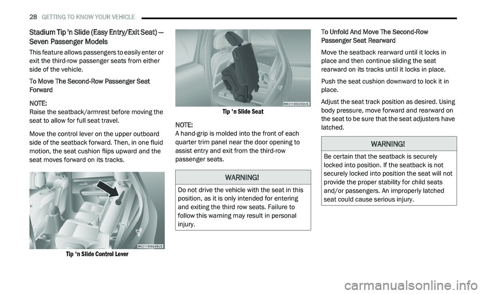
Stadium Tip 'n Slide (Easy Entry/Exit Seat) —
Seven Passenger Models
This feature allows passengers to easily enter or
exit the third-row passenger seats from either
side of the vehicle.
To Move The Second-Row Passenger Seat
Fo
rward
NOTE:
Raise the seatback/armrest before moving the
s e
at to allow for full seat travel.
Move the control lever on the upper outboard
s i
de of the seatback forward. Then, in one fluid
motion, the seat cushion flips upward and the
seat moves forward on its tracks.
Tip 'n Slide Control Lever Tip 'n Slide Seat
NOTE:
A hand-grip is molded into the front of each
q u
arter trim panel near the door opening to
assist entry and exit from the third-row
passenger seats. To Unfold And Move The Second-Row
P
a
ssenger Seat Rearward
Move the seatback rearward until it locks in
p l
ace and then continue sliding the seat
rearward on its tracks until it locks in place.
Push the seat cushion downward to lock it in
p l
ace.
Adjust the seat track position as desired. Using
b o
dy pressure, move forward and rearward on
the seat to be sure that the seat adjusters have
latched.
WARNING!
Do not drive the vehicle with the seat in this
position, as it is only intended for entering
and exiting the third row seats. Failure to
follow this warning may result in personal
injury.
WARNING!
Be certain that the seatback is securely
locked into position. If the seatback is not
securely locked into position the seat will not
provide the proper stability for child seats
and/or passengers. An improperly latched
seat could cause serious injury.
Page 34 of 396
32 GETTING TO KNOW YOUR VEHICLE
(Continued)
Vehicles Equipped With Remote Start
On models that are equipped with remote start,
th
e heated seats can be programmed to come
on during a remote start.
This feature can be programmed through the
U c
onnect system. Refer to “Uconnect Settings”
in “Multimedia” for further information.
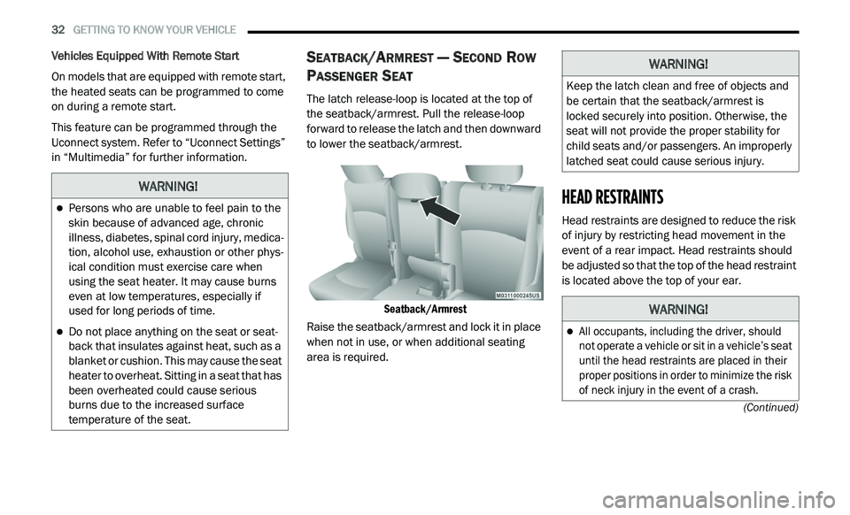
SEATBACK/ARMREST — SECOND ROW
P
ASSENGER SEAT
The latch release-loop is located at the top of
the seatback/armrest. Pull the release-loop
forward to release the latch and then downward
to lower the seatback/armrest.
Seatback/Armrest
Raise the seatback/armrest and lock it in place
w h
en not in use, or when additional seating
area is required.
HEAD RESTRAINTS
Head restraints are designed to reduce the risk
of injury by restricting head movement in the
event of a rear impact. Head restraints should
be adjusted so that the top of the head restraint
is located above the top of your ear.
WARNING!
Persons who are unable to feel pain to the
skin because of advanced age, chronic
illness, diabetes, spinal cord injury, medica -
tion, alcohol use, exhaustion or other phys -
ical condition must exercise care when
u s
ing the seat heater. It may cause burns
even at low temperatures, especially if
used for long periods of time.
Do not place anything on the seat or seat -
back that insulates against heat, such as a
b la
nket or cushion. This may cause the seat
heater to overheat. Sitting in a seat that has
been overheated could cause serious
burns due to the increased surface
temperature of the seat.
WARNING!
Keep the latch clean and free of objects and
be certain that the seatback/armrest is
locked securely into position. Otherwise, the
seat will not provide the proper stability for
child seats and/or passengers. An improperly
latched seat could cause serious injury.
WARNING!
All occupants, including the driver, should
not operate a vehicle or sit in a vehicle’s seat
until the head restraints are placed in their
proper positions in order to minimize the risk
of neck injury in the event of a crash.
Page 38 of 396
36 GETTING TO KNOW YOUR VEHICLE
The heated steering wheel control button is
located within the Uconnect system. You can
gain access to the control button through the
climate screen or the controls screen.
Press the heated steering wheel button
once to turn the heating element on.
Press the heated steering wheel button a
second time to turn the heating element off.
NOTE:
The engine must be running for the heated
s t
eering wheel to operate.
Vehicles Equipped With Remote Start
On models that are equipped with remote start,
t h
e heated steering wheel can be programmed
to come on during a remote start through the
Uconnect system. Refer to “Uconnect Settings”
in “Multimedia” for further information.
MIRRORS
INSIDE DAY/NIGHT MIRROR — IF
E
QUIPPED
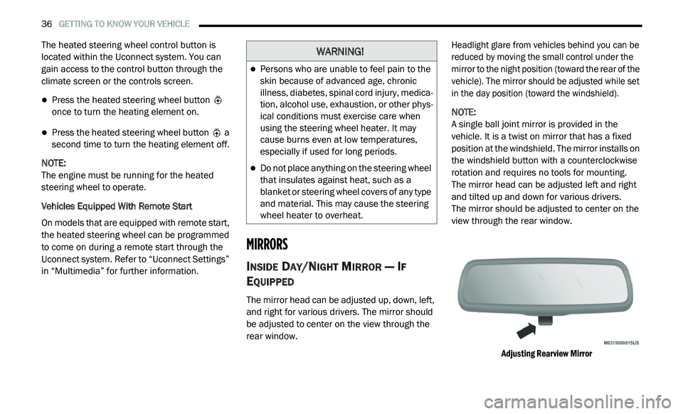
The mirror head can be adjusted up, down, left,
and right for various drivers. The mirror should
be adjusted to center on the view through the
rear window.
Headlight glare from vehicles behind you can be
r
e
duced by moving the small control under the
mirror to the night position (toward the rear of the
vehicle). The mirror should be adjusted while set
in the day position (toward the windshield).
NOTE:
A single ball joint mirror is provided in the
v e
hicle. It is a twist on mirror that has a fixed
position at the windshield. The mirror installs on
the windshield button with a counterclockwise
rotation and requires no tools for mounting.
The mirror head can be adjusted left and right
a n
d tilted up and down for various drivers.
The mirror should be adjusted to center on the
v i
ew through the rear window.
Adjusting Rearview Mirror
WARNING!
Persons who are unable to feel pain to the
skin because of advanced age, chronic
illness, diabetes, spinal cord injury, medica -
tion, alcohol use, exhaustion, or other phys -
ical conditions must exercise care when
u s
ing the steering wheel heater. It may
cause burns even at low temperatures,
especially if used for long periods.
Do not place anything on the steering wheel
that insulates against heat, such as a
blanket or steering wheel covers of any type
and material. This may cause the steering
wheel heater to overheat.
Page 41 of 396
GETTING TO KNOW YOUR VEHICLE 39
Models Without Express Window Feature
Push the mirror select button marked L (left) or
R
(right). Then, push one of the four arrow
buttons to move the mirror in the direction the
arrow is pointing.
Models With Express Window Feature
Push and release the mirror select button
m a
rked L (left) or R (right). Then, push one of
the four arrow buttons to move the mirror in the
direction the arrow is pointing. The selection
times out after 30 seconds of inactivity in order
to guard against accidentally changing a mirror
position following an adjustment.
NOTE:
A light in the selected button will illuminate indi -
cating the mirror is activated and can be
a d
justed.
HEATED MIRRORS — IF EQUIPPED
These mirrors are heated to melt frost
or ice. This feature will be activated
wh
enever you turn on the rear window
defroster (if equipped).
Refer to “Climate Controls” in this chapter for
f u
rther information.
POWER FOLDING MIRRORS — IF
E
QUIPPED
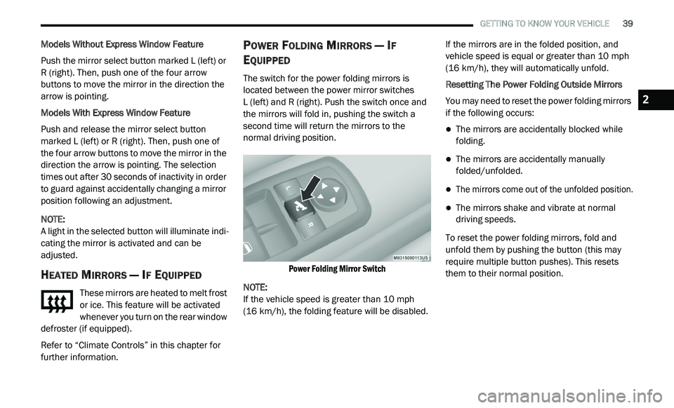
The switch for the power folding mirrors is
located between the power mirror switches
L (left) and R (right). Push the switch once and
t h
e mirrors will fold in, pushing the switch a
second time will return the mirrors to the
normal driving position.
Power Folding Mirror Switch
NOTE:
If the vehicle speed is greater than 10 mph
( 1
6 km/h), the folding feature will be disabled. If the mirrors are in the folded position, and
v
e
hicle speed is equal or greater than 10 mph
( 1
6 km/h), they will automatically unfold.
Resetting The Power Folding Outside Mirrors
You may need to reset the power folding mirrors
if
the following occurs:
The mirrors are accidentally blocked while
folding.
The mirrors are accidentally manually
folded/unfolded.
The mirrors come out of the unfolded position.
The mirrors shake and vibrate at normal
driving speeds.
To reset the power folding mirrors, fold and
u n
fold them by pushing the button (this may
require multiple button pushes). This resets
them to their normal position.
2
Page 43 of 396
GETTING TO KNOW YOUR VEHICLE 41
DAYTIME RUNNING LIGHTS (DRLS)
The Daytime Running Lights will turn on the first
time the vehicle is shifted out of PARK, and
remain on unless the parking brake is applied.
Upon returning to the PARK position, the DRLs
will turn off. DRLs will turn off when the ignition
is placed in the OFF position.
NOTE:
The DRLs can be turned on and off using the
Uconnect system, refer to “Uconnect Settings”
in “Multimedia” for further information.
On some vehicles, the Daytime Running
Lights may deactivate or reduce intensity on
one side of the vehicle (when a turn signal is
activated on that side), or on both sides of
the vehicle (when the hazard warning lights
are activated).
HIGH/LOW BEAM SWITCH
Push the multifunction lever away from you to
switch the headlights to high beam. Pull the
multifunction lever toward you to switch the
headlights back to low beam.
FLASH-TO-PASS
You can signal another vehicle with your
headlights by lightly pulling the multifunction
lever toward you. This will cause the high beam
headlights to turn on, and remain on, until the
lever is released.
AUTOMATIC HEADLIGHTS
This system automatically turns the headlights
on or off according to ambient light levels. To turn
the system on, rotate the headlight switch
counterclockwise to the AUTO position. When the
system is on, the headlight time delay feature is
also on. This means the headlights will stay on for
up to 90 seconds after you place the ignition in
the OFF position. The headlight time delay can be
programmed 0/30/60/90 seconds.
Refer to “Uconnect Settings” in “Multimedia”
fo
r further information.
To turn the automatic system off, move the
h e
adlight switch out of the AUTO position.
NOTE:
The engine must be running before the head -
lights will come on in the automatic mode.
HEADLIGHTS ON WITH WIPERS
(A
VAILABLE WITH AUTOMATIC
H
EADLIGHTS ONLY)
When this feature is active, the headlights will
turn on after the wipers are turned on if the
headlight switch is placed in the AUTO position
and programmable feature is set to on. In
addition, the headlights will turn off when the
wipers are turned off if they were turned on by
this feature.
NOTE:
The Headlights On with Wipers feature can be
t u
rned on or off using the Uconnect System.
Refer to “Uconnect Settings” in “Multimedia”
for further information.
HEADLIGHT TIME DELAY
This feature provides the safety of headlight
illumination for up to 90 seconds when leaving
your vehicle in an unlit area.
To activate the delay feature, place the ignition in
t h
e OFF position while the headlights are still on.
Then, turn off the headlights within 45 seconds.
The delay interval begins when the headlight
switch is turned off.
2