buttons DODGE JOURNEY 2020 Owners Manual
[x] Cancel search | Manufacturer: DODGE, Model Year: 2020, Model line: JOURNEY, Model: DODGE JOURNEY 2020Pages: 396, PDF Size: 25.53 MB
Page 11 of 396
9
GETTING TO KNOW YOUR VEHICLE
KEYS
KEY FOB
Your vehicle uses a keyless ignition system.
The ignition system consists of a key fob with
R e
mote Keyless Entry (RKE) and a START/STOP
push button ignition system. The Remote
Keyless Entry system consists of a key fob and
Keyless Enter-N-Go feature if equipped.
NOTE:
The key fob may not be found if it is located next
t o
a mobile phone, laptop or other electronic
device; these devices may block the key fob’s
wireless signal.
The Remote Keyless Entry key fob also contains
an
emergency key, which stores in the rear of
the key fob.
The emergency key allows for entry into the
v e
hicle should the battery in the vehicle or the
key fob become depleted. The emergency key is
also for locking the glove compartment. You can
keep the emergency key with you when valet
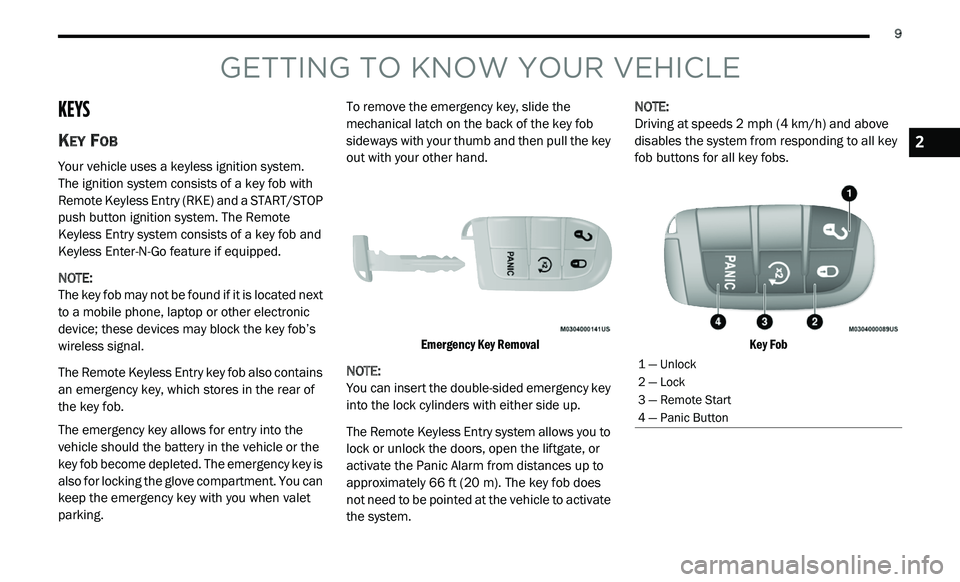
parking. To remove the emergency key, slide the
m
e
chanical latch on the back of the key fob
sideways with your thumb and then pull the key
out with your other hand.
Emergency Key Removal
NOTE:
You can insert the double-sided emergency key
in
to the lock cylinders with either side up.
The Remote Keyless Entry system allows you to
l o
ck or unlock the doors, open the liftgate, or
activate the Panic Alarm from distances up to
approximately 66 ft (20 m). The key fob does
n o
t need to be pointed at the vehicle to activate
the system. NOTE:
Driving at speeds 2 mph (4 km/h) and above
d i
sables the system from responding to all key
fob buttons for all key fobs.
Key Fob
1 — Unlock
2 — Lock
3 — Remote Start
4 — Panic Button
2
Page 23 of 396
GETTING TO KNOW YOUR VEHICLE 21
NOTE:
Use the Automatic Unlock Doors On Exit feature
i n
accordance with local laws.
KEYLESS ENTER-N-GO — PASSIVE
E
NTRY (IF EQUIPPED)
The Passive Entry system is an enhancement to
the vehicle’s Remote Keyless Entry (RKE)
system and a feature of Keyless Enter-N-Go.
This feature allows you to lock and unlock the
vehicle’s door(s) without having to push the key
fob lock or unlock buttons.
NOTE:
Passive Entry may be programmed on/off;
refer to “Uconnect Settings” in “Multimedia”
for further information.
If wearing gloves on your hands, or if it has
been raining/snowing on the Passive Entry
door handle, the unlock sensitivity can be
affected, resulting in a slower response time.
If the vehicle is unlocked by Passive Entry
and no door is opened within 60 seconds, the
vehicle will re-lock and if equipped will arm
the security alarm.
The key fob may not be detected by the
vehicle Passive Entry system if it is located
next to a mobile phone, laptop, or other elec -
tronic device; these devices may interfere
w i
th the key fob’s wireless signal and prevent
the Passive Entry system from locking/
unlocking the vehicle.
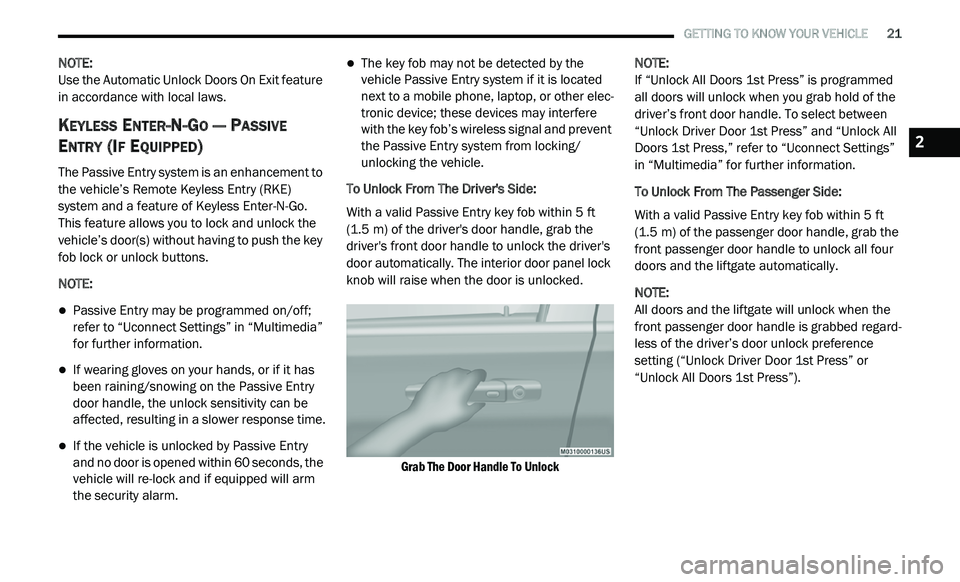
To Unlock From The Driver's Side:
With a valid Passive Entry key fob within 5 ft
( 1
.5 m) of the driver's door handle, grab the
d r
iver's front door handle to unlock the driver's
door automatically. The interior door panel lock
knob will raise when the door is unlocked.
Grab The Door Handle To Unlock
NOTE:
If “Unlock All Doors 1st Press” is programmed
a l
l doors will unlock when you grab hold of the
driver’s front door handle. To select between
“Unlock Driver Door 1st Press” and “Unlock All
Doors 1st Press,” refer to “Uconnect Settings”
in “Multimedia” for further information.
To Unlock From The Passenger Side:
With a valid Passive Entry key fob within 5 ft
( 1
.5 m) of the passenger door handle, grab the
f r
ont passenger door handle to unlock all four
doors and the liftgate automatically.
NOTE:
All doors and the liftgate will unlock when the
fr
ont passenger door handle is grabbed regard -
less of the driver’s door unlock preference
s e
tting (“Unlock Driver Door 1st Press” or
“Unlock All Doors 1st Press”).
2
Page 33 of 396
GETTING TO KNOW YOUR VEHICLE 31
direction of the switch. Release the switch when
the desired position has been reached.
Tilting The Seat Up Or Down
The angle of the seat cushion can be adjusted
in four directions. Pull upward or push
downward on the front or rear of the seat
switch; the front or rear of the seat cushion will
move in the direction of the switch. Release the
switch when the desired position is reached.
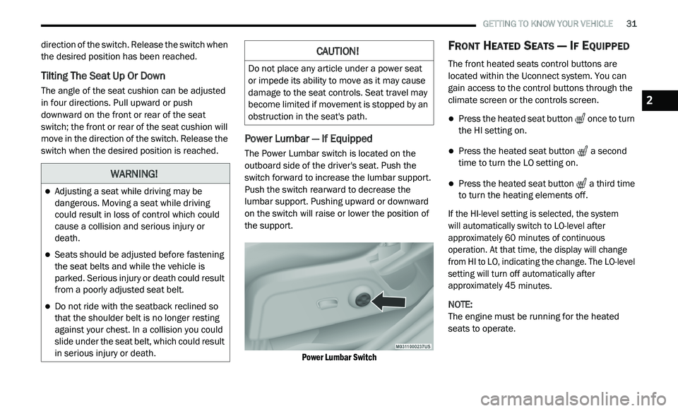
Power Lumbar — If Equipped
The Power Lumbar switch is located on the
outboard side of the driver's seat. Push the
switch forward to increase the lumbar support.
Push the switch rearward to decrease the
lumbar support. Pushing upward or downward
on the switch will raise or lower the position of
the support.
Power Lumbar Switch
FRONT HEATED SEATS — IF EQUIPPED
The front heated seats control buttons are
located within the Uconnect system. You can
gain access to the control buttons through the
climate screen or the controls screen.
Press the heated seat button once to turn
the HI setting on.
Press the heated seat button a second
time to turn the LO setting on.
Press the heated seat button a third time
to turn the heating elements off.
If the HI-level setting is selected, the system
will automatically switch to LO-level after
a p
proximately 60 minutes of continuous
o p
eration. At that time, the display will change
from HI to LO, indicating the change. The LO-level
setting will turn off automatically after
approximately 45 minutes.
NOTE:
The engine must be running for the heated
s e
ats to operate.
WARNING!
Adjusting a seat while driving may be
dangerous. Moving a seat while driving
could result in loss of control which could
cause a collision and serious injury or
death.
Seats should be adjusted before fastening
the seat belts and while the vehicle is
parked. Serious injury or death could result
from a poorly adjusted seat belt.
Do not ride with the seatback reclined so
that the shoulder belt is no longer resting
against your chest. In a collision you could
slide under the seat belt, which could result
in serious injury or death.
CAUTION!
Do not place any article under a power seat
or impede its ability to move as it may cause
damage to the seat controls. Seat travel may
become limited if movement is stopped by an
obstruction in the seat's path.
2
Page 37 of 396
GETTING TO KNOW YOUR VEHICLE 35
REAR HEAD RESTRAINT REMOVAL
To remove the head restraint, push the
adjustment and the release buttons while
pulling upward on the whole assembly and
raise it up as far as it can go. To reinstall the
h e
adrest, put the headrest posts into the holes
while pushing the release buttons. Then adjust
it to the appropriate height.
NOTE:
For proper routing of a Child Seat Tether, refer
t o
“Occupant Restraint Systems” in “Safety”.
STEERING WHEEL
TILT/TELESCOPING STEERING COLUMN
This feature allows you to tilt the steering
column upward or downward. It also allows
you to lengthen or shorten the steering column.
T h
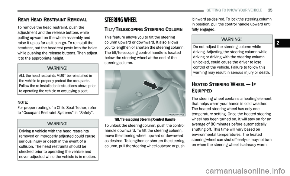
e tilt/telescoping control handle is located
below the steering wheel at the end of the
steering column.
Tilt/Telescoping Steering Control Handle
To unlock the steering column, push the control
h a
ndle downward. To tilt the steering column,
move the steering wheel upward or downward
as desired. To lengthen or shorten the steering
column, pull the steering wheel outward or push it inward as desired. To lock the steering column
in position, pull the control handle upward until
fully engaged.
HEATED STEERING WHEEL — IF
E
QUIPPED
The steering wheel contains a heating element
that helps warm your hands in cold weather.
The heated steering wheel has only one
temperature setting. Once the heated steering
wheel has been turned on, it will stay on for an
average of 80 minutes before automatically
s h
utting off. This time will vary based on
environmental temperatures. The heated
steering wheel can shut off early or may not turn
on when the steering wheel is already warm.
WARNING!
ALL the head restraints MUST be reinstalled in
the vehicle to properly protect the occupants.
Follow the re-installation instructions above prior
to operating the vehicle or occupying a seat.
WARNING!
Driving a vehicle with the head restraints
removed or improperly adjusted could cause
serious injury or death in the event of a
collision. The head restraints should be
checked prior to operating the vehicle and
never adjusted while the vehicle is in motion.
WARNING!
Do not adjust the steering column while
driving. Adjusting the steering column while
driving or driving with the steering column
unlocked, could cause the driver to lose
control of the vehicle. Failure to follow this
warning may result in serious injury or death.2
Page 41 of 396
GETTING TO KNOW YOUR VEHICLE 39
Models Without Express Window Feature
Push the mirror select button marked L (left) or
R
(right). Then, push one of the four arrow
buttons to move the mirror in the direction the
arrow is pointing.
Models With Express Window Feature
Push and release the mirror select button
m a
rked L (left) or R (right). Then, push one of
the four arrow buttons to move the mirror in the
direction the arrow is pointing. The selection
times out after 30 seconds of inactivity in order
to guard against accidentally changing a mirror
position following an adjustment.
NOTE:
A light in the selected button will illuminate indi -
cating the mirror is activated and can be
a d
justed.
HEATED MIRRORS — IF EQUIPPED
These mirrors are heated to melt frost
or ice. This feature will be activated
wh
enever you turn on the rear window
defroster (if equipped).
Refer to “Climate Controls” in this chapter for
f u
rther information.
POWER FOLDING MIRRORS — IF
E
QUIPPED
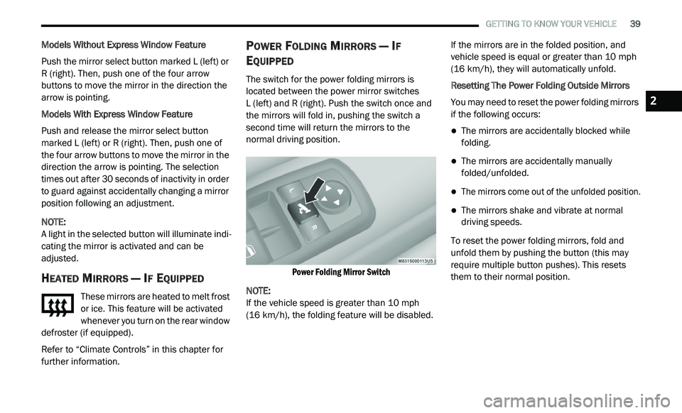
The switch for the power folding mirrors is
located between the power mirror switches
L (left) and R (right). Push the switch once and
t h
e mirrors will fold in, pushing the switch a
second time will return the mirrors to the
normal driving position.
Power Folding Mirror Switch
NOTE:
If the vehicle speed is greater than 10 mph
( 1
6 km/h), the folding feature will be disabled. If the mirrors are in the folded position, and
v
e
hicle speed is equal or greater than 10 mph
( 1
6 km/h), they will automatically unfold.
Resetting The Power Folding Outside Mirrors
You may need to reset the power folding mirrors
if
the following occurs:
The mirrors are accidentally blocked while
folding.
The mirrors are accidentally manually
folded/unfolded.
The mirrors come out of the unfolded position.
The mirrors shake and vibrate at normal
driving speeds.
To reset the power folding mirrors, fold and
u n
fold them by pushing the button (this may
require multiple button pushes). This resets
them to their normal position.
2
Page 51 of 396
GETTING TO KNOW YOUR VEHICLE 49
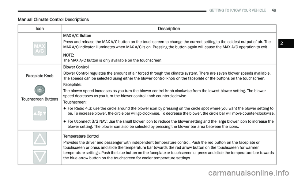
Manual Climate Control Descriptions
Icon Description
MAX A/C Button
Press and release the MAX A/C button on the touchscreen to change the current setting to the coldest output of air. The
MA
X A/C indicator illuminates when MAX A/C is on. Pressing the button again will cause the MAX A/C operation to exit.
NOTE:
The MAX A/C button is only available on the touchscreen.
Faceplate Knob
Touchscreen Buttons Blower Control
Blower Control regulates the amount of air forced through the climate system. There are seven blower speeds available.
T
h
e speeds can be selected using either the blower control knob on the faceplate or the buttons on the touchscreen.
Faceplate:
The blower speed increases as you turn the blower control knob clockwise from the lowest blower setting. The blower
s p
eed decreases as you turn the blower control knob counterclockwise.
Touchscreen:
For Radio 4.3: use the circle around the blower icon by pressing on the circle spot where you want the blower setting to
be. To increase blower, the circle bar will go clockwise. To decrease the blower, the circle bar will move counter-clockwise.
For Uconnect 3/3 NAV: Use the small blower icon to reduce the blower setting and the large blower icon to increase the
blo
wer setting. The blower can also be selected by pressing the blower bar area between the icons.
Temperature Control
Provides the driver and passenger with independent temperature control. Push the red button on the faceplate or
t o
uchscreen or press and slide the temperature bar towards the red arrow button on the touchscreen for warmer
temperature settings. Push the blue button on the faceplate or touchscreen or press and slide the temperature bar towards
the blue arrow button on the touchscreen for cooler temperature settings.
2
Page 52 of 396
50 GETTING TO KNOW YOUR VEHICLE
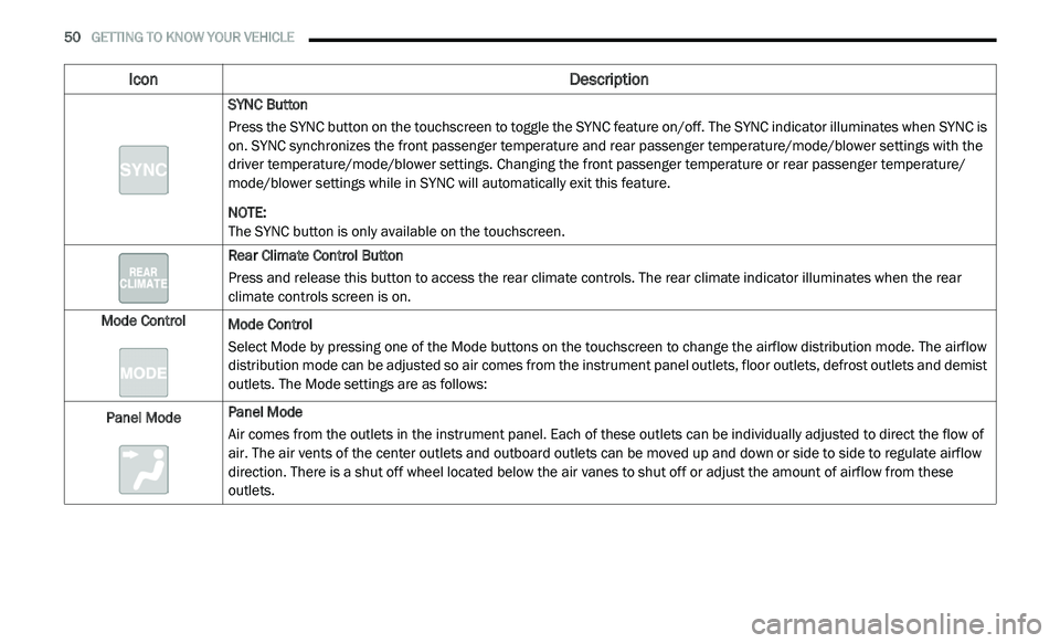
SYNC Button
Press the SYNC button on the touchscreen to toggle the SYNC feature on/off. The SYNC indicator illuminates when SYNC is
on
. SYNC synchronizes the front passenger temperature and rear passenger temperature/mode/blower settings with the
driver temperature/mode/blower settings. Changing the front passenger temperature or rear passenger temperature/
mode/blower settings while in SYNC will automatically exit this feature.
NOTE:
The SYNC button is only available on the touchscreen.
Rear Climate Control Button
Press and release this button to access the rear climate controls. The rear climate indicator illuminates when the rear
c li
mate controls screen is on.
Mode Control Mode Control
Select Mode by pressing one of the Mode buttons on the touchscreen to change the airflow distribution mode. The airflow
di
stribution mode can be adjusted so air comes from the instrument panel outlets, floor outlets, defrost outlets and demist
outlets. The Mode settings are as follows:
Panel Mode Panel Mode
Air comes from the outlets in the instrument panel. Each of these outlets can be individually adjusted to direct the flow of
ai
r. The air vents of the center outlets and outboard outlets can be moved up and down or side to side to regulate airflow
direction. There is a shut off wheel located below the air vanes to shut off or adjust the amount of airflow from these
outlets.
Icon Description
Page 56 of 396
54 GETTING TO KNOW YOUR VEHICLE
Icon Description
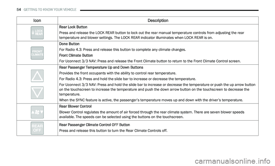
Rear Lock Button
Press and release the LOCK REAR button to lock out the rear manual temperature controls from adjusting the rear
te
mperature and blower settings. The LOCK REAR indicator illuminates when LOCK REAR is on.
Done Button
For Radio 4.3: Press and release this button to complete any climate changes.
Front Climate Button
For Uconnect 3/3 NAV: Press and release the Front Climate button to return to the Front Climate Control screen.
Rear Passenger Temperature Up and Down Buttons
Provides the front occupants with the ability to control rear temperature.
For Radio 4.3: Press and hold the slide bar to increase or decrease the temperature.
For Uconnect 3/3 NAV: Press and hold the slide bar to increase or decrease the temperature or push the up arrow button
o n
the touchscreen to increase the temperature and push the down arrow button on the touchscreen to decrease the
temperature.
When the SYNC feature is active, the passenger’s temperature moves up and down with the driver’s temperature.
Rear Blower Control
Blower Control regulates the amount of air forced through the rear climate system. There are seven blower speeds
av
ailable. The speeds can be selected using the buttons on the touchscreen.
Rear Passenger Climate Control OFF Button
Press and release this button to turn the Rear Climate Controls off.
Page 57 of 396
GETTING TO KNOW YOUR VEHICLE 55
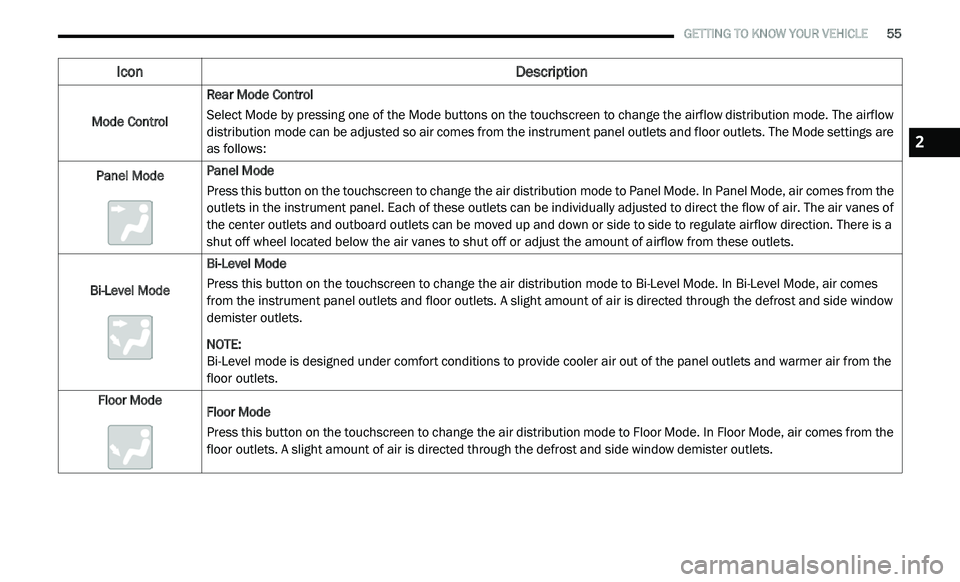
Mode Control Rear Mode Control
Select Mode by pressing one of the Mode buttons on the touchscreen to change the airflow distribution mode. The airflow
di
stribution mode can be adjusted so air comes from the instrument panel outlets and floor outlets. The Mode settings are
as follows:
Panel Mode Panel Mode
Press this button on the touchscreen to change the air distribution mode to Panel Mode. In Panel Mode, air comes from the
o
u
tlets in the instrument panel. Each of these outlets can be individually adjusted to direct the flow of air. The air vanes of
the center outlets and outboard outlets can be moved up and down or side to side to regulate airflow direction. There is a
shut off wheel located below the air vanes to shut off or adjust the amount of airflow from these outlets.
Bi-Level Mode Bi-Level Mode
Press this button on the touchscreen to change the air distribution mode to Bi-Level Mode. In Bi-Level Mode, air comes
f
r
om the instrument panel outlets and floor outlets. A slight amount of air is directed through the defrost and side window
demister outlets.
NOTE:
Bi-Level mode is designed under comfort conditions to provide cooler air out of the panel outlets and warmer air from the
fl
oor outlets.
Floor Mode Floor Mode
Press this button on the touchscreen to change the air distribution mode to Floor Mode. In Floor Mode, air comes from the
fl
oor outlets. A slight amount of air is directed through the defrost and side window demister outlets.
Icon Description
2
Page 59 of 396
GETTING TO KNOW YOUR VEHICLE 57
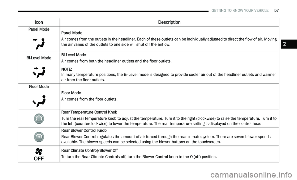
Panel Mode
Panel Mode
Air comes from the outlets in the headliner. Each of these outlets can be individually adjusted to direct the flow of air. Moving
th
e air vanes of the outlets to one side will shut off the airflow.
Bi-Level Mode Bi-Level Mode
Air comes from both the headliner outlets and the floor outlets.
NOTE:
In many temperature positions, the Bi-Level mode is designed to provide cooler air out of the headliner outlets and warmer
a i
r from the floor outlets.
Floor Mode Floor Mode
Air comes from the floor outlets.
Rear Temperature Control Knob
Turn the rear temperature knob to adjust the temperature. Turn it to the right (clockwise) to raise the temperature. Turn it to
th
e left (counterclockwise) to lower the temperature. The rear temperature setting is displayed on the control head.
Rear Blower Control Knob
Rear Blower Control regulates the amount of air forced through the rear climate system. There are seven blower speeds
a v
ailable. The blower speeds can be selected using the blower buttons on the touchscreen.
Rear Climate Control/Blower Off
To turn the Rear Climate Controls off, turn the Blower Control knob to the O (off) position.
Icon Description
2