sunroof DODGE NEON 1999 Service Owner's Manual
[x] Cancel search | Manufacturer: DODGE, Model Year: 1999, Model line: NEON, Model: DODGE NEON 1999Pages: 1200, PDF Size: 35.29 MB
Page 1082 of 1200
BODY
CONTENTS
page page
BODY COMPONENTS...................... 2
GENERAL SERVICE INFORMATION........... 1
PAINT................................. 41STATIONARY GLASS...................... 43
SUNROOF.............................. 47
GENERAL SERVICE INFORMATION
INDEX
page
GENERAL INFORMATION
SAFETY PRECAUTIONS AND WARNINGS...... 1
GENERAL INFORMATION
SAFETY PRECAUTIONS AND WARNINGS
WARNING: EYE PROTECTION SHOULD BE USED
WHEN SERVICING GLASS COMPONENTS. PER-
SONAL INJURY CAN RESULT.
USE A OSHA APPROVED BREATHING FILTER
WHEN SPRAYING PAINT OR SOLVENTS IN A CON-
FINED AREA. PERSONAL INJURY CAN RESULT.
AVOID PROLONGED SKIN CONTACT WITH
PETROLEUM OR ALCOHOL± BASED CLEANING
SOLVENTS. PERSONAL INJURY CAN RESULT.
DO NOT STAND UNDER A HOISTED VEHICLE
THAT IS NOT PROPERLY SUPPORTED ON SAFETY
STANDS. PERSONAL INJURY CAN RESULT.
CAUTION: When holes must be drilled or punched
in an inner body panel, verify depth of space to the
outer body panel, electrical wiring, or other compo-
nents. Damage to vehicle can result.
Do not weld exterior panels unless combustible
material on the interior of vehicle is removed from
the repair area. Fire or hazardous conditions, can
result.
Always have a fire extinguisher ready for use
when welding.
Disconnect the negative (-) cable clamp from the
battery when servicing electrical components that
are live when the ignition is OFF. Damage to electri-
cal system can result.Do not use abrasive chemicals or compounds on
painted surfaces. Damage to finish can result.
Do not use harsh alkaline based cleaning sol-
vents on painted or upholstered surfaces. Damage
to finish or color can result.
Do not hammer or pound on plastic trim panel
when servicing interior trim. Plastic panels can
break.
Chrysler Corporation uses many different types of
push-in fasteners to secure the interior and exterior
trim to the body. Most of these fasteners can be
reused to assemble the trim during various repair
procedures. At times, a push-in fastener cannot be
removed without damaging the fastener or the com-
ponent it is holding. If it is not possible to remove a
fastener without damaging a component or body, cut
or break the fastener and use a new one when
installing the component. Never pry or pound on a
plastic or pressed-board trim component. Using a
suitable fork-type prying device, pry the fastener
from the retaining hole behind the component being
removed. When installing, verify fastener alignment
with the retaining hole by hand. Push directly on or
over the fastener until it seats. Apply a low-force pull
to the panel to verify that it is secure.
When it is necessary to remove components to ser-
vice another, it should not be necessary to apply
excessive force or bend a component to remove it.
Before damaging a trim component, verify hidden
fasteners or captured edges holding the component in
place.
PLBODY 23 - 1
Page 1100 of 1200
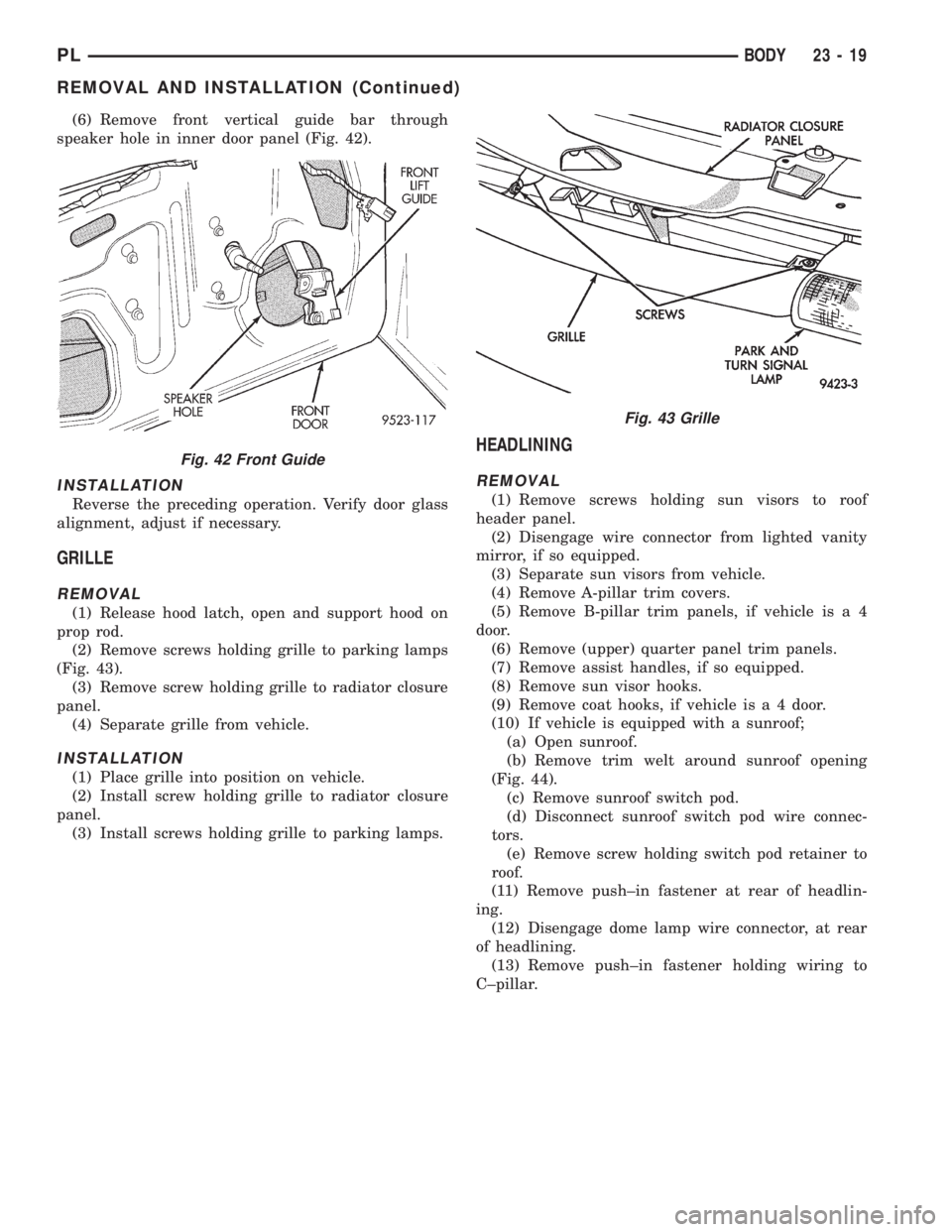
(6) Remove front vertical guide bar through
speaker hole in inner door panel (Fig. 42).
INSTALLATION
Reverse the preceding operation. Verify door glass
alignment, adjust if necessary.
GRILLE
REMOVAL
(1) Release hood latch, open and support hood on
prop rod.
(2) Remove screws holding grille to parking lamps
(Fig. 43).
(3) Remove screw holding grille to radiator closure
panel.
(4) Separate grille from vehicle.
INSTALLATION
(1) Place grille into position on vehicle.
(2) Install screw holding grille to radiator closure
panel.
(3) Install screws holding grille to parking lamps.
HEADLINING
REMOVAL
(1) Remove screws holding sun visors to roof
header panel.
(2) Disengage wire connector from lighted vanity
mirror, if so equipped.
(3) Separate sun visors from vehicle.
(4) Remove A-pillar trim covers.
(5) Remove B-pillar trim panels, if vehicle is a 4
door.
(6) Remove (upper) quarter panel trim panels.
(7) Remove assist handles, if so equipped.
(8) Remove sun visor hooks.
(9) Remove coat hooks, if vehicle is a 4 door.
(10) If vehicle is equipped with a sunroof;
(a) Open sunroof.
(b) Remove trim welt around sunroof opening
(Fig. 44).
(c) Remove sunroof switch pod.
(d) Disconnect sunroof switch pod wire connec-
tors.
(e) Remove screw holding switch pod retainer to
roof.
(11) Remove push±in fastener at rear of headlin-
ing.
(12) Disengage dome lamp wire connector, at rear
of headlining.
(13) Remove push±in fastener holding wiring to
C±pillar.
Fig. 42 Front Guide
Fig. 43 Grille
PLBODY 23 - 19
REMOVAL AND INSTALLATION (Continued)
Page 1101 of 1200
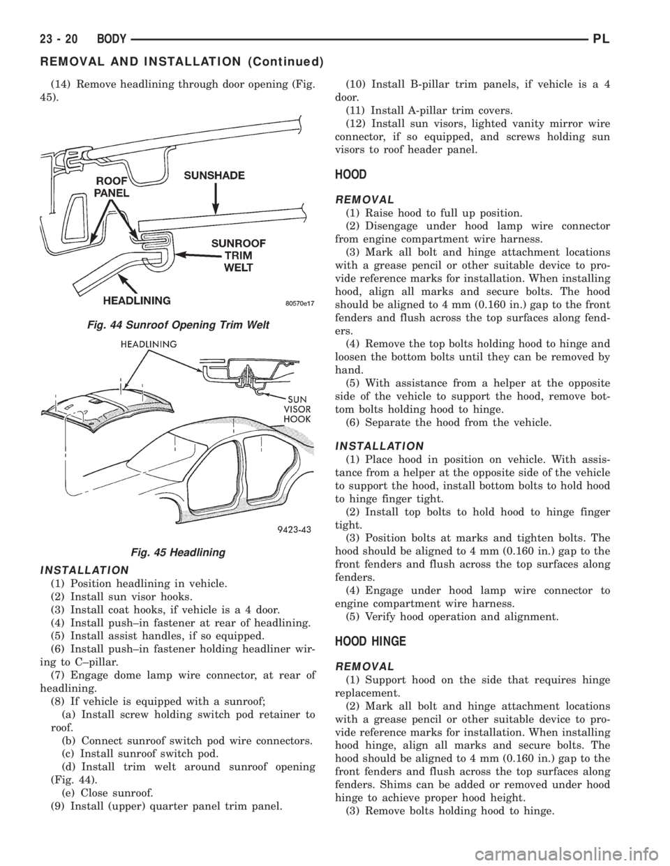
(14) Remove headlining through door opening (Fig.
45).
INSTALLATION
(1) Position headlining in vehicle.
(2) Install sun visor hooks.
(3) Install coat hooks, if vehicle is a 4 door.
(4) Install push±in fastener at rear of headlining.
(5) Install assist handles, if so equipped.
(6) Install push±in fastener holding headliner wir-
ing to C±pillar.
(7) Engage dome lamp wire connector, at rear of
headlining.
(8) If vehicle is equipped with a sunroof;
(a) Install screw holding switch pod retainer to
roof.
(b) Connect sunroof switch pod wire connectors.
(c) Install sunroof switch pod.
(d) Install trim welt around sunroof opening
(Fig. 44).
(e) Close sunroof.
(9) Install (upper) quarter panel trim panel.(10) Install B-pillar trim panels, if vehicle is a 4
door.
(11) Install A-pillar trim covers.
(12) Install sun visors, lighted vanity mirror wire
connector, if so equipped, and screws holding sun
visors to roof header panel.
HOOD
REMOVAL
(1) Raise hood to full up position.
(2) Disengage under hood lamp wire connector
from engine compartment wire harness.
(3) Mark all bolt and hinge attachment locations
with a grease pencil or other suitable device to pro-
vide reference marks for installation. When installing
hood, align all marks and secure bolts. The hood
should be aligned to 4 mm (0.160 in.) gap to the front
fenders and flush across the top surfaces along fend-
ers.
(4) Remove the top bolts holding hood to hinge and
loosen the bottom bolts until they can be removed by
hand.
(5) With assistance from a helper at the opposite
side of the vehicle to support the hood, remove bot-
tom bolts holding hood to hinge.
(6) Separate the hood from the vehicle.
INSTALLATION
(1) Place hood in position on vehicle. With assis-
tance from a helper at the opposite side of the vehicle
to support the hood, install bottom bolts to hold hood
to hinge finger tight.
(2) Install top bolts to hold hood to hinge finger
tight.
(3) Position bolts at marks and tighten bolts. The
hood should be aligned to 4 mm (0.160 in.) gap to the
front fenders and flush across the top surfaces along
fenders.
(4) Engage under hood lamp wire connector to
engine compartment wire harness.
(5) Verify hood operation and alignment.
HOOD HINGE
REMOVAL
(1) Support hood on the side that requires hinge
replacement.
(2) Mark all bolt and hinge attachment locations
with a grease pencil or other suitable device to pro-
vide reference marks for installation. When installing
hood hinge, align all marks and secure bolts. The
hood should be aligned to 4 mm (0.160 in.) gap to the
front fenders and flush across the top surfaces along
fenders. Shims can be added or removed under hood
hinge to achieve proper hood height.
(3) Remove bolts holding hood to hinge.
Fig. 44 Sunroof Opening Trim Welt
Fig. 45 Headlining
23 - 20 BODYPL
REMOVAL AND INSTALLATION (Continued)
Page 1128 of 1200
SUNROOF
INDEX
page page
DIAGNOSIS AND TESTING
DIAGNOSTIC PROCEDURES............... 47
SUNROOF DIAGNOSIS................... 47
REMOVAL AND INSTALLATION
SUNROOF CABLES...................... 48
SUNROOF COMPONENTS................ 49
SUNROOF DRIVE MOTOR................. 49
SUNROOF GLASS PANEL................. 49SUNROOF GUIDE AND MECHANISM
ASSEMBLY........................... 49
SUNROOF MODULE..................... 50
SUNROOF PROCEDURE INFORMATION...... 48
SUNROOF SUNSHADE................... 50
SUNROOF WIND DEFLECTOR............. 51
ADJUSTMENTS
SUNROOF GLASS HEIGHT ADJUSTMENT.... 51
DIAGNOSIS AND TESTING
DIAGNOSTIC PROCEDURES
Before beginning sunroof diagnostics verify that all
other power accessories are in proper operating con-
dition. If not, a common electrical problem may exist.
Refer to the Wiring Diagrams section of this publica-tion for circuit, splice and component descriptions.
Check the condition of the circuit protection (fuses,
circuit breakers or fuse links). Inspect all wiring con-
nector pins for proper engagement and continuity.
Check for battery voltage at the power sunroof con-
trol switches. If battery voltage is detected at the
control switches, proceed with the following tests.
SUNROOF DIAGNOSIS
SYMPTOM POSSIBLE CAUSE
Sunroof motor inoperative.²Contaminated or corroded slides and channels.
²Binding cable or linkage.
²Faulty circuit ground.
²Faulty power circuit to sunroof drive motor.
²Faulty sunroof drive motor.
²Faulty sunroof motor connector.
Audible whine when switch is depressed,
sunroof does not operate.²Faulty motor drive clutch.
²Binding linkage.
²Faulty sunroof motor connections.
Sunroof opens, but does not close.²Binding linkage.
²Faulty circuit.
²Faulty switch.
Sunroof vents, but does not open.²Binding linkage.
²Faulty circuit.
²Faulty switch.
Sunroof does not vent²Binding cable.
²Faulty circuit.
²Faulty switch.
Sunroof vents and opens but does not
close²Binding linkage.
²Faulty circuit.
²Faulty switch.
Sunroof water leak.²Drain tubes clogged or kinked.
²Glass panel improperly adjusted.
²Faulty glass panel seal.
PLBODY 23 - 47
Page 1129 of 1200
SYMPTOM POSSIBLE CAUSE
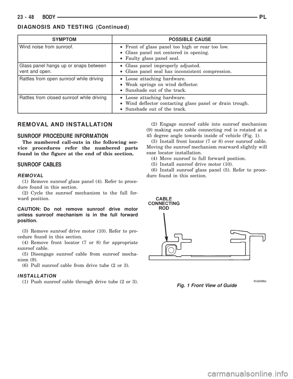
Wind noise from sunroof.²Front of glass panel too high or rear too low.
²Glass panel not centered in opening.
²Faulty glass panel seal.
Glass panel hangs up or snaps between
vent and open.²Glass panel improperly adjusted.
²Glass panel seal has inconsistent compression.
Rattles from open sunroof while driving²Loose attaching hardware.
²Weak springs on wind deflector.
²Sunshade out of the track.
Rattles from closed sunroof while driving²Loose attaching hardware.
²Wind deflector contacting glass panel or drain trough.
²Sunshade out of the track.
REMOVAL AND INSTALLATION
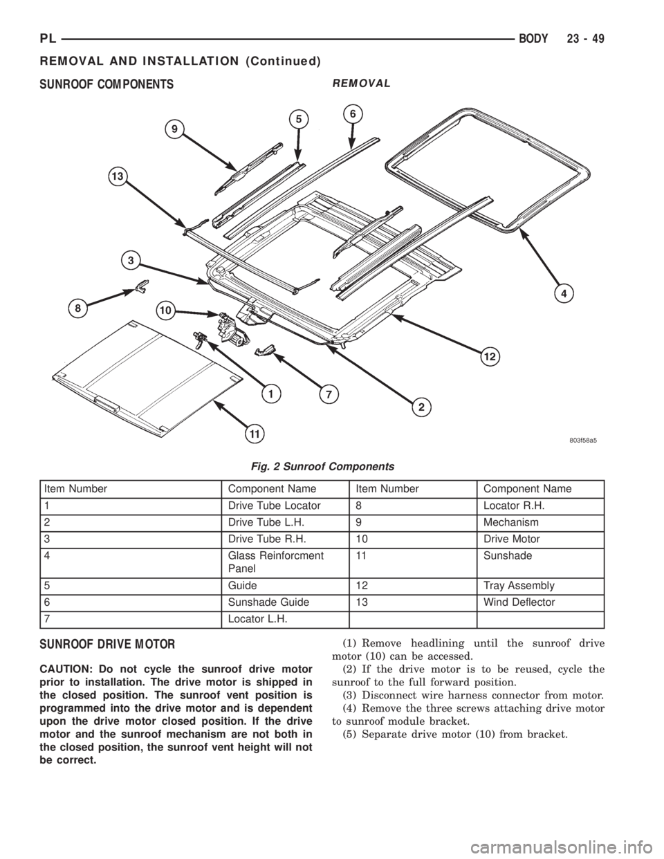
SUNROOF PROCEDURE INFORMATION
The numbered call-outs in the following ser-
vice procedures refer the numbered parts
found in the figure at the end of this section.
SUNROOF CABLES
REMOVAL
(1) Remove sunroof glass panel (4). Refer to proce-
dure found in this section.
(2) Cycle the sunroof mechanism to the full for-
ward position.
CAUTION: Do not remove sunroof drive motor
unless sunroof mechanism is in the full forward
position.
(3) Remove sunroof drive motor (10). Refer to pro-
cedure found in this section.
(4) Remove front locator (7 or 8) for appropriate
sunroof cable.
(5) Disengage sunroof cable from sunroof mecha-
nism (9).
(6) Pull sunroof cable from drive tube (2 or 3).
INSTALLATION
(1) Push sunroof cable through drive tube (2 or 3).(2) Engage sunroof cable into sunroof mechanism
(9) making sure cable connecting rod is rotated at a
45 degree angle towards inside of vehicle (Fig. 1).
(3) Install front locator (7 or 8) over sunroof cable.
Moving the sunroof mechanism rearward slightly will
ease locator installation.
(4) Move sunroof to full forward position.
(5) Install sunroof drive motor (10).
(6) Install sunroof glass panel (5). Refer to proce-
dure found in this section.Fig. 1 Front View of Guide
23 - 48 BODYPL
DIAGNOSIS AND TESTING (Continued)
Page 1130 of 1200
SUNROOF COMPONENTS
SUNROOF DRIVE MOTOR
CAUTION: Do not cycle the sunroof drive motor
prior to installation. The drive motor is shipped in
the closed position. The sunroof vent position is
programmed into the drive motor and is dependent
upon the drive motor closed position. If the drive
motor and the sunroof mechanism are not both in
the closed position, the sunroof vent height will not
be correct.
REMOVAL
(1) Remove headlining until the sunroof drive
motor (10) can be accessed.
(2) If the drive motor is to be reused, cycle the
sunroof to the full forward position.
(3) Disconnect wire harness connector from motor.
(4) Remove the three screws attaching drive motor
to sunroof module bracket.
(5) Separate drive motor (10) from bracket.
Fig. 2 Sunroof Components
Item Number Component Name Item Number Component Name
1 Drive Tube Locator 8 Locator R.H.
2 Drive Tube L.H. 9 Mechanism
3 Drive Tube R.H. 10 Drive Motor
4 Glass Reinforcment
Panel11 Sunshade
5 Guide 12 Tray Assembly
6 Sunshade Guide 13 Wind Deflector
7 Locator L.H.
PLBODY 23 - 49
REMOVAL AND INSTALLATION (Continued)
Page 1131 of 1200
INSTALLATION
(1) With the aid of a helper, hold the sunroof glass
panel in the closed position and engage the drive
motor (10) into the sunroof drive cables.
(2) Install screws holding drive motor to bracket.
(3) Connect wire harness to drive motor.
(4) Install headlining.
SUNROOF GLASS PANEL
REMOVAL
(1) Position sunroof sunshade (4) in full rearward
position.
(2) Remove six glass attachment screws.
(3) Push glass panel upward from underside until
glass panel clears the roof panel.
(4) Lift glass panel from vehicle.
INSTALLATION
(1) Position glass panel (4) in opening in vehicle
roof.
(2) Install, but do not tighten, glass attachment
screws.
(3) With the aid of a helper, hold the glass panel in
position and tighten glass attachment screws.
(4) Verify the correct glass height. Refer to Glass
Height Adjustment procedure in this section.
SUNROOF GUIDE AND MECHANISM ASSEMBLY
REMOVAL
(1) Remove sunroof glass panel (4). Refer to proce-
dure in this section.
(2) Remove front locator (7 or 8).
(3) Disengage cable from mechanism (9).
(4) Remove screws holding sunroof guide (5) and
mechanism (9) assembly to sunroof module.
(5) Lift assembly from module.
(6) Rotate assembly to disengage wind deflector
(13) from assembly.
INSTALLATION
(1) Engage wind deflector (13) into guide (5) and
mechanism (9) assembly.
(2) Position assembly onto module and install
screws holding assembly to sunroof module.
(3) Engage drive cable to mechanism.
(4) Install front locator (7 or 8 ). It may ease
installation to move sunroof mechanism slightly rear-
ward.
(5) Install sunroof glass panel. Refer to procedure
found in this section.
SUNROOF MODULE
REMOVAL
(1) Remove headlining.
(2) Remove fasteners attaching sunroof module to
vehicle roof and support braces.
(3) With the aid of a helper, separate sunroof mod-
ule from roof.
(4) Remove sunroof module from vehicle.
INSTALLATION
(1) With the aid of a helper, position sunroof mod-
ule in vehicle.
(2) Install fasteners holding sunroof module to
vehicle roof.
(3) Tighten all fasteners, starting from the front
and working rearward and then the motor bracket.
(4) Adjust glass panel for flushness to roof. Refer
to glass adjustment procedure in this section.
(5) Install headlining.
(6) Verify correct operation.
SUNROOF SUNSHADE
REMOVAL
(1) Remove sunroof glass panel (4). Refer to proce-
dure found in this section.
(2) Slide sunshade (11) to full forward position.
(3) Disengage slide blocks on one side of sunshade
from sunshade guide (6).
(4) Lift and pull sunshade out of opposite sun-
shade guide.
INSTALLATION
(1) Place sunshade with cloth side down and
install one side's slide blocks into the track on the
sunshade guide (6).
(2) Slide the other side's slide blocks to fully
inward position and insert them into the sunshade
guide (6).
(3) Verify that all four slide blocks are fully
engaged in the sunshade guide (6).
(4) Slide sunshade (11) fully rearward.
(5) Install sunroof glass panel (4). Refer to proce-
dure found in this section.
SUNROOF WIND DEFLECTOR
REMOVAL
(1) Open sunroof to full open position.
(2) Pull one end of wind deflector flap out of the
wind deflector beam (13).
(3) Release corner piece locking tab and separate
corner piece from wind deflector beam.
(4) Rotate corner piece outboard to release tab
from roof flange.
23 - 50 BODYPL
REMOVAL AND INSTALLATION (Continued)
Page 1132 of 1200
(5) Rotate corner piece to a vertical position and
pull it up through hole in guide (5).
(6) Repeat for other corner piece.
INSTALLATION
(1) Hold corner piece vertically and push tab down
through hole in guide (5).
(2) Rotate corner piece inward and place tab under
roof flange.
(3) Connect corner piece to wind deflector beam
(13).
(4) Install wind deflector flap into wind deflector
beam.
(5) Repeat for other corner piece.
ADJUSTMENTS
SUNROOF GLASS HEIGHT ADJUSTMENT
FLUSHNESS
(1) Position sunshade in full rearward position.
(2) To adjust front of glass;
(a) Loosen front and middle glass attachment
screws
(b) Adjust front of sunroof glass panel so that
the corners are flush to 1.0 mm below the top sur-
face of the roof panel.(c) Tighten all glass attachment screws.
(3) To adjust rear of glass;
(a) Loosen rear and middle glass attachment
screws
(b) Adjust rear of sunroof glass panel so that the
corners are flush to61.0 mm off the top surface of
the roof panel.
(c) Tighten all glass attachment screws.
VENT HEIGHT
(1) Cycle the sunroof module to vent position using
the drive motor.
(2) Check glass height in tilt using the appropriate
measuring tool.
(3) If the vent height is greater than 35 mm, using
switch slowly set to correct height.
(4) After setting correct height, remove drive
motor.
(5) With the motor removed, use the switch to set
tilt by operating the gear to the full closed position.
(6) Using tilt switch only, operate the motor until
it comes to a full stop at tilt position.
(7) Install drive motor and verify correct operation.
PLBODY 23 - 51
REMOVAL AND INSTALLATION (Continued)