fuel system DODGE NEON 1999 Service Service Manual
[x] Cancel search | Manufacturer: DODGE, Model Year: 1999, Model line: NEON, Model: DODGE NEON 1999Pages: 1200, PDF Size: 35.29 MB
Page 483 of 1200

3010FUSE
15A
BLOCK
FUSE
F12
20
DG/WT
6C101
DG/WT20 F12
2
1
SOLENOID PURGE
EVAP/
CYCLE
DUTY
F12
20
DG/WT
TORQUE
CONVERTER
CLUTCH
SOLENOID
(ATX)
2 3
F12
20
DG/WT
7C160
F12
20
DG/WT
EGR
TRANSDUCER
SOLENOID
1 2
F12
18
DB/WT
F12
20
DB/WTF12
18
DB/WT
POWERTRAIN
CONTROL
MODULE C2
2040C279C168C1
K35
20
GY/YL
K54
20
OR/BKK52
20
PK/BK
TORQUE
CONVERTER
CLUTCH
SOLENOID
CONTROLEGR
SOLENOID
CONTROL DUTY
CYCLE
EVAP/
PURGE
SOLENOID
CONTROL
S109
S126
10
ST-RUN A21
FUSED
IGN.
(ST-RUN)
DB/WT20 F122.0L 1.8L (8W-11-14)(8W-11-3)
(8W-11-4)
(8W-11-14) (8W-10-10)
8W - 30 - 10 8W-30 FUEL/IGNITION SYSTEM
BUILT-UP-EXPORTPL
J988W-18257
Page 484 of 1200

2121FUSE
20A
5352
55 56
BATT A0
POWER
DISTRIBUTION
CENTER
3010FUSE
15A
10BLOCK
FUSE
F12
20
DG/WT
S109
F12
20
DG/WT
F12
18
DG/WT
ST-RUN A21
4
13
2
FUEL
PUMP
MODULE
G303 C1
74
FUEL
PUMP
RELAY
CONTROLK31
18
BR
5C105
A141
16
DG/WT
A141
18
DG/WT
SIGNAL SENSORLEVELFUEL
5C230
G4
18
DB
G4
20
DB
3C160
G4
20
DB
6C105
G4
20
DB
Z1
18
BKZ2
18
BK
23C2
MODULE CONTROL
POWERTRAINMODULE CONTROL
POWERTRAIN
FUEL
PUMP
RELAY
C210
INSTRUMENT
CLUSTER
71
G4
20
DB
6C101
22
LEVEL
SENSOR
SIGNAL
M
(8W-10-16)(8W-10-5)
(8W-10-6) (8W-11-14)(8W-11-2)
(8W-11-3)
(8W-11-4)
(8W-11-14)
(8W-15-12)
(8W-15-13) (8W-10-5) (8W-10-9)
(8W-40-6)
PL8W-30 FUEL/IGNITION SYSTEM 8W - 30 - 11
8258J988W-1
Page 485 of 1200

C277C13C2CLUSTER INSTRUMENT
8611C103
G12
22
TN/BK
G12
20
TN/BK
G21
22
GY/LB
G21
20
GY/LB
G3
22
BK/PK
G3
20
BK/PK
951
SWITCH PRESSURE
HIGH
A/C
G3
20
BK/PKC20
18
BR/OR
C20
20
BR/OR
1
2
13C160
RELAY FAN
STATE
SOLID
GENERATOR
K173
20
DG
K173
20
LGC28
18
DB/ORK20
18
DG
C15673C18C238C218C264C14C2
GENERATOR
LAMP
DRIVERTACHOMETER
SIGNALCHECK
ENGINE
LAMP
DRIVERA/C
SWITCH
SENSERADIATOR
FAN
PULSE
CONTROLA/C
COMPRESSOR
CLUTCH
RELAY
CONTROLGENERATOR
FIELD
DRIVER
MODULE CONTROL
POWERTRAIN (IN PDC) RELAY
CLUTCH
COMPRESSOR
A/C
A/C
SWITCH
SIGNAL
RELAY
CONTROL CHECK
ENGINE
LAMP TACHOMETER GENERATOR
LAMP
36
(8W-40-5)
(8W-40-6)
(8W-40-8)
(8W-42-5)
(8W-42-5)
(8W-20-2) (8W-42-2)
8W - 30 - 12 8W-30 FUEL/IGNITION SYSTEMPL
J988W-18259
Page 486 of 1200

2
(ATX) SWITCH
POSITION
NEUTRAL
PARK/
T41
18
BR/YL
T41
20
BR/YL
76C1
PARK
NEUTRAL/
POSITION
SWITCH
SENSE
MODULE CONTROL
POWERTRAIN
P/N
31(IN PDC)
RELAY
MOTOR
STARTER
ENGINE ST A41
S106
T41
18
BR/YL
(8W-21-2)
(8W-21-3)
(8W-21-4)(8W-10-9)
PL8W-30 FUEL/IGNITION SYSTEM 8W - 30 - 13
8260J988W-1
Page 487 of 1200

C14162C15C278C180C1MODULE CONTROL
POWERTRAIN
SPEED
CONTROL
SWITCH
SENSE SENSE SWITCHLAMPSTOP
(+) FEED SOLENOIDSCONTROLSPEED
V37
20
RD/LG
10C103
V37
22
RD/LG
1
2
43
Z12
20
BK/TN
K29
20
WT/PKV32
20
YL/RD
V32
20
YL/RD
8C160
3
412
V36
20
TN/RDV35
20
LG/RD
V40
20
WT/BR
SERVO CONTROL
SPEED
VEHICLE
Z1
20
BK
Z1
18
BK
S107
G101
3 2 140
4 ON 2 SET/COAST
3 RES/ACCEL VEHICLE
SPEED
CONTROL
SWITCH
1 CANCEL
0 OFF CLOCKSPRING
3
CLOCKSPRING
BK/TN20 Z10 2
S104
G102G202
Z12
18
BK/TN
DUMP
SOLENOID SPEED
CONTROL
VENT
SOLENOID
CONTROL
(-) (-)CONTROL SOLENOIDVACUUM CONTROLSPEED
STOP
LAMP
SWITCH
(8W-15-2)
(8W-15-3)
(8W-15-2)
(8W-15-3)(8W-15-4)
(8W-15-4)(8W-15-7)
(8W-15-8) (8W-30-15)
8W - 30 - 14 8W-30 FUEL/IGNITION SYSTEMPL
J988W-18261
Page 488 of 1200

62
MODULE CONTROL
POWERTRAINSTOP
LAMP
SWITCH
SENSE
25FUSE15A
25
BATT A0
26
2
16
5
K29
20
WT/PK
F32
18
PK/DB
SWITCH LAMP
STOPCENTER DISTRIBUTION
POWER
Z12
20
BK/TN
Z12
18
BK/TN
G102
S104
WT/TN20 L50
C1
2C105
S101
12
CONTROLLER
ANTI-LOCK
BRAKE
L50
18
WT/TN
L50
22
WT/TN
NO
CONNECTION
13C101
LHD RHD
WT/TN20 L50WT/TN18 L50
TO
S316
4
3
8C160
V32
20
YL/RD
C25 SPEED
CONTROL
SOLENOIDS
FEED
(+)
V32
20
YL/RD
3
SERVO CONTROL
SPEED
VEHICLE
V40
20
WT/BR
L50
22
WT/TN
1C309
EXCEPT BUILT-UP-EXPORT BUILT-UP-EXPORT
L50
20
WT/TN
1
LAMP STOP
MOUNTED
HIGH
CENTER
L50
20
WT/TN
2
SWITCH HAZARD
SIGNAL/
TURN
13C101
BUILT-UP-EXPORT EXCEPT
BUILT-UP-EXPORTL50
20
WT/TN
L50
20
WT/TN
(8W-10-14)
(8W-10-15)(8W-10-5)
(8W-10-5)
(8W-10-6)
(8W-15-4)(8W-35-2)
(8W-15-4)
(8W-51-8) (8W-30-14)
(8W-51-6)(8W-52-2)
PL8W-30 FUEL/IGNITION SYSTEM 8W - 30 - 15
8262J988W-1
Page 489 of 1200

12
SENSOR ENGINE
IMMOBILIZER
K24
20
GY/BKK240
20
GY
C14443C1
MODULE CONTROL
POWERTRAIN
K7
20
OR
K4
20
BK/LB
K4
20
BK/LB
S110
8V
SUPPLY GROUNDSENSOR
S123
K7
20
OR
K7
20
OR
5C161
CAMSHAFT
POSITION
SENSORVEHICLE
SPEED
SENSOR
11
CRANKSHAFT
POSITION
SENSOR
1
K7
20
ORK7
18
ORK7
20
OR
2C1703
4C1701
IMMOBILIZER
34
65
K241
20
GY/BKK240
20
GY
K7
20
ORK4
20
BK/LB
SIGNAL
IN OUTSIGNAL
8V
SUPPLYSENSOR
GROUND
(8W-70-3)
(8W-30-7) (8W-30-8) (8W-30-7)(8W-61-8)
8W - 30 - 16 8W-30 FUEL/IGNITION SYSTEM
BUILT-UP-EXPORTPL
J988W-18263
Page 715 of 1200
assure gasket rails are flat. Flatten rails with a ham-
mer on a heavy steel plate if required. Gasket sur-
faces must be free of oil and dirt. Make sure old
gasket material is removed from blind attaching
holes.
FORM-IN-PLACE GASKET APPLICATION
Assembling parts using a form-in-place gasket
requires care but it's easier then using precut gas-
kets.
MopartGasket Maker material should be applied
sparingly 1 mm (0.040 inch.) diameter or less of seal-
ant to one gasket surface. Be certain the material
surrounds each mounting hole. Excess material can
easily be wiped off. Components should be torqued in
place within 15 minutes. The use of a locating dowel
is recommended during assembly to prevent smear-
ing material off the location.
The MopartSilicone Rubber Adhesive Sealant gas-
ket material or equivalent should be applied in a con-
tinuous bead approximately 3 mm (0.120 inch) in
diameter. All mounting holes must be circled. For
corner sealing, a 3.17 or 6.35 mm (1/8 or 1/4 inch.)
drop is placed in the center of the gasket contact
area. Uncured sealant may be removed with a shop
towel. Components should be torqued in place while
the sealant is still wet to the touch (within 10 min-
utes). The usage of a locating dowel is recommended
during assembly to prevent smearing material off the
location.
CRANKSHAFT SPROCKET BOLT ACCESS PLUG
An Access plug is located in the right inner fender
shield. Remove the plug and insert the proper size
socket, extension and ratchet, when crankshaft rota-
tion is necessary.
ENGINE CORE PLUGS
REMOVAL
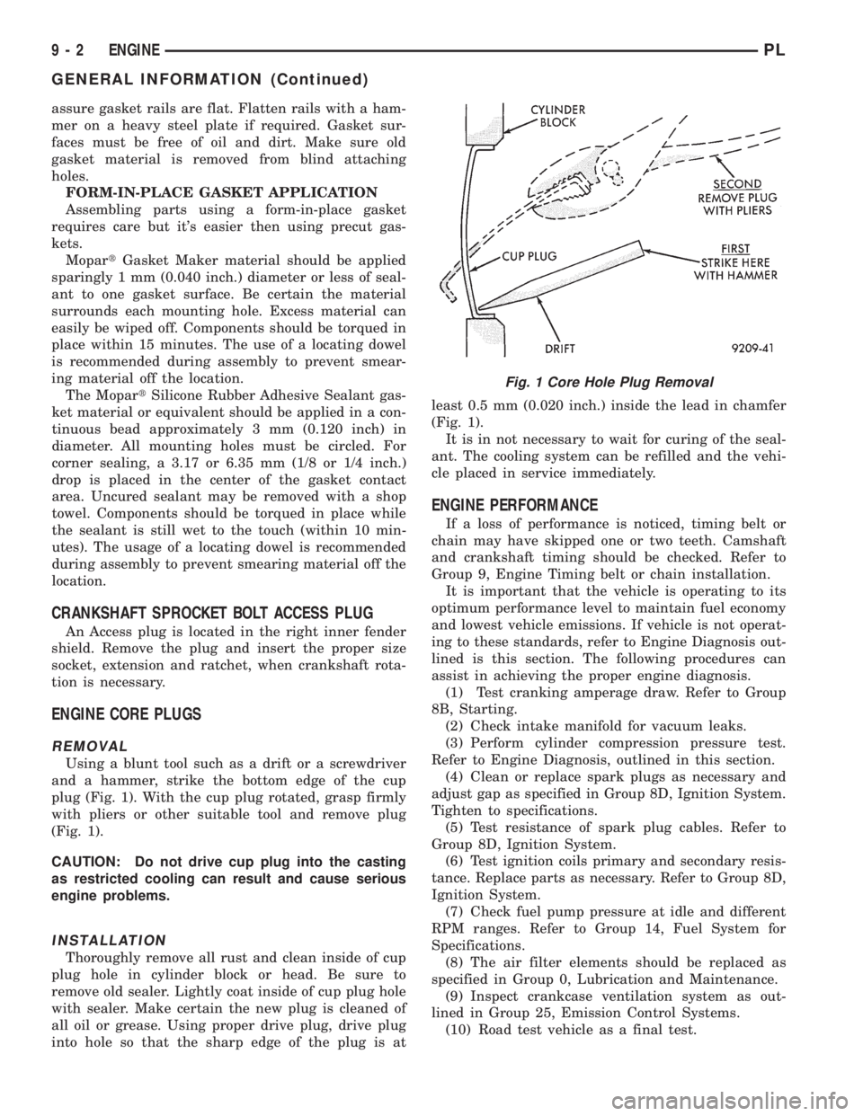
Using a blunt tool such as a drift or a screwdriver
and a hammer, strike the bottom edge of the cup
plug (Fig. 1). With the cup plug rotated, grasp firmly
with pliers or other suitable tool and remove plug
(Fig. 1).
CAUTION: Do not drive cup plug into the casting
as restricted cooling can result and cause serious
engine problems.
INSTALLATION
Thoroughly remove all rust and clean inside of cup
plug hole in cylinder block or head. Be sure to
remove old sealer. Lightly coat inside of cup plug hole
with sealer. Make certain the new plug is cleaned of
all oil or grease. Using proper drive plug, drive plug
into hole so that the sharp edge of the plug is atleast 0.5 mm (0.020 inch.) inside the lead in chamfer
(Fig. 1).
It is in not necessary to wait for curing of the seal-
ant. The cooling system can be refilled and the vehi-
cle placed in service immediately.
ENGINE PERFORMANCE
If a loss of performance is noticed, timing belt or
chain may have skipped one or two teeth. Camshaft
and crankshaft timing should be checked. Refer to
Group 9, Engine Timing belt or chain installation.
It is important that the vehicle is operating to its
optimum performance level to maintain fuel economy
and lowest vehicle emissions. If vehicle is not operat-
ing to these standards, refer to Engine Diagnosis out-
lined is this section. The following procedures can
assist in achieving the proper engine diagnosis.
(1) Test cranking amperage draw. Refer to Group
8B, Starting.
(2) Check intake manifold for vacuum leaks.
(3) Perform cylinder compression pressure test.
Refer to Engine Diagnosis, outlined in this section.
(4) Clean or replace spark plugs as necessary and
adjust gap as specified in Group 8D, Ignition System.
Tighten to specifications.
(5) Test resistance of spark plug cables. Refer to
Group 8D, Ignition System.
(6) Test ignition coils primary and secondary resis-
tance. Replace parts as necessary. Refer to Group 8D,
Ignition System.
(7) Check fuel pump pressure at idle and different
RPM ranges. Refer to Group 14, Fuel System for
Specifications.
(8) The air filter elements should be replaced as
specified in Group 0, Lubrication and Maintenance.
(9) Inspect crankcase ventilation system as out-
lined in Group 25, Emission Control Systems.
(10) Road test vehicle as a final test.
Fig. 1 Core Hole Plug Removal
9 - 2 ENGINEPL
GENERAL INFORMATION (Continued)
Page 720 of 1200
ENGINE DIAGNOSIS
INDEX
page page
DIAGNOSIS AND TESTING
CYLINDER COMBUSTION PRESSURE
LEAKAGE TEST........................ 8
CYLINDER COMPRESSION PRESSURE TEST . . 7
ENGINE DIAGNOSISÐMECHANICAL......... 11
ENGINE DIAGNOSISÐPERFORMANCE...... 10GENERAL INFORMATION.................. 7
INSPECTION (ENGINE OIL LEAKS IN
GENERAL)............................ 8
INTAKE MANIFOLD LEAKAGE DIAGNOSIS..... 7
LASH ADJUSTER (TAPPET) NOISE DIAGNOSIS.. 8
DIAGNOSIS AND TESTING
GENERAL INFORMATION
Engine diagnosis is helpful in determining the
causes of malfunctions.
These malfunctions may be classified as either
mechanical (e.g., a strange noise), or performance
(e.g., engine idles rough and stalls).
Refer to the Service DiagnosisÐMechanical Chart
and the Service DiagnosisÐPerformance Chart, for
possible causes and corrections of malfunctions. Refer
to Group 14, Fuel System, for the fuel system diag-
nosis.
Additional tests and diagnostic procedures may be
necessary for specific engine malfunctions that can-
not be isolated with the Service Diagnosis charts.
Information concerning additional tests and diagno-
sis is provided within the following:
²Cylinder Compression Pressure Test
²Cylinder Combustion Pressure Leakage Test
²Engine Cylinder Head Gasket Failure Diagnosis
²Intake Manifold Leakage Diagnosis
INTAKE MANIFOLD LEAKAGE DIAGNOSIS
An intake manifold air leak is characterized by
lower than normal manifold vacuum. Also, one or
more cylinders may not be functioning.
WARNING: USE EXTREME CAUTION WHEN THE
ENGINE IS OPERATING. DO NOT STAND IN A
DIRECT LINE WITH THE FAN. DO NOT PUT YOUR
HANDS NEAR THE PULLEYS, BELTS OR THE FAN.
DO NOT WEAR LOOSE CLOTHING.
(1) Start the engine.
(2) Spray a small stream of water (Spray Bottle) at
the suspected leak area.
(3) If a change in RPM'S, the area of the suspected
leak has been found.
(4) Repair as required.
CYLINDER COMPRESSION PRESSURE TEST
The results of a cylinder compression pressure test
can be utilized to diagnose several engine malfunc-
tions.
Ensure the battery is completely charged and the
engine starter motor is in good operating condition.
Otherwise the indicated compression pressures may
not be valid for diagnosis purposes.
(1) Check engine oil level and add oil if necessary.
(2) Drive the vehicle until engine reaches normal
operating temperature. Select a route free from traf-
fic and other forms of congestion, observe all traffic
laws, and accelerate through the gears several times
briskly.
(3) Remove all spark plugs from engine. As spark
plugs are being removed, check electrodes for abnor-
mal firing indicators fouled, hot, oily, etc. Record cyl-
inder number of spark plug for future reference.
(4) Disconnect coil wire from distributor and
secure to good ground to prevent a spark from start-
ing a fire (Conventional Ignition System). For Direct
Ignition System DIS disconnect the coil connector.
(5) Be sure throttle blade is fully open during the
compression check.
(6) Insert compression gage adaptor into the #1
spark plug hole in cylinder head. Crank engine until
maximum pressure is reached on gage. Record this
pressure as #1 cylinder pressure.
(7) Repeat the previous step for all remaining cyl-
inders.
(8) Compression should not be less than (689kPa)
100 psi and not vary more than 25 percent from cyl-
inder to cylinder.
(9) If one or more cylinders have abnormally low
compression pressures, repeat the compression test.
(10) If the same cylinder or cylinders repeat an
abnormally low reading on the second compression
test, it could indicate the existence of a problem in
the cylinder in question.The recommended com-
pression pressures are to be used only as a
guide to diagnosing engine problems. An engine
should not be disassembled to determine the
PLENGINE 9 - 7
Page 721 of 1200
cause of low compression unless some malfunc-
tion is present.
(11) Clean or replace spark plugs as necessary
and adjust gap as specified in Group 8, Electrical.
Tighten to specifications.
(12) Test resistance of spark plug cables. Refer to
Group 8, Electrical Ignition System Secondary Cir-
cuit Inspection.
(13) Test coil output voltage, primary and second-
ary resistance. Replace parts as necessary. Refer to
Group 8, Electrical Ignition System.
(14) Check fuel pump pressure at idle and differ-
ent RPM ranges. Refer to Group 14, Fuel System for
Specifications.
(15) The air filter elements should be replaced as
specified in Group 0, Lubrication and Maintenance,.
(16) Inspect crankcase ventilation system as out
lined in Group 0, Lubrication and Maintenance. For
emission controls see Group 25, Emission Controls
for service procedures.
(17) Inspect and adjust accessory belt drives refer-
ring to Group 7, Cooling System, Accessory Drive
Belts for proper adjustments.
(18) Road test vehicle as a final test.
CYLINDER COMBUSTION PRESSURE LEAKAGE
TEST
The combustion pressure leakage test provides an
accurate means for determining engine condition.
Combustion pressure leakage testing will detect:
²Exhaust and intake valve leaks (improper seat-
ing).
²Leaks between adjacent cylinders or into water
jacket.
²Any causes for combustion/compression pressure
loss.
WARNING: DO NOT REMOVE THE RADIATOR CAP
WITH THE SYSTEM HOT AND UNDER PRESSURE
BECAUSE SERIOUS BURNS FROM COOLANT CAN
OCCUR.
Check the coolant level and fill as required. DO
NOT install the radiator cap.
Start and operate the engine until it attains nor-
mal operating temperature, then turn the engine
OFF.
Clean spark plug recesses with compressed air.
Remove the spark plugs.
Remove the oil filler cap.
Remove the air cleaner.
Calibrate the tester according to the manufactur-
er's instructions. The shop air source for testing
should maintain 483 kPa (70 psi) minimum, 1 379
kPa (200 psi) maximum and 552 kPa (80 psi) recom-
mended.Perform the test procedures on each cylinder
according to the tester manufacturer's instructions.
While testing, listen for pressurized air escaping
through the throttle body, tailpipe and oil filler cap
opening. Check for bubbles in the radiator coolant.
All gauge pressure indications should be equal,
with no more than 25% leakage.
FOR EXAMPLE:At 552 kPa (80 psi) input pres-
sure, a minimum of 414 kPa (60 psi) should be main-
tained in the cylinder.
LASH ADJUSTER (TAPPET) NOISE DIAGNOSIS
A tappet-like noise may be produced from several
items. Check the following items.
(1) Engine oil level too high or too low. This may
cause aerated oil to enter the adjusters and cause
them to be spongy.
(2) Insufficient running time after rebuilding cylin-
der head. Low speed running up to 1 hour may be
required.
(3) During this time, turn engine off and let set for
a few minutes before restarting. Repeat this several
times after engine has reached normal operating
temperature.
(4) Low oil pressure.
(5) The oil restrictor pressed into the vertical oil
passage to the cylinder head is plugged with debris.
(6) Air ingested into oil due to broken or cracked
oil pump pick up.
(7) Worn valve guides.
(8) Rocker arm ears contacting valve spring
retainer.
(9) Rocker arm loose, adjuster stuck or at maxi-
mum extension and still leaves lash in the system.
(10) Faulty lash adjuster.
a. Check lash adjusters for sponginess while
installed in cylinder head. Depress part of rocker
arm over adjuster. Normal adjusters should feel very
firm. Spongy adjusters can be bottomed out easily.
b. Remove suspected rocker arms (sohc) or lash
adjuster (dohc) and replace.
INSPECTION (ENGINE OIL LEAKS IN GENERAL)
Begin with a through visual inspection of the
engine, particularly at the area of the suspected leak.
If an oil leak source is not readily identifiable, the
following steps should be followed:
(1) Do not clean or degrease the engine at this
time because some solvents may cause rubber to
swell, temporarily stopping the leak.
(2) Add an oil soluble dye (use as recommended by
manufacturer). Start the engine and let idle for
approximately 15 minutes. Check the oil dipstick to
make sure the dye is thoroughly mixed as indicated
with a bright yellow color under a black light.
9 - 8 ENGINEPL
DIAGNOSIS AND TESTING (Continued)