window DODGE NEON 1999 Service Workshop Manual
[x] Cancel search | Manufacturer: DODGE, Model Year: 1999, Model line: NEON, Model: DODGE NEON 1999Pages: 1200, PDF Size: 35.29 MB
Page 645 of 1200

CAV CIRCUIT FUNCTION
1 E2 220R FUSED PANEL LAMPS DIMMER SWITCH SIGNAL
2 Z2 22BK/LG GROUND
3 F20 22WT FUSED IGNITION SWITCH OUTPUT (RUN)
4 A4 14BK/RD FUSED B(+)
5 C15 14BK/WT REAR WINDOW DEFOGGER RELAY OUTPUT
BLACK
51
41
85
CAV CIRCUIT FUNCTION
1 P34 16PK/WT DOOR UNLOCK DRIVER
2 F35 16RD/YL FUSED B(+)
3 Z2 22BK/LG GROUND
4 D9 20DG RKE PROGRAM ENABLE
5 L4 14VT/WT DIMMER SWITCH LOW BEAM OUTPUT
6 M23 22YL/BK TIME DELAY RELAY
7 M1 22PK FUSED B(+)
8 G5 20DB/WT FUSED IGNITION SWITCH OUTPUT (ST-RUN)
BLACK
41
85
CAV CIRCUIT FUNCTION
1 P35 16OR/WT LEFT DOOR LOCK SWITCH OUTPUT
2 P36 16PK/VT LEFT DOOR UNLOCK SWITCH OUTPUT
3 P36 16PK/LB LEFT DOOR UNLOCK SWITCH OUTPUT
4 P35 16OR/VT LEFT DOOR LOCK SWITCH OUTPUT
5 L7 20BK/YL PARK LAMP SWITCH OUTPUT
6 X3 20BK/RD HORN RELAY CONTROL
7- -
8 P34 16PK/BK DOOR UNLOCK DRIVER
GRAY
8FRONT FOG LAMP FEED L35 20BR/RD 7
FUSED ILLUMINATION FEED E2 20OR 6
GROUND Z3 20BK/OR 5
HEADLAMP SWITCH FEED L2 14LG 4
REAR FOG LAMP FEED L38 18BR/WT 3
FOG LAMP FEED F61 18WT/OR 2
- - 1
FUNCTION CIRCUIT CAV
- - Z3 20BK/OR GROUND
5
8 1
NATURAL
REAR FOG
LAMP SWITCH
REAR WINDOW
DEFOGGER SWITCH
REMOTE KEYLESS
ENTRY (RKE)
MODULE - C1
REMOTE KEYLESS
ENTRY (RKE)
MODULE - C2 (BUILT-UP-EXPORT)
8W - 80 - 36 8W-80 CONNECTOR PIN-OUTSPL
J988W-1PL008036
Page 656 of 1200
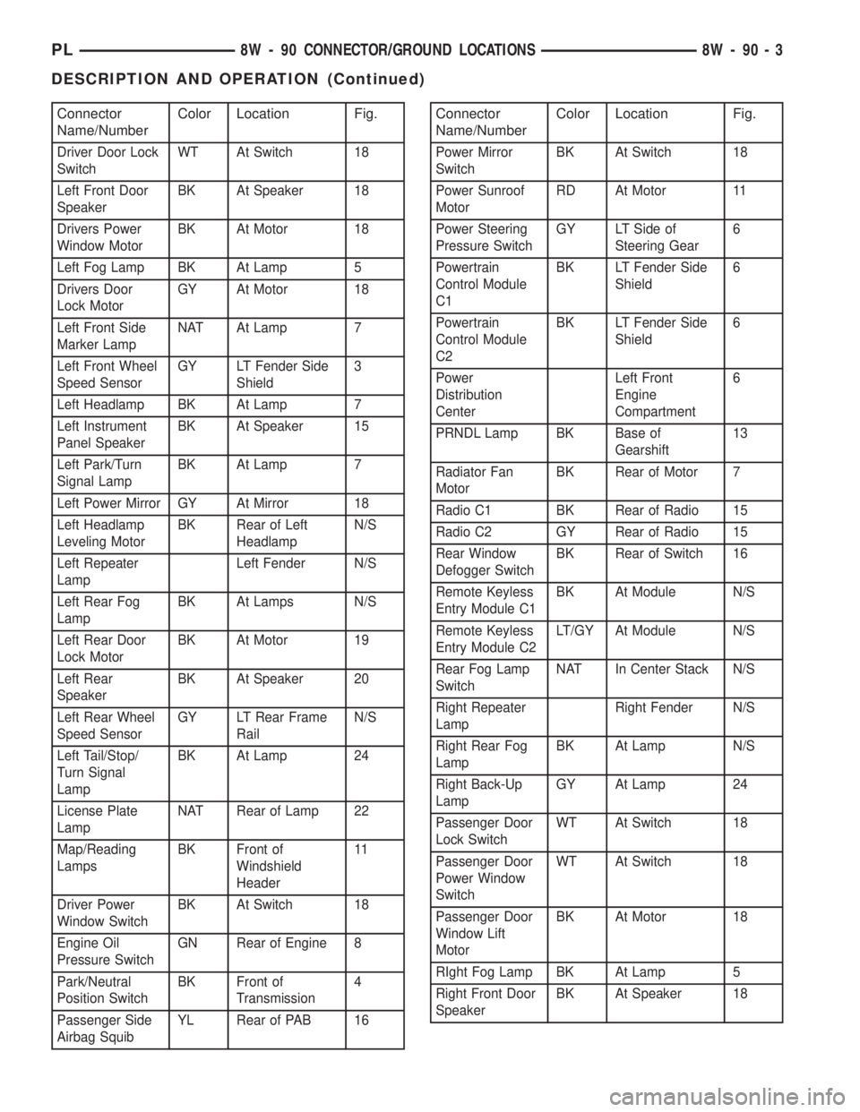
Connector
Name/NumberColor Location Fig.
Driver Door Lock
SwitchWT At Switch 18
Left Front Door
SpeakerBK At Speaker 18
Drivers Power
Window MotorBK At Motor 18
Left Fog Lamp BK At Lamp 5
Drivers Door
Lock MotorGY At Motor 18
Left Front Side
Marker LampNAT At Lamp 7
Left Front Wheel
Speed SensorGY LT Fender Side
Shield3
Left Headlamp BK At Lamp 7
Left Instrument
Panel SpeakerBK At Speaker 15
Left Park/Turn
Signal LampBK At Lamp 7
Left Power Mirror GY At Mirror 18
Left Headlamp
Leveling MotorBK Rear of Left
HeadlampN/S
Left Repeater
LampLeft Fender N/S
Left Rear Fog
LampBK At Lamps N/S
Left Rear Door
Lock MotorBK At Motor 19
Left Rear
SpeakerBK At Speaker 20
Left Rear Wheel
Speed SensorGY LT Rear Frame
RailN/S
Left Tail/Stop/
Turn Signal
LampBK At Lamp 24
License Plate
LampNAT Rear of Lamp 22
Map/Reading
LampsBK Front of
Windshield
Header11
Driver Power
Window SwitchBK At Switch 18
Engine Oil
Pressure SwitchGN Rear of Engine 8
Park/Neutral
Position SwitchBK Front of
Transmission4
Passenger Side
Airbag SquibYL Rear of PAB 16
Connector
Name/NumberColor Location Fig.
Power Mirror
SwitchBK At Switch 18
Power Sunroof
MotorRD At Motor 11
Power Steering
Pressure SwitchGY LT Side of
Steering Gear6
Powertrain
Control Module
C1BK LT Fender Side
Shield6
Powertrain
Control Module
C2BK LT Fender Side
Shield6
Power
Distribution
CenterLeft Front
Engine
Compartment6
PRNDL Lamp BK Base of
Gearshift13
Radiator Fan
MotorBK Rear of Motor 7
Radio C1 BK Rear of Radio 15
Radio C2 GY Rear of Radio 15
Rear Window
Defogger SwitchBK Rear of Switch 16
Remote Keyless
Entry Module C1BK At Module N/S
Remote Keyless
Entry Module C2LT/GY At Module N/S
Rear Fog Lamp
SwitchNAT In Center Stack N/S
Right Repeater
LampRight Fender N/S
Right Rear Fog
LampBK At Lamp N/S
Right Back-Up
LampGY At Lamp 24
Passenger Door
Lock SwitchWT At Switch 18
Passenger Door
Power Window
SwitchWT At Switch 18
Passenger Door
Window Lift
MotorBK At Motor 18
RIght Fog Lamp BK At Lamp 5
Right Front Door
SpeakerBK At Speaker 18
PL8W - 90 CONNECTOR/GROUND LOCATIONS 8W - 90 - 3
DESCRIPTION AND OPERATION (Continued)
Page 677 of 1200
Connector
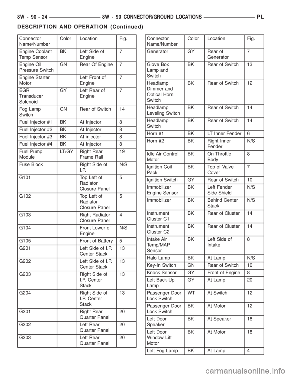
Name/NumberColor Location Fig.
Engine Coolant
Temp SensorBK Left Side of
Engine7
Engine Oil
Pressure SwitchGN Rear Of Engine 7
Engine Starter
MotorLeft Front of
Engine7
EGR
Transducer
SolenoidGY Left Rear of
Engine7
Fog Lamp
SwitchGN Rear of Switch 14
Fuel Injector #1 BK At Injector 8
Fuel Injector #2 BK At Injector 8
Fuel Injector #3 BK At injector 8
Fuel Injector #4 BK At Injector 8
Fuel Pump
ModuleLT/GY Right Rear
Frame Rail19
Fuse Block Right Side of
I.P.N/S
G101 Top Left of
Radiator
Closure Panel5
G102 Top Left of
Radiator
Closure Panel5
G103 Right Radiator
Closure Panel4
G104 Front Lower of
EngineN/S
G105 Front of Battery 5
G201 Left Side of I.P.
Center Stack13
G202 Left Side of I.P.
Center Stack13
G203 Right Side of
I.P. Center
Stack13
G204 Right Side of
I.P. Center
Stack13
G301 Right Rear
Quarter Panel20
G302 Left Rear
Quarter Panel20
G303 Left Rear
Quarter Panel20Connector
Name/NumberColor Location Fig.
Generator GY Rear of
Generator7
Glove Box
Lamp and
SwitchBK Rear of Switch 13
Headlamp
Dimmer and
Optical Horn
SwitchBK Rear of Switch 12
Headlamp
Leveling SwitchBK Rear of Switch 14
Headlamp
SwitchBK Rear of Switch 14
Horn #1 BK LT Inner Fender 6
Horn #2 BK Right Inner
FenderN/S
Idle Air Control
MotorBK On Throttle
Body8
Ignition Coil
PackBK Top of Valve
Cover7
Ignition Switch GY Rear of Switch 10
Immobilizer
Engine SensorBK Left Fender
Side ShieldN/S
Immobilizer BK Behind Center
StackN/S
Instrument
Cluster C1BK Rear of Cluster 14
Instrument
Cluster C2BK Rear of Cluster 14
Intake Air
Temp/MAP
SensorBK Left Side of
Intake8
Halo Lamp BK At Lamp N/S
Key-In Switch GN Rear of Switch 10
Knock Sensor GY Front of Engine 8
Left Back-Up
LampGY At Lamp 20
Passenger Door
Lock SwitchWT At Switch 12
Passenger Door
Lock SwitchBK At Motor 12
Left Door
SpeakerBK At Speaker 18
Left Door
Window Lift
MotorBK At Motor 18
Left Fog Lamp BK At Lamp 4
8W - 90 - 24 8W - 90 CONNECTOR/GROUND LOCATIONSPL
DESCRIPTION AND OPERATION (Continued)
Page 678 of 1200
Connector
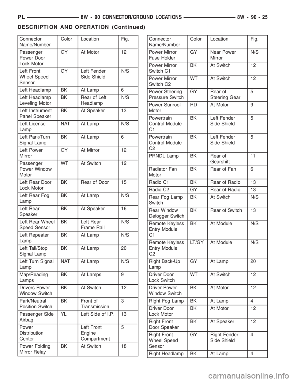
Name/NumberColor Location Fig.
Passenger
Power Door
Lock MotorGY At Motor 12
Left Front
Wheel Speed
SensorGY Left Fender
Side ShieldN/S
Left Headlamp BK At Lamp 6
Left Headlamp
Leveling MotorBK Rear of Left
HeadlampN/S
Left Instrument
Panel SpeakerBK At Speaker 13
Left License
LampNAT At Lamp N/S
Left Park/Turn
Signal LampBK At Lamp 6
Left Power
MirrorGY At Mirror 12
Passenger
Power Window
MotorWT At Switch 12
Left Rear Door
Lock MotorBK Rear of Door 15
Left Rear Fog
LampBK At Lamp N/S
Left Rear
SpeakerBK At Speaker 16
Left Rear Wheel
Speed SensorBK Left Rear
Frame RailN/S
Left Repeater
LampBK At Lamp N/S
Left Tail/Stop
Signal LampBK At Lamp 20
Left Turn Signal
LampNAT At Lamp N/S
Map/Reading
LampsBK At Lamps 9
Drivers Power
Window SwitchBK At Switch 12
Park/Neutral
Position SwitchBK Front of
Transmission3
Passenger Side
AirbagYL Left Side of I.P. 13
Power
Distribution
CenterLeft Front
Engine
Compartment5
Power Folding
Mirror RelayBK At Switch 18Connector
Name/NumberColor Location Fig.
Power Mirror
Fuse HolderGY Near Power
MirrorN/S
Power Mirror
Switch C1BK At Switch 12
Power Mirror
Switch C2WT At Switch 12
Power Steering
Pressure SwitchGY Rear of
Steering Gear5
Power Sunroof
MotorRD At Motor 9
Powertrain
Control Module
C1BK Left Fender
Side Shield5
Powertrain
Control Module
C2BK Left Fender
Side Shield5
PRNDL Lamp BK Rear of
Gearshift11
Radiator Fan
MotorBK Rear of Fan 6
Radio C1 BK Rear of Radio 13
Radio C2 GY Rear of Radio 13
Rear Fog Lamp
SwitchBK At Switch N/S
Rear Window
Defogger SwitchBK Rear of Switch 13
Remote Keyless
Entry Module
C1BK At Module N/S
Remote Keyless
Entry Module
C2LT/GY At Module N/S
Right Back-Up
LampGY At Lamp 20
Driver Door
Lock SwitchWT At Switch 12
Driver Power
Window SwitchBK At Motor 12
RIght Fog Lamp BK At Lamp 4
Driver Door
Lock MotorBK At Motor 12
Right Front
Door SpeakerBK At Speaker 12
Right Front
Wheel Speed
SensorGY Right Fender
Side Shield4
Right Headlamp BK At Lamp 4
PL8W - 90 CONNECTOR/GROUND LOCATIONS 8W - 90 - 25
DESCRIPTION AND OPERATION (Continued)
Page 839 of 1200
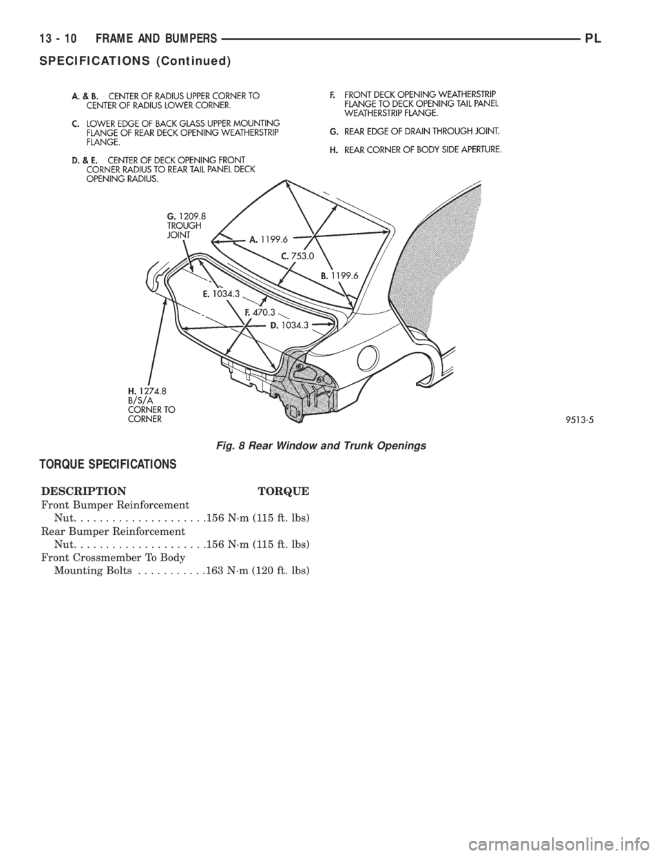
TORQUE SPECIFICATIONS
DESCRIPTION TORQUE
Front Bumper Reinforcement
Nut.....................156 N´m (115 ft. lbs)
Rear Bumper Reinforcement
Nut.....................156 N´m (115 ft. lbs)
Front Crossmember To Body
Mounting Bolts...........163 N´m (120 ft. lbs)
Fig. 8 Rear Window and Trunk Openings
13 - 10 FRAME AND BUMPERSPL
SPECIFICATIONS (Continued)
Page 852 of 1200
The hose clamps have rolled edges to prevent the
clamp from cutting into the hose. Only use clamps
that are original equipment or equivalent. Other
types of clamps may cut into the hoses and cause
high pressure fuel leaks. Tighten hose clamps to 1
N´m (10 in. lbs.) torque.
QUICK-CONNECT FITTINGS
REMOVAL
When disconnecting a quick-connect fitting, the
retainer will remain on the fuel tube nipple.
WARNING: RELEASE FUEL SYSTEM PRESSURE
BEFORE DISCONNECTING A QUICK-CONNECT FIT-
TINGS. REFER TO THE FUEL PRESSURE RELEASE
PROCEDURE.
(1) Disconnect negative cable from battery.
(2) Perform Fuel Pressure Release Procedure.
Refer to the Fuel Pressure Release Procedure in this
section.
(3) Squeeze retainer tabs together and pull fuel
tube/quick-connect fitting assembly off of fuel tube
nipple. The retainer will remain on fuel tube.
INSTALLATION
CAUTION: Never install a quick-connect fitting
without the retainer being either on the fuel tube or
already in the quick-connect fitting. In either case,
ensure the retainer locks securely into the quick-
connect fitting by firmly pulling on fuel tube and fit-
ting to ensure it is secured.
(1) Using a clean lint free cloth, clean the fuel tube
nipple and retainer.
(2) Prior to connecting the fitting to the fuel tube,
coat the fuel tube nipple with clean 30 weight engine
oil.
(3) Push the quick-connect fitting over the fuel
tube until theretainer seats and a click is heard.
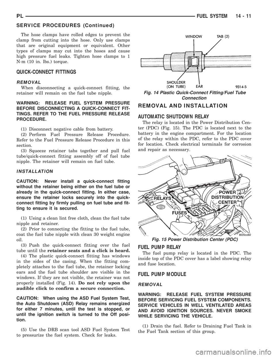
(4) The plastic quick-connect fitting has windows
in the sides of the casing. When the fitting com-
pletely attaches to the fuel tube, the retainer locking
ears and the fuel tube shoulder are visible in the
windows. If they are not visible, the retainer was not
properly installed (Fig. 14).Do not rely upon the
audible click to confirm a secure connection.
CAUTION: When using the ASD Fuel System Test,
the Auto Shutdown (ASD) Relay remains energized
for either 7 minutes, until the test is stopped, or
until the ignition switch is turned to the Off posi-
tion.
(5) Use the DRB scan tool ASD Fuel System Test
to pressurize the fuel system. Check for leaks.
REMOVAL AND INSTALLATION
AUTOMATIC SHUTDOWN RELAY
The relay is located in the Power Distribution Cen-
ter (PDC) (Fig. 15). The PDC is located next to the
battery in the engine compartment. For the location
of the relay within the PDC, refer to the PDC cover
for location. Check electrical terminals for corrosion
and repair as necessary.
FUEL PUMP RELAY
The fuel pump relay is located in the PDC. The
inside top of the PDC cover has a label showing relay
and fuse location.
FUEL PUMP MODULE
REMOVAL
WARNING: RELEASE FUEL SYSTEM PRESSURE
BEFORE SERVICING FUEL SYSTEM COMPONENTS.
SERVICE VEHICLES IN WELL VENTILATED AREAS
AND AVOID IGNITION SOURCES. NEVER SMOKE
WHILE SERVICING THE VEHICLE.
(1) Drain the fuel. Refer to Draining Fuel Tank in
the Fuel Tank section of this group.
Fig. 14 Plastic Quick-Connect Fitting/Fuel Tube
Connection
Fig. 15 Power Distribution Center (PDC)
PLFUEL SYSTEM 14 - 11
SERVICE PROCEDURES (Continued)
Page 1083 of 1200
BODY COMPONENTS
INDEX
page page
DIAGNOSIS AND TESTING
WATER LEAKS.......................... 3
WIND NOISE............................ 4
SERVICE PROCEDURES
HEAT STAKING.......................... 4
REMOVAL AND INSTALLATION
WINDOW REGULATORÐ4 DOOR........... 36
A-PILLAR TRIM.......................... 4
B-PILLAR APPLIQUEÐ2 DOOR.............. 5
B-PILLAR APPLIQUEÐ4 DOOR.............. 5
B-PILLAR TRIMÐ4 DOOR.................. 6
B-PILLAR WEATHERSTRIP CHANNEL......... 6
BODY VENT............................. 6
CARPET............................... 7
CHILD RESTRAINT SEAT BACK............. 8
CHILD SEAT MODULE..................... 8
COWL COVER........................... 7
DOOR HINGE........................... 9
DOOR LOCK CYLINDER.................. 10
DOOR OPENING TRIM WELT.............. 10
DOOR SILL TRIM........................ 10
DOOR................................. 9
FLOOR CONSOLE LATCH................. 11
FLOOR CONSOLE....................... 11
FRONT DOOR CHECK STOP............... 11
FRONT DOOR GLASSÐ2 DOOR............ 12
FRONT DOOR GLASSÐ4 DOOR............ 13
FRONT DOOR INNER BELT WEATHERSTRIP . . 13
FRONT DOOR LATCH STRIKER............ 14
FRONT DOOR LATCH.................... 13
FRONT DOOR OUTER BELT WEATHERSTRIP . 14
FRONT DOOR OUTSIDE HANDLE........... 14
FRONT DOOR TRIM PANEL................ 14
FRONT DOOR WATER SHIELD............. 16
FRONT DOOR WEATHERSTRIP............ 16
FRONT OUTBOARD SEAT BELT............ 17
FRONT SEAT BELT BUCKLE............... 18
FRONT SEAT BELT RETRACTOR........... 18
FRONT SEAT........................... 17
FRONT SHOULDER BELT ADJUSTER........ 18
FRONT VERTICAL GUIDE BAR............. 18
GRILLE............................... 19
HEADLINING........................... 19
HOOD HINGE.......................... 20
HOOD LATCH.......................... 21
HOOD RELEASE CABLE.................. 21
HOOD................................ 20
LOCK BUTTON BELL-CRANK.............. 21
LOWER QUARTER TRIMÐ4 DOOR.......... 22PARCEL SHELF TRIM.................... 22
QUARTER TRIM PANELÐ2 DOOR........... 22
REAR DOOR GLASS..................... 23
REAR DOOR INNER BELT WEATHERSTRIP . . . 23
REAR DOOR INTERLOCK LATCH STRIKER . . . 24
REAR DOOR LATCH STRIKER............. 24
REAR DOOR LATCH..................... 24
REAR DOOR LOCK BELL CRANK........... 24
REAR DOOR OUTER BELT WEATHERSTRIP . . 25
REAR DOOR TRIM....................... 25
REAR DOOR WINDOW REGULATOR........ 25
REAR SEAT BACK....................... 26
REAR SEAT BELT BUCKLE................ 26
REAR SEAT BELT RETRACTOR............ 26
REAR SEAT CUSHION.................... 26
REAR SPOILER......................... 27
REAR VERTICAL GUIDE BAR.............. 27
ROOF APERTURE (RAP) MOLDING.......... 28
ROOF RACK CROSS RAILS............... 28
ROOF RACK........................... 28
ROOF RAIL WEATHER-STRIP FOUR DOOR . . . 29
ROOF RAIL WEATHER-STRIP ± TWO DOOR . . . 29
SIDE COWL TRIM....................... 30
SIDE VIEW MIRROR STANCHION........... 31
SIDE VIEW MIRROR TRIM COVER.......... 31
SIDE VIEW MIRROR..................... 30
SUN VISOR SUPPORT................... 31
SUN VISOR............................ 31
TRUNK CARPET........................ 31
TRUNK LATCH STRIKER.................. 32
TRUNK LATCH.......................... 32
TRUNK LID LIFT SPRINGS................ 33
TRUNK LID............................ 32
TRUNK LOCK CYLINDER................. 33
TRUNK TRIM PANEL..................... 34
TRUNK WEATHERSTRIP.................. 34
UPPER QUARTER TRIMÐ4 DOOR.......... 34
WINDOW INNERBELT STABILIZER.......... 34
WINDOW REGULATORÐ2 DOOR........... 35
ADJUSTMENTS
FRONT DOOR GLASS ADJUSTMENT........ 37
FRONT DOOR LATCH ADJUSTMENT........ 38
REAR DOOR GLASS ADJUSTMENT......... 38
REAR DOOR LATCH ADJUSTMENT.......... 39
SPECIFICATIONS
BODY LUBRICATION SPECIFICATIONS....... 39
SPECIAL TOOLS
BODY................................. 40
23 - 2 BODYPL
Page 1084 of 1200
DIAGNOSIS AND TESTING
WATER LEAKS
Water leaks can be caused by poor sealing,
improper body component alignment, body seam
porosity, missing plugs, or blocked drain holes. Cen-
trifugal and gravitational force can cause water to
drip from a location away from the actual leak point,
making leak detection difficult. All body sealing
points should be water tight in normal wet-driving
conditions. Water flowing downward from the front of
the vehicle should not enter the passenger or luggage
compartment. Moving sealing surfaces will not
always seal water tight under all conditions. At
times, side glass or door seals will allow water to
enter the passenger compartment during high pres-
sure washing or hard driving rain (severe) condi-
tions. Overcompensating on door or glass
adjustments to stop a water leak that occurs under
severe conditions can cause premature seal wear and
excessive closing or latching effort. After completing
a repair, water-test vehicle to verify leak has stopped
before returning vehicle to use.
VISUAL INSPECTION BEFORE WATER LEAK
TESTS
Verify that floor and body plugs are in place, body
drains are clear, and body components are properly
aligned and sealed. If component alignment or seal-
ing is necessary, refer to the appropriate section of
this group for proper procedures.
WATER LEAK TESTS
WARNING: DO NOT USE ELECTRIC SHOP LIGHTS
OR TOOLS IN WATER TEST AREA. PERSONAL
INJURY CAN RESULT.
When the conditions causing a water leak have
been determined, simulate the conditions as closely
as possible.
²If a leak occurs with the vehicle parked in a
steady light rain, flood the leak area with an open-
ended garden hose.
²If a leak occurs while driving at highway speeds
in a steady rain, test the leak area with a reasonable
velocity stream or fan spray of water. Direct the
spray in a direction comparable to actual conditions.
²If a leak occurs when the vehicle is parked on an
incline, hoist the end or side of the vehicle to simu-
late this condition. This method can be used when
the leak occurs when the vehicle accelerates, stops or
turns. If the leak occurs on acceleration, hoist the
front of the vehicle. If the leak occurs when braking,
hoist the back of the vehicle. If the leak occurs on left
turns, hoist the left side of the vehicle. If the leak
occurs on right turns, hoist the right side of the vehi-cle. For hoisting recommendations refer to Group 0,
Lubrication and Maintenance, General Information
section.
WATER LEAK DETECTION
To detect a water leak point-of-entry, do a water
test and watch for water tracks or droplets forming
on the inside of the vehicle. If necessary, remove inte-
rior trim covers or panels to gain visual access to the
leak area. If the hose cannot be positioned without
being held, have someone help do the water test.
Some water leaks must be tested for a considerable
length of time to become apparent. When a leak
appears, find the highest point of the water track or
drop. The highest point usually will show the point of
entry. After leak point has been found, repair the
leak and water test to verify that the leak has
stopped.
Locating the entry point of water that is leaking
into a cavity between panels can be difficult. The
trapped water may splash or run from the cavity,
often at a distance from the entry point. Most water
leaks of this type become apparent after accelerating,
stopping, turning, or when on an incline.
MIRROR INSPECTION METHOD
When a leak point area is visually obstructed, use
a suitable mirror to gain visual access. A mirror can
also be used to deflect light to a limited-access area
to assist in locating a leak point.
BRIGHT LIGHT LEAK TEST METHOD
Some water leaks in the luggage compartment can
be detected without water testing. Position the vehi-
cle in a brightly lit area. From inside the darkened
luggage compartment inspect around seals and body
seams. If necessary, have a helper direct a drop light
over the suspected leak areas around the luggage
compartment. If light is visible through a normally
sealed location, water could enter through the open-
ing.
PRESSURIZED LEAK TEST METHOD
When a water leak into the passenger compart-
ment cannot be detected by water testing, pressurize
the passenger compartment and soap test exterior of
the vehicle. To pressurize the passenger compart-
ment, close all doors and windows, start engine, and
set heater control to high blower in HEAT position. If
engine can not be started, connect a charger to the
battery to ensure adequate voltage to the blower.
With interior pressurized, apply dish detergent solu-
tion to suspected leak area on the exterior of the
vehicle. Apply detergent solution with spray device or
soft bristle brush. If soap bubbles occur at a body
seam, joint, seal or gasket, the leak entry point could
be at that location.
PLBODY 23 - 3
Page 1093 of 1200
INSTALLATION
(1) Position door check on vehicle and install bolts
attaching stop to door end frame.
(2) Install door speaker, if so equipped.
(3) Install bolt holding door check stop to hinge
pillar.
(4) Install door trim panel and water shield.
FRONT DOOR GLASSÐ2 DOOR
REMOVAL
(1) Remove door trim panel and water shield.
(2) Remove inner and outer door belt weather-
strips.
(3) Loosen inner belt stabilizer.
(4) Lower door glass to bottom of travel to access
glass attachment bolts.
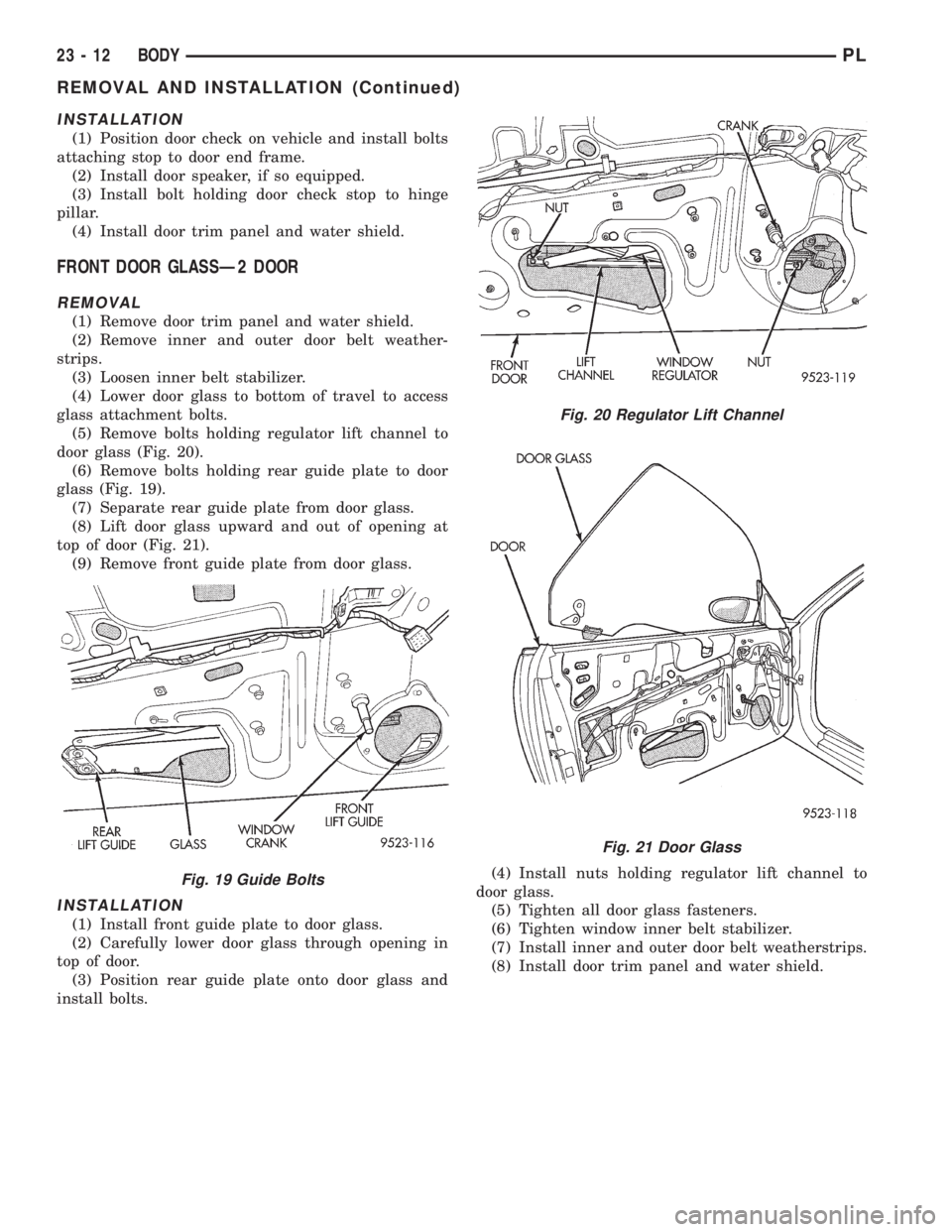
(5) Remove bolts holding regulator lift channel to
door glass (Fig. 20).
(6) Remove bolts holding rear guide plate to door
glass (Fig. 19).
(7) Separate rear guide plate from door glass.
(8) Lift door glass upward and out of opening at
top of door (Fig. 21).
(9) Remove front guide plate from door glass.
INSTALLATION
(1) Install front guide plate to door glass.
(2) Carefully lower door glass through opening in
top of door.
(3) Position rear guide plate onto door glass and
install bolts.(4) Install nuts holding regulator lift channel to
door glass.
(5) Tighten all door glass fasteners.
(6) Tighten window inner belt stabilizer.
(7) Install inner and outer door belt weatherstrips.
(8) Install door trim panel and water shield.
Fig. 19 Guide Bolts
Fig. 20 Regulator Lift Channel
Fig. 21 Door Glass
23 - 12 BODYPL
REMOVAL AND INSTALLATION (Continued)
Page 1094 of 1200
FRONT DOOR GLASSÐ4 DOOR
REMOVAL
(1) Remove door trim panel and water shield.
(2) Remove inner door belt weatherstrip.
(3) Loosen window inner belt stabilizer.
(4) Lower door glass to bottom of door to gain
access to attaching bolts.
(5) Remove bolts holding door glass to window reg-
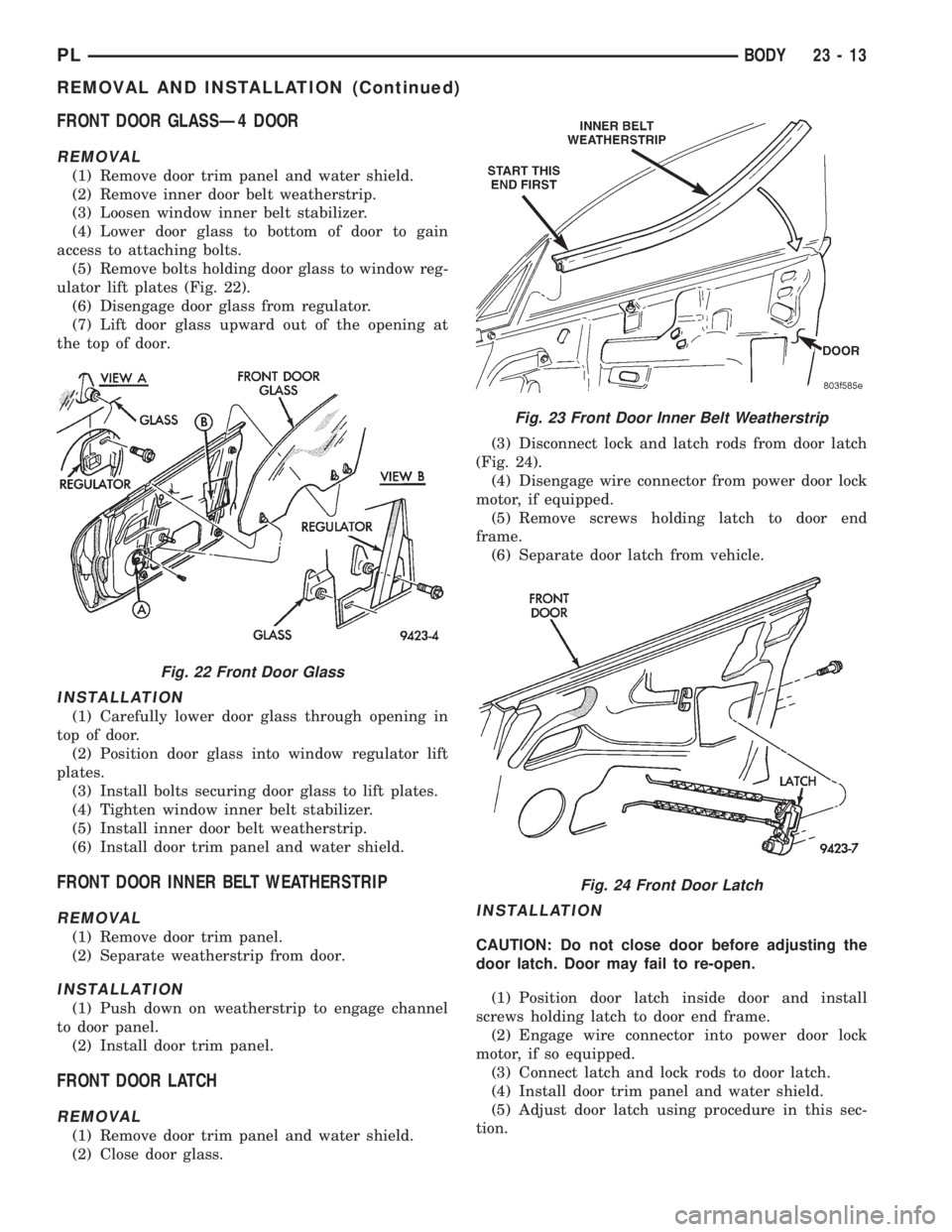
ulator lift plates (Fig. 22).
(6) Disengage door glass from regulator.
(7) Lift door glass upward out of the opening at
the top of door.
INSTALLATION
(1) Carefully lower door glass through opening in
top of door.
(2) Position door glass into window regulator lift
plates.
(3) Install bolts securing door glass to lift plates.
(4) Tighten window inner belt stabilizer.
(5) Install inner door belt weatherstrip.
(6) Install door trim panel and water shield.
FRONT DOOR INNER BELT WEATHERSTRIP
REMOVAL
(1) Remove door trim panel.
(2) Separate weatherstrip from door.
INSTALLATION
(1) Push down on weatherstrip to engage channel
to door panel.
(2) Install door trim panel.
FRONT DOOR LATCH
REMOVAL
(1) Remove door trim panel and water shield.
(2) Close door glass.(3) Disconnect lock and latch rods from door latch
(Fig. 24).
(4) Disengage wire connector from power door lock
motor, if equipped.
(5) Remove screws holding latch to door end
frame.
(6) Separate door latch from vehicle.
INSTALLATION
CAUTION: Do not close door before adjusting the
door latch. Door may fail to re-open.
(1) Position door latch inside door and install
screws holding latch to door end frame.
(2) Engage wire connector into power door lock
motor, if so equipped.
(3) Connect latch and lock rods to door latch.
(4) Install door trim panel and water shield.
(5) Adjust door latch using procedure in this sec-
tion.
Fig. 22 Front Door Glass
Fig. 23 Front Door Inner Belt Weatherstrip
Fig. 24 Front Door Latch
PLBODY 23 - 13
REMOVAL AND INSTALLATION (Continued)