high beam DODGE NEON 1999 Service Repair Manual
[x] Cancel search | Manufacturer: DODGE, Model Year: 1999, Model line: NEON, Model: DODGE NEON 1999Pages: 1200, PDF Size: 35.29 MB
Page 237 of 1200
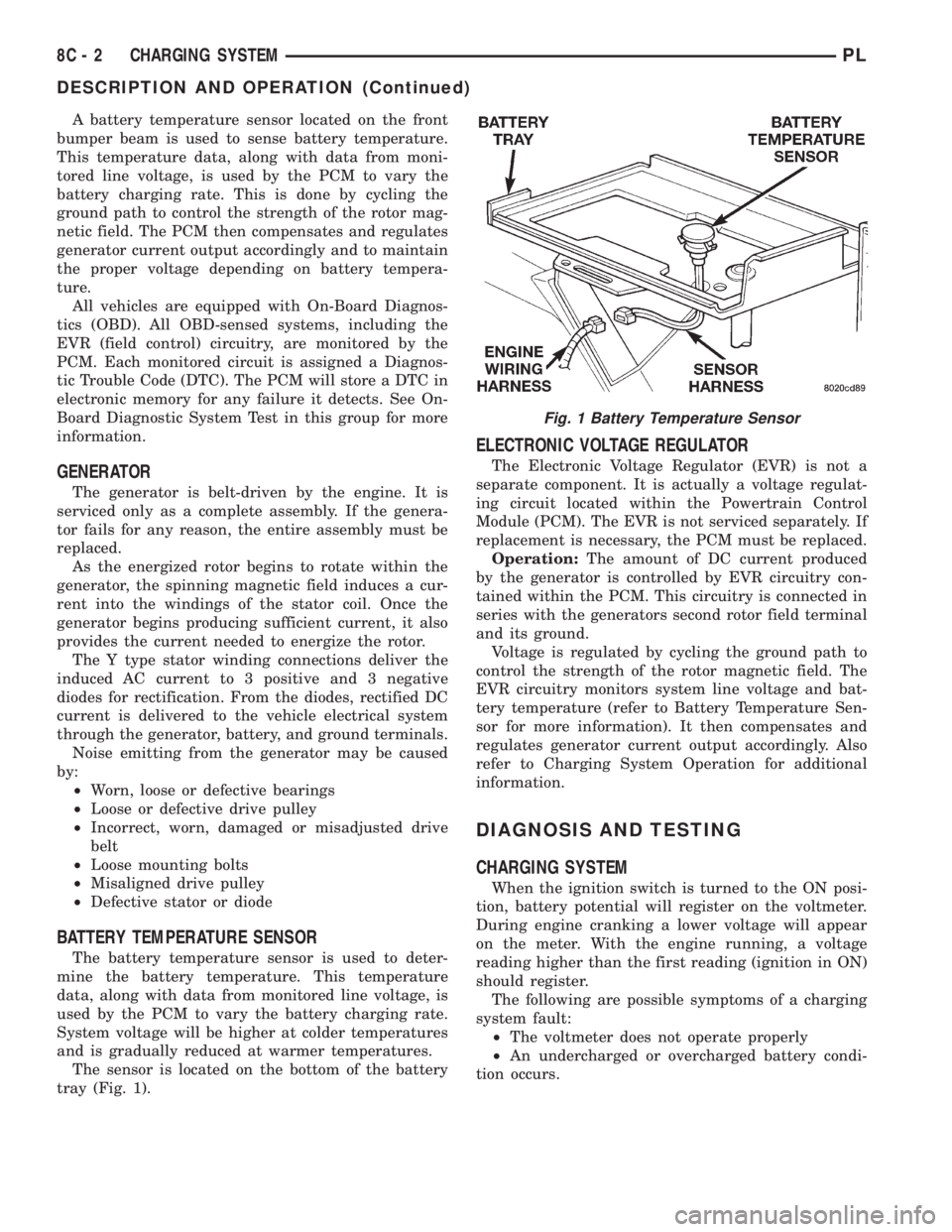
A battery temperature sensor located on the front
bumper beam is used to sense battery temperature.
This temperature data, along with data from moni-
tored line voltage, is used by the PCM to vary the
battery charging rate. This is done by cycling the
ground path to control the strength of the rotor mag-
netic field. The PCM then compensates and regulates
generator current output accordingly and to maintain
the proper voltage depending on battery tempera-
ture.
All vehicles are equipped with On-Board Diagnos-
tics (OBD). All OBD-sensed systems, including the
EVR (field control) circuitry, are monitored by the
PCM. Each monitored circuit is assigned a Diagnos-
tic Trouble Code (DTC). The PCM will store a DTC in
electronic memory for any failure it detects. See On-
Board Diagnostic System Test in this group for more
information.
GENERATOR
The generator is belt-driven by the engine. It is
serviced only as a complete assembly. If the genera-
tor fails for any reason, the entire assembly must be
replaced.
As the energized rotor begins to rotate within the
generator, the spinning magnetic field induces a cur-
rent into the windings of the stator coil. Once the
generator begins producing sufficient current, it also
provides the current needed to energize the rotor.
The Y type stator winding connections deliver the
induced AC current to 3 positive and 3 negative
diodes for rectification. From the diodes, rectified DC
current is delivered to the vehicle electrical system
through the generator, battery, and ground terminals.
Noise emitting from the generator may be caused
by:
²Worn, loose or defective bearings
²Loose or defective drive pulley
²Incorrect, worn, damaged or misadjusted drive
belt
²Loose mounting bolts
²Misaligned drive pulley
²Defective stator or diode
BATTERY TEMPERATURE SENSOR
The battery temperature sensor is used to deter-
mine the battery temperature. This temperature
data, along with data from monitored line voltage, is
used by the PCM to vary the battery charging rate.
System voltage will be higher at colder temperatures
and is gradually reduced at warmer temperatures.
The sensor is located on the bottom of the battery
tray (Fig. 1).
ELECTRONIC VOLTAGE REGULATOR
The Electronic Voltage Regulator (EVR) is not a
separate component. It is actually a voltage regulat-
ing circuit located within the Powertrain Control
Module (PCM). The EVR is not serviced separately. If
replacement is necessary, the PCM must be replaced.
Operation:The amount of DC current produced
by the generator is controlled by EVR circuitry con-
tained within the PCM. This circuitry is connected in
series with the generators second rotor field terminal
and its ground.
Voltage is regulated by cycling the ground path to
control the strength of the rotor magnetic field. The
EVR circuitry monitors system line voltage and bat-
tery temperature (refer to Battery Temperature Sen-
sor for more information). It then compensates and
regulates generator current output accordingly. Also
refer to Charging System Operation for additional
information.
DIAGNOSIS AND TESTING
CHARGING SYSTEM
When the ignition switch is turned to the ON posi-
tion, battery potential will register on the voltmeter.
During engine cranking a lower voltage will appear
on the meter. With the engine running, a voltage
reading higher than the first reading (ignition in ON)
should register.
The following are possible symptoms of a charging
system fault:
²The voltmeter does not operate properly
²An undercharged or overcharged battery condi-
tion occurs.
Fig. 1 Battery Temperature Sensor
8C - 2 CHARGING SYSTEMPL
DESCRIPTION AND OPERATION (Continued)
Page 242 of 1200
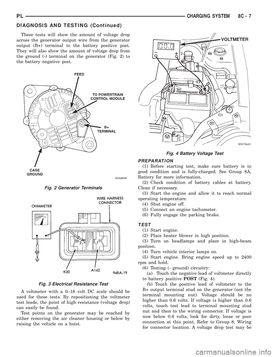
These tests will show the amount of voltage drop
across the generator output wire from the generator
output (B+) terminal to the battery positive post.
They will also show the amount of voltage drop from
the ground (-) terminal on the generator (Fig. 2) to
the battery negative post.
A voltmeter with a 0±18 volt DC scale should be
used for these tests. By repositioning the voltmeter
test leads, the point of high resistance (voltage drop)
can easily be found.
Test points on the generator may be reached by
either removing the air cleaner housing or below by
raising the vehicle on a hoist.
PREPARATION
(1) Before starting test, make sure battery is in
good condition and is fully-charged. See Group 8A,
Battery for more information.
(2) Check condition of battery cables at battery.
Clean if necessary.
(3) Start the engine and allow it to reach normal
operating temperature.
(4) Shut engine off.
(5) Connect an engine tachometer.
(6) Fully engage the parking brake.
TEST
(1) Start engine.
(2) Place heater blower in high position.
(3) Turn on headlamps and place in high-beam
position.
(4) Turn vehicle interior lamps on.
(5) Start engine. Bring engine speed up to 2400
rpm and hold.
(6) Testing (- ground) circuitry:
(a) Touch the negative lead of voltmeter directly
to battery positivePOST(Fig. 4).
(b) Touch the positive lead of voltmeter to the
B+ output terminal stud on the generator (not the
terminal mounting nut). Voltage should be no
higher than 0.6 volts. If voltage is higher than 0.6
volts, touch test lead to terminal mounting stud
nut and then to the wiring connector. If voltage is
now below 0.6 volts, look for dirty, loose or poor
connection at this point. Refer to Group 8, Wiring
for connector location. A voltage drop test may be
Fig. 2 Generator Terminals
Fig. 3 Electrical Resistance Test
Fig. 4 Battery Voltage Test
PLCHARGING SYSTEM 8C - 7
DIAGNOSIS AND TESTING (Continued)
Page 271 of 1200
When the ignition switch is in the OFF position, or
when the radio frequency is being displayed, time
keeping is accurately maintained.
The procedure for setting the clock varies slightly
with each radio. The correct procedure is described in
the individual radio operating instructions. Refer to
the Owner's Manual supplied with the vehicle.
INSTRUMENT CLUSTER
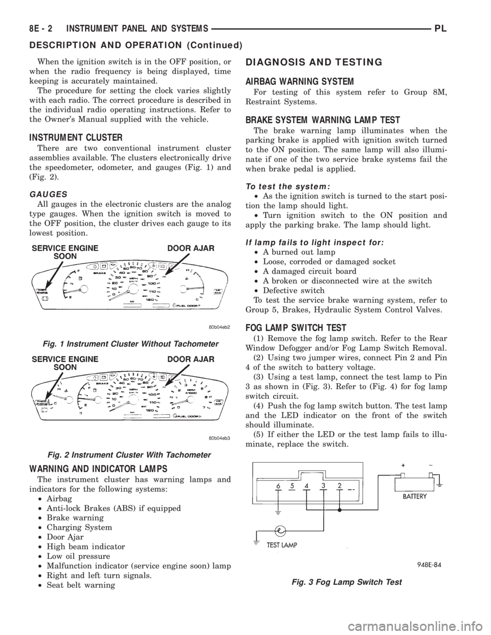
There are two conventional instrument cluster
assemblies available. The clusters electronically drive
the speedometer, odometer, and gauges (Fig. 1) and
(Fig. 2).
GAUGES
All gauges in the electronic clusters are the analog
type gauges. When the ignition switch is moved to
the OFF position, the cluster drives each gauge to its
lowest position.
WARNING AND INDICATOR LAMPS
The instrument cluster has warning lamps and
indicators for the following systems:
²Airbag
²Anti-lock Brakes (ABS) if equipped
²Brake warning
²Charging System
²Door Ajar
²High beam indicator
²Low oil pressure
²Malfunction indicator (service engine soon) lamp
²Right and left turn signals.
²Seat belt warning
DIAGNOSIS AND TESTING
AIRBAG WARNING SYSTEM
For testing of this system refer to Group 8M,
Restraint Systems.
BRAKE SYSTEM WARNING LAMP TEST
The brake warning lamp illuminates when the
parking brake is applied with ignition switch turned
to the ON position. The same lamp will also illumi-
nate if one of the two service brake systems fail the
when brake pedal is applied.
To test the system:
²As the ignition switch is turned to the start posi-
tion the lamp should light.
²Turn ignition switch to the ON position and
apply the parking brake. The lamp should light.
If lamp fails to light inspect for:
²A burned out lamp
²Loose, corroded or damaged socket
²A damaged circuit board
²A broken or disconnected wire at the switch
²Defective switch
To test the service brake warning system, refer to
Group 5, Brakes, Hydraulic System Control Valves.
FOG LAMP SWITCH TEST
(1) Remove the fog lamp switch. Refer to the Rear
Window Defogger and/or Fog Lamp Switch Removal.
(2) Using two jumper wires, connect Pin 2 and Pin
4 of the switch to battery voltage.
(3) Using a test lamp, connect the test lamp to Pin
3 as shown in (Fig. 3). Refer to (Fig. 4) for fog lamp
switch circuit.
(4) Push the fog lamp switch button. The test lamp
and the LED indicator on the front of the switch
should illuminate.
(5) If either the LED or the test lamp fails to illu-
minate, replace the switch.Fig. 1 Instrument Cluster Without Tachometer
Fig. 2 Instrument Cluster With Tachometer
Fig. 3 Fog Lamp Switch Test
8E - 2 INSTRUMENT PANEL AND SYSTEMSPL
DESCRIPTION AND OPERATION (Continued)
Page 290 of 1200
ANTENNA
The antenna has a short cable which connects into
the instrument panel harness. The connection is
made on the right side of the instrument panel.
Antenna performance may be tested by substitut-
ing a known good antenna. It is also possible to
check short or open circuits with an ohmmeter or
continuity light once the antenna cable is discon-
nected from the radio as follows:
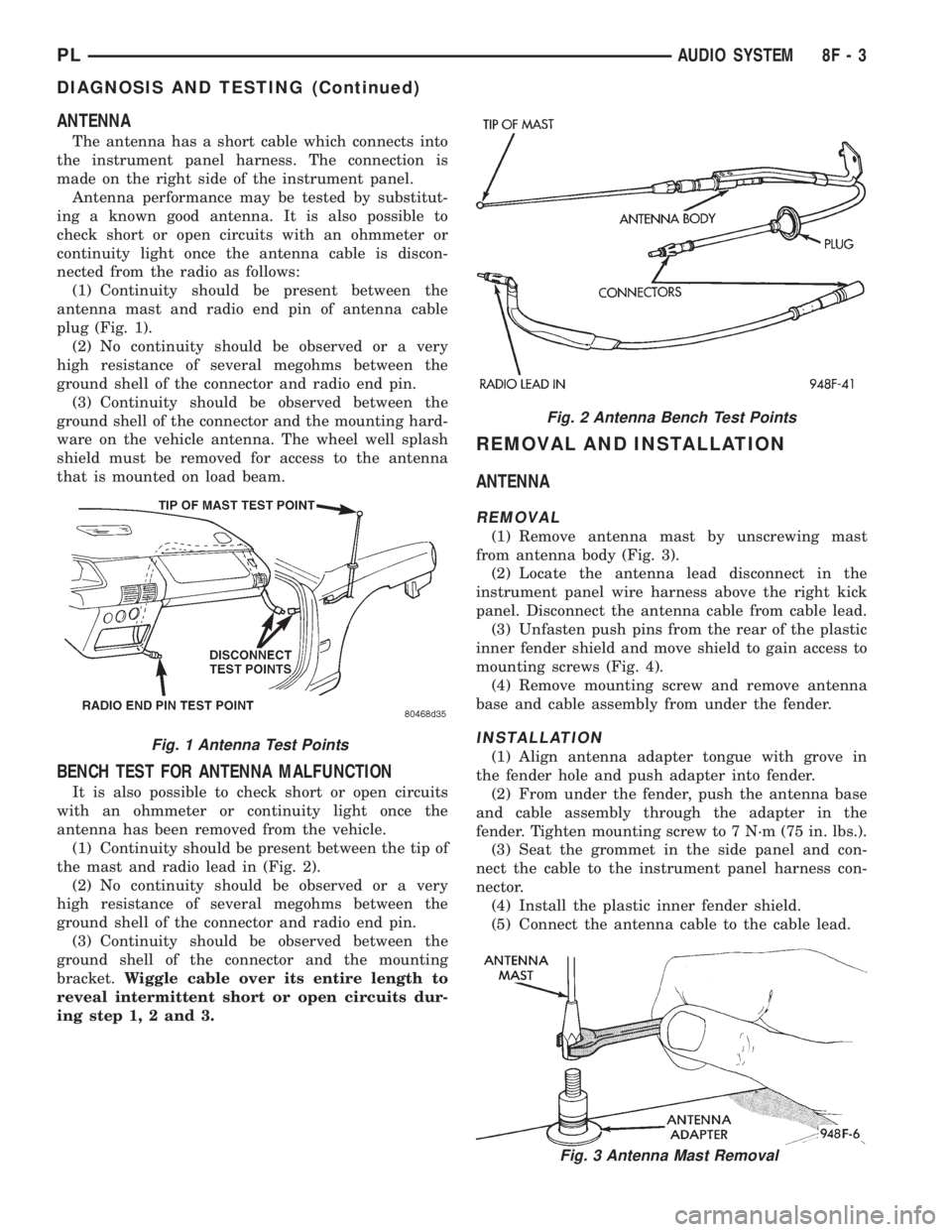
(1) Continuity should be present between the
antenna mast and radio end pin of antenna cable
plug (Fig. 1).
(2) No continuity should be observed or a very
high resistance of several megohms between the
ground shell of the connector and radio end pin.
(3) Continuity should be observed between the
ground shell of the connector and the mounting hard-
ware on the vehicle antenna. The wheel well splash
shield must be removed for access to the antenna
that is mounted on load beam.
BENCH TEST FOR ANTENNA MALFUNCTION
It is also possible to check short or open circuits
with an ohmmeter or continuity light once the
antenna has been removed from the vehicle.
(1) Continuity should be present between the tip of
the mast and radio lead in (Fig. 2).
(2) No continuity should be observed or a very
high resistance of several megohms between the
ground shell of the connector and radio end pin.
(3) Continuity should be observed between the
ground shell of the connector and the mounting
bracket.Wiggle cable over its entire length to
reveal intermittent short or open circuits dur-
ing step 1, 2 and 3.
REMOVAL AND INSTALLATION
ANTENNA
REMOVAL
(1) Remove antenna mast by unscrewing mast
from antenna body (Fig. 3).
(2) Locate the antenna lead disconnect in the
instrument panel wire harness above the right kick
panel. Disconnect the antenna cable from cable lead.
(3) Unfasten push pins from the rear of the plastic
inner fender shield and move shield to gain access to
mounting screws (Fig. 4).
(4) Remove mounting screw and remove antenna
base and cable assembly from under the fender.
INSTALLATION
(1) Align antenna adapter tongue with grove in
the fender hole and push adapter into fender.
(2) From under the fender, push the antenna base
and cable assembly through the adapter in the
fender. Tighten mounting screw to 7 N´m (75 in. lbs.).
(3) Seat the grommet in the side panel and con-
nect the cable to the instrument panel harness con-
nector.
(4) Install the plastic inner fender shield.
(5) Connect the antenna cable to the cable lead.
Fig. 2 Antenna Bench Test Points
Fig. 3 Antenna Mast Removal
Fig. 1 Antenna Test Points
PLAUDIO SYSTEM 8F - 3
DIAGNOSIS AND TESTING (Continued)
Page 330 of 1200
LAMPS
CONTENTS
page page
BULB APPLICATION...................... 13
HEADLAMP ALIGNMENT................... 4
LAMP BULB SERVICE..................... 6LAMP DIAGNOSIS........................ 1
LAMP SERVICE........................... 9
LAMP SYSTEMS......................... 12
LAMP DIAGNOSIS
INDEX
page page
GENERAL INFORMATION
DAYTIME RUNNING LAMP MODULE.......... 1
GENERAL INFORMATION.................. 1
SAFETY PRECAUTIONS................... 1DIAGNOSIS AND TESTING
DIAGNOSTIC PROCEDURES................ 1
FOG LAMP.............................. 3
HEADLAMP DIAGNOSIS................... 2
GENERAL INFORMATION
GENERAL INFORMATION
Each vehicle is equipped with various lamp assem-
blies. A good ground is necessary for proper lighting
operation. Grounding is provided by the lamp socket
when it comes in contact with the metal body, or
through a separate ground wire.
When changing lamp bulbs check the socket for
corrosion. If corrosion is present, clean it with a wire
brush and coat the inside of the socket lightly with
Mopar Multi-Purpose Grease or equivalent.
SAFETY PRECAUTIONS
WARNING: EYE PROTECTION SHOULD BE USED
WHEN SERVICING GLASS COMPONENTS. PER-
SONAL INJURY CAN RESULT.
CAUTION: Do not touch the glass of halogen bulbs
with fingers or other possibly oily surface, reduced
bulb life will result.
Do not use bulbs with higher candle power than
indicated in the Bulb Application table at the end of
this group. Damage to lamp and/or Daytime Run-
ning Lamp Module can result.
Do not use fuses, circuit breakers or relays hav-
ing greater amperage value than indicated on the
fuse panel or in the Owners Manual.When it is necessary to remove components to ser-
vice another, it should not be necessary to apply
excessive force or bend a component to remove it.
Before damaging a trim component, verify hidden
fasteners or captured edges are not holding the com-
ponent in place.
DAYTIME RUNNING LAMP MODULE
PL vehicles built for use in Canada are equipped
with a Daytime Running Lamp (DRL) system. The
DRL system operates the headlamps at 50% illumi-
nation with the headlamp switch OFF, park brake
released and the ignition ON. The DRL system is
controlled by the Daytime Running Lamp Module.
The DRL module overrides the headlamp switch
when the headlamps are turned OFF. The headlamps
operate normally when the headlamps are turned
ON.
DIAGNOSIS AND TESTING
DIAGNOSTIC PROCEDURES
When a vehicle experiences problems with the
headlamp system, verify the condition of the battery
connections, charging system, headlamp bulbs, wire
connectors, relay, high beam dimmer switch and
headlamp switch. Refer to Group 8W, Wiring Dia-
grams for component locations and circuit informa-
tion.
PLLAMPS 8L - 1
Page 333 of 1200
HEADLAMP ALIGNMENT
INDEX
page page
GENERAL INFORMATION
HEADLAMP ALIGNMENT................... 4
SERVICE PROCEDURES
HEADLAMP ALIGNMENT PREPARATION....... 4ADJUSTMENTS
FOG LAMP ALIGNMENT................... 4
HEADLAMP ADJUSTMENT USING ALIGNMENT
SCREEN.............................. 4
GENERAL INFORMATION
HEADLAMP ALIGNMENT
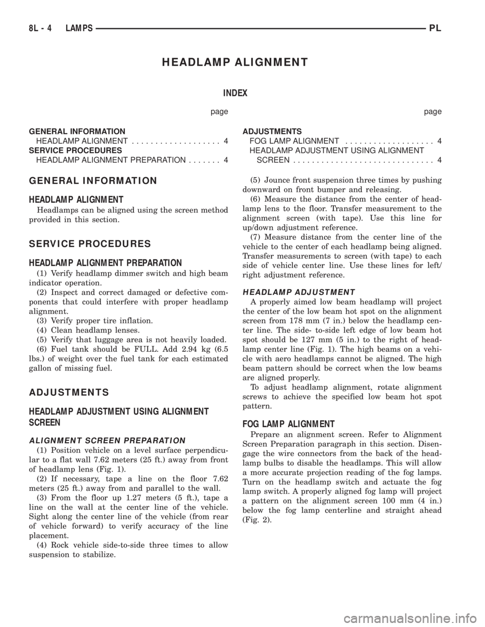
Headlamps can be aligned using the screen method
provided in this section.
SERVICE PROCEDURES
HEADLAMP ALIGNMENT PREPARATION
(1) Verify headlamp dimmer switch and high beam
indicator operation.
(2) Inspect and correct damaged or defective com-
ponents that could interfere with proper headlamp
alignment.
(3) Verify proper tire inflation.
(4) Clean headlamp lenses.
(5) Verify that luggage area is not heavily loaded.
(6) Fuel tank should be FULL. Add 2.94 kg (6.5
lbs.) of weight over the fuel tank for each estimated
gallon of missing fuel.
ADJUSTMENTS
HEADLAMP ADJUSTMENT USING ALIGNMENT
SCREEN
ALIGNMENT SCREEN PREPARATION
(1) Position vehicle on a level surface perpendicu-
lar to a flat wall 7.62 meters (25 ft.) away from front
of headlamp lens (Fig. 1).
(2) If necessary, tape a line on the floor 7.62
meters (25 ft.) away from and parallel to the wall.
(3) From the floor up 1.27 meters (5 ft.), tape a
line on the wall at the center line of the vehicle.
Sight along the center line of the vehicle (from rear
of vehicle forward) to verify accuracy of the line
placement.
(4) Rock vehicle side-to-side three times to allow
suspension to stabilize.(5) Jounce front suspension three times by pushing
downward on front bumper and releasing.
(6) Measure the distance from the center of head-
lamp lens to the floor. Transfer measurement to the
alignment screen (with tape). Use this line for
up/down adjustment reference.
(7) Measure distance from the center line of the
vehicle to the center of each headlamp being aligned.
Transfer measurements to screen (with tape) to each
side of vehicle center line. Use these lines for left/
right adjustment reference.
HEADLAMP ADJUSTMENT
A properly aimed low beam headlamp will project
the center of the low beam hot spot on the alignment
screen from 178 mm (7 in.) below the headlamp cen-
ter line. The side- to-side left edge of low beam hot
spot should be 127 mm (5 in.) to the right of head-
lamp center line (Fig. 1). The high beams on a vehi-
cle with aero headlamps cannot be aligned. The high
beam pattern should be correct when the low beams
are aligned properly.
To adjust headlamp alignment, rotate alignment
screws to achieve the specified low beam hot spot
pattern.
FOG LAMP ALIGNMENT
Prepare an alignment screen. Refer to Alignment
Screen Preparation paragraph in this section. Disen-
gage the wire connectors from the back of the head-
lamp bulbs to disable the headlamps. This will allow
a more accurate projection reading of the fog lamps.
Turn on the headlamp switch and actuate the fog
lamp switch. A properly aligned fog lamp will project
a pattern on the alignment screen 100 mm (4 in.)
below the fog lamp centerline and straight ahead
(Fig. 2).
8L - 4 LAMPSPL
Page 351 of 1200
BULB APPLICATION
INDEX
page page
GENERAL INFORMATION
INTRODUCTION......................... 8
SPECIFICATIONS
EXTERIOR LAMPS........................ 8INTERIOR LAMPS........................ 8
GENERAL INFORMATION
INTRODUCTION
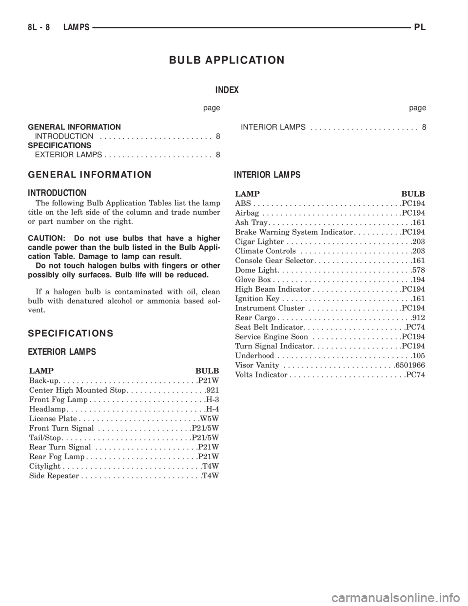
The following Bulb Application Tables list the lamp
title on the left side of the column and trade number
or part number on the right.
CAUTION: Do not use bulbs that have a higher
candle power than the bulb listed in the Bulb Appli-
cation Table. Damage to lamp can result.
Do not touch halogen bulbs with fingers or other
possibly oily surfaces. Bulb life will be reduced.
If a halogen bulb is contaminated with oil, clean
bulb with denatured alcohol or ammonia based sol-
vent.
SPECIFICATIONS
EXTERIOR LAMPS
LAMP BULB
Back-up...............................P21W
Center High Mounted Stop..................921
Front Fog Lamp..........................H-3
Headlamp...............................H-4
License Plate...........................W5W
Front Turn Signal.....................P21/5W
Tail/Stop.............................P21/5W
Rear Turn Signal.......................P21W
Rear Fog Lamp.........................P21W
Citylight...............................T4W
Side Repeater...........................T4W
INTERIOR LAMPS
LAMP BULB
ABS.................................PC194
Airbag...............................PC194
AshTray................................161
Brake Warning System Indicator...........PC194
Cigar Lighter............................203
Climate Controls.........................203
Console Gear Selector......................161
Dome Light..............................578
Glove Box...............................194
High Beam Indicator....................PC194
Ignition Key.............................161
Instrument Cluster.....................PC194
Rear Cargo..............................912
Seat Belt Indicator.......................PC74
Service Engine Soon....................PC194
Turn Signal Indicator....................PC194
Underhood..............................105
Visor Vanity.........................6501966
Volts Indicator..........................PC74
8L - 8 LAMPSPL
Page 494 of 1200
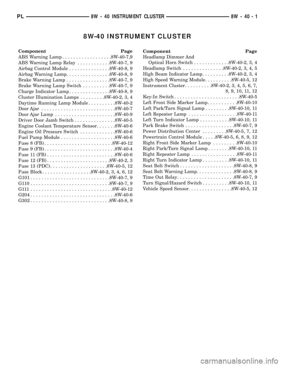
8W-40 INSTRUMENT CLUSTER
Component Page
ABS Warning Lamp..................8W-40-7,9
ABS Warning Lamp Relay............8W-40-7, 9
Airbag Control Module...............8W-40-8, 9
Airbag Warning Lamp................8W-40-8, 9
Brake Warning Lamp................8W-40-7, 9
Brake Warning Lamp Switch..........8W-40-7, 9
Charge Indicator Lamp...............8W-40-8, 9
Cluster Illumination Lamps.........8W-40-2, 3, 4
Daytime Running Lamp Module..........8W-40-2
Door Ajar...........................8W-40-7
Door Ajar Lamp......................8W-40-9
Driver Door Jamb Switch...............8W-40-5
Engine Coolant Temperature Sensor.......8W-40-6
Engine Oil Pressure Switch.............8W-40-6
Fuel Pump Module....................8W-40-6
Fuse 8 (FB).........................8W-40-12
Fuse 9 (FB)..........................8W-40-4
Fuse 11 (FB).........................8W-40-6
Fuse 12 (FB).......................8W-40-2, 3
Fuse 13 (PDC).....................8W-40-5, 12
Fuse Block..................8W-40-2, 3, 4, 6, 12
G101.............................8W-40-7, 9
G110.............................8W-40-7, 9
G111..............................8W-40-12
G204...............................8W-40-6
G302.............................8W-40-8, 9Component Page
Headlamp Dimmer And
Optical Horn Switch.............8W-40-2, 3, 4
Headlamp Switch...............8W-40-2, 3, 4, 5
High Beam Indicator Lamp..........8W-40-2, 3, 4
High Speed Warning Module..........8W-40-5, 12
Instrument Cluster..........8W-40-2, 3, 4, 5, 6, 7,
8, 9, 10, 11, 12
Key-In Switch........................8W-40-5
Left Front Side Marker Lamp...........8W-40-10
Left Park/Turn Signal Lamp.........8W-40-10, 11
Left Repeater Lamp..................8W-40-11
Left Turn Indicator Lamp...........8W-40-10, 11
Park Brake Switch..................8W-40-7, 9
Power Distribution Center.........8W-40-5, 7, 12
Powertrain Control Module.....8W-40-5, 6, 8, 9, 12
Right Front Side Marker Lamp.........8W-40-10
Right Park/Turn Signal Lamp........8W-40-10, 11
Right Repeater Lamp.................8W-40-11
Right Turn Indicator Lamp..........8W-40-10, 11
Seat Belt Switch....................8W-40-8, 9
Seat Belt Warning Lamp..............8W-40-8, 9
Time Out Relay.....................8W-40-7, 9
Turn Signal/Hazard Switch..........8W-40-10, 11
Vehicle Speed Sensor................8W-40-5, 12
PL8W - 40 INSTRUMENT CLUSTER 8W - 40 - 1
Page 495 of 1200

12FUSE4A
12
32BLOCK FUSE
SWITCH
HEADLAMP
1
E1
20
TN
E2
20
OR
E2
22
OR
S210
C2
92C1
43
S209SWITCH HORN
OPTICAL
AND
DIMMER
HEADLAMP
MODULE LAMP
RUNNING
DAYTIME
HIGH
BEAM
INDICATOR
DRIVER
CLUSTER INSTRUMENT
BATT F33
L3
14
RD/OR
G34
16
RD/GYL3
16
RD/OR
2
1 0
CLUSTER
ILLUMINATION
LAMPSHIGH
BEAM
INDICATOR
LAMP OTHER RKE
0 OFF
1 PARK
2 HEAD
DRIVER INDICATORBEAMHIGH
(8W-11-17)(8W-11-2)
(8W-11-17)(8W-50-2)(8W-50-2) (8W-50-14) (8W-11-7)
(8W-50-2)
8W - 40 - 2 8W-40 INSTRUMENT CLUSTER
EXCEPT BUILT-UP-EXPORTPL
J988W-18270
Page 496 of 1200

12FUSE4A
12
32BLOCK FUSE
1
E1
20
TN
E2
20
OR
E2
22
OR
S210
C2
92C1
3
S209
CLUSTER INSTRUMENT
BATT F33
L3
14
RD/OR
L3
16
RD/OR
2
1 0
CLUSTER
ILLUMINATION
LAMPSHIGH
BEAM
INDICATOR
LAMP
SWITCH HORN
OPTICAL
AND
DIMMER
HEADLAMP
SWITCH
HEADLAMP0 OFF
1 PARK
2 HEAD
HIGH
BEAM
INDICATOR
DRIVER
(8W-11-18)(8W-11-3)
(8W-11-18)(8W-50-6) (8W-11-8)
(8W-50-3) (8W-50-3)
PL8W-40 INSTRUMENT CLUSTER
LHD BUILT-UP-EXPORT8W - 40 - 3
8271J988W-1