DODGE NEON 2000 Service Repair Manual
Manufacturer: DODGE, Model Year: 2000, Model line: NEON, Model: DODGE NEON 2000Pages: 1285, PDF Size: 29.42 MB
Page 301 of 1285
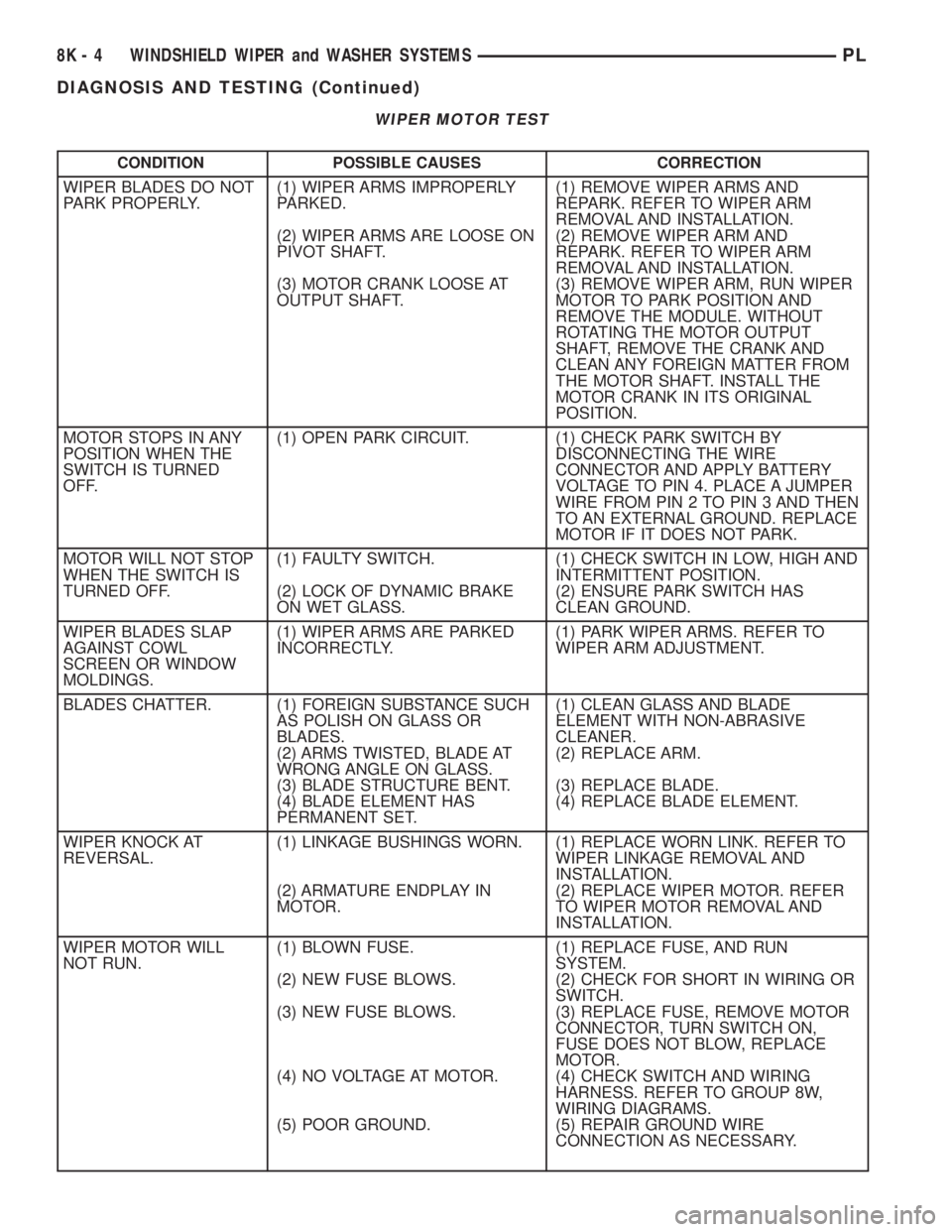
WIPER MOTOR TEST
CONDITION POSSIBLE CAUSES CORRECTION
WIPER BLADES DO NOT
PARK PROPERLY.(1) WIPER ARMS IMPROPERLY
PARKED.
(2) WIPER ARMS ARE LOOSE ON
PIVOT SHAFT.
(3) MOTOR CRANK LOOSE AT
OUTPUT SHAFT.(1) REMOVE WIPER ARMS AND
REPARK. REFER TO WIPER ARM
REMOVAL AND INSTALLATION.
(2) REMOVE WIPER ARM AND
REPARK. REFER TO WIPER ARM
REMOVAL AND INSTALLATION.
(3) REMOVE WIPER ARM, RUN WIPER
MOTOR TO PARK POSITION AND
REMOVE THE MODULE. WITHOUT
ROTATING THE MOTOR OUTPUT
SHAFT, REMOVE THE CRANK AND
CLEAN ANY FOREIGN MATTER FROM
THE MOTOR SHAFT. INSTALL THE
MOTOR CRANK IN ITS ORIGINAL
POSITION.
MOTOR STOPS IN ANY
POSITION WHEN THE
SWITCH IS TURNED
OFF.(1) OPEN PARK CIRCUIT. (1) CHECK PARK SWITCH BY
DISCONNECTING THE WIRE
CONNECTOR AND APPLY BATTERY
VOLTAGE TO PIN 4. PLACE A JUMPER
WIRE FROM PIN 2 TO PIN 3 AND THEN
TO AN EXTERNAL GROUND. REPLACE
MOTOR IF IT DOES NOT PARK.
MOTOR WILL NOT STOP
WHEN THE SWITCH IS
TURNED OFF.(1) FAULTY SWITCH.
(2) LOCK OF DYNAMIC BRAKE
ON WET GLASS.(1) CHECK SWITCH IN LOW, HIGH AND
INTERMITTENT POSITION.
(2) ENSURE PARK SWITCH HAS
CLEAN GROUND.
WIPER BLADES SLAP
AGAINST COWL
SCREEN OR WINDOW
MOLDINGS.(1) WIPER ARMS ARE PARKED
INCORRECTLY.(1) PARK WIPER ARMS. REFER TO
WIPER ARM ADJUSTMENT.
BLADES CHATTER. (1) FOREIGN SUBSTANCE SUCH
AS POLISH ON GLASS OR
BLADES.
(2) ARMS TWISTED, BLADE AT
WRONG ANGLE ON GLASS.
(3) BLADE STRUCTURE BENT.
(4) BLADE ELEMENT HAS
PERMANENT SET.(1) CLEAN GLASS AND BLADE
ELEMENT WITH NON-ABRASIVE
CLEANER.
(2) REPLACE ARM.
(3) REPLACE BLADE.
(4) REPLACE BLADE ELEMENT.
WIPER KNOCK AT
REVERSAL.(1) LINKAGE BUSHINGS WORN.
(2) ARMATURE ENDPLAY IN
MOTOR.(1) REPLACE WORN LINK. REFER TO
WIPER LINKAGE REMOVAL AND
INSTALLATION.
(2) REPLACE WIPER MOTOR. REFER
TO WIPER MOTOR REMOVAL AND
INSTALLATION.
WIPER MOTOR WILL
NOT RUN.(1) BLOWN FUSE.
(2) NEW FUSE BLOWS.
(3) NEW FUSE BLOWS.
(4) NO VOLTAGE AT MOTOR.
(5) POOR GROUND.(1) REPLACE FUSE, AND RUN
SYSTEM.
(2) CHECK FOR SHORT IN WIRING OR
SWITCH.
(3) REPLACE FUSE, REMOVE MOTOR
CONNECTOR, TURN SWITCH ON,
FUSE DOES NOT BLOW, REPLACE
MOTOR.
(4) CHECK SWITCH AND WIRING
HARNESS. REFER TO GROUP 8W,
WIRING DIAGRAMS.
(5) REPAIR GROUND WIRE
CONNECTION AS NECESSARY.
8K - 4 WINDSHIELD WIPER and WASHER SYSTEMSPL
DIAGNOSIS AND TESTING (Continued)
Page 302 of 1285
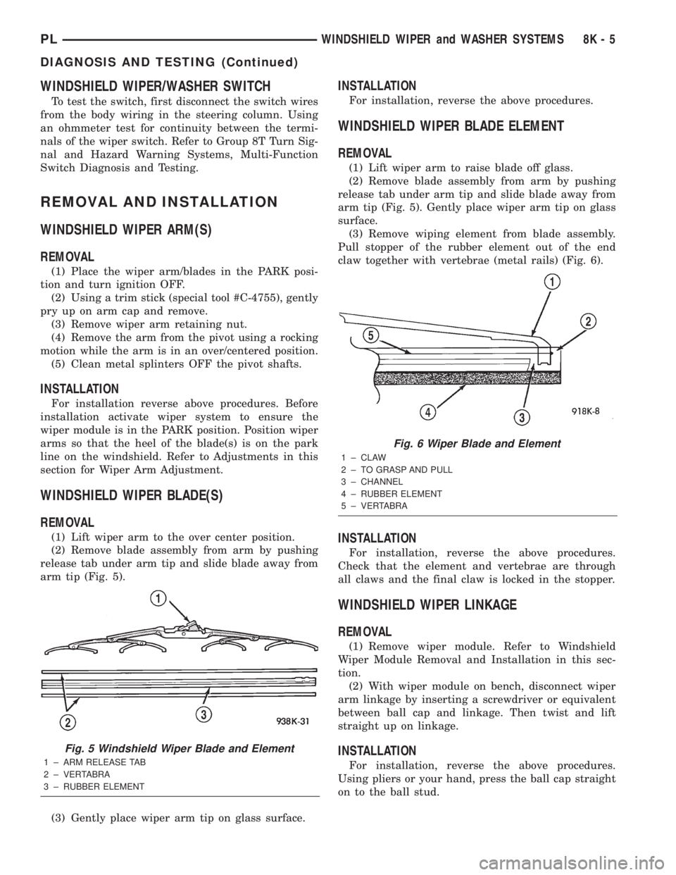
WINDSHIELD WIPER/WASHER SWITCH
To test the switch, first disconnect the switch wires
from the body wiring in the steering column. Using
an ohmmeter test for continuity between the termi-
nals of the wiper switch. Refer to Group 8T Turn Sig-
nal and Hazard Warning Systems, Multi-Function
Switch Diagnosis and Testing.
REMOVAL AND INSTALLATION
WINDSHIELD WIPER ARM(S)
REMOVAL
(1) Place the wiper arm/blades in the PARK posi-
tion and turn ignition OFF.
(2) Using a trim stick (special tool #C-4755), gently
pry up on arm cap and remove.
(3) Remove wiper arm retaining nut.
(4) Remove the arm from the pivot using a rocking
motion while the arm is in an over/centered position.
(5) Clean metal splinters OFF the pivot shafts.
INSTALLATION
For installation reverse above procedures. Before
installation activate wiper system to ensure the
wiper module is in the PARK position. Position wiper
arms so that the heel of the blade(s) is on the park
line on the windshield. Refer to Adjustments in this
section for Wiper Arm Adjustment.
WINDSHIELD WIPER BLADE(S)
REMOVAL
(1) Lift wiper arm to the over center position.
(2) Remove blade assembly from arm by pushing
release tab under arm tip and slide blade away from
arm tip (Fig. 5).
(3) Gently place wiper arm tip on glass surface.
INSTALLATION
For installation, reverse the above procedures.
WINDSHIELD WIPER BLADE ELEMENT
REMOVAL
(1) Lift wiper arm to raise blade off glass.
(2) Remove blade assembly from arm by pushing
release tab under arm tip and slide blade away from
arm tip (Fig. 5). Gently place wiper arm tip on glass
surface.
(3) Remove wiping element from blade assembly.
Pull stopper of the rubber element out of the end
claw together with vertebrae (metal rails) (Fig. 6).
INSTALLATION
For installation, reverse the above procedures.
Check that the element and vertebrae are through
all claws and the final claw is locked in the stopper.
WINDSHIELD WIPER LINKAGE
REMOVAL
(1) Remove wiper module. Refer to Windshield
Wiper Module Removal and Installation in this sec-
tion.
(2) With wiper module on bench, disconnect wiper
arm linkage by inserting a screwdriver or equivalent
between ball cap and linkage. Then twist and lift
straight up on linkage.
INSTALLATION
For installation, reverse the above procedures.
Using pliers or your hand, press the ball cap straight
on to the ball stud.
Fig. 5 Windshield Wiper Blade and Element
1 ± ARM RELEASE TAB
2 ± VERTABRA
3 ± RUBBER ELEMENT
Fig. 6 Wiper Blade and Element
1 ± CLAW
2 ± TO GRASP AND PULL
3 ± CHANNEL
4 ± RUBBER ELEMENT
5 ± VERTABRA
PLWINDSHIELD WIPER and WASHER SYSTEMS 8K - 5
DIAGNOSIS AND TESTING (Continued)
Page 303 of 1285
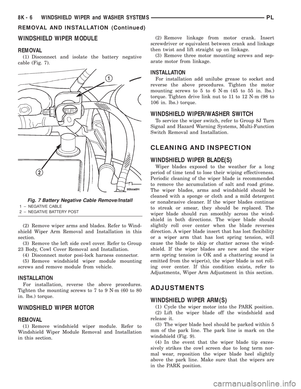
WINDSHIELD WIPER MODULE
REMOVAL
(1) Disconnect and isolate the battery negative
cable (Fig. 7).
(2) Remove wiper arms and blades. Refer to Wind-
shield Wiper Arm Removal and Installation in this
section.
(3) Remove the left side cowl cover. Refer to Group
23 Body, Cowl Cover Removal and Installation.
(4) Disconnect motor posi-lock harness connector.
(5) Remove windshield wiper module mounting
screws and remove module from vehicle.
INSTALLATION
For installation, reverse the above procedures.
Tighten the mounting screws to 7 to 9 N´m (60 to 80
in. lbs.) torque.
WINDSHIELD WIPER MOTOR
REMOVAL
(1) Remove windshield wiper module. Refer to
Windshield Wiper Module Removal and Installation
in this section.(2) Remove linkage from motor crank. Insert
screwdriver or equivalent between crank and linkage
then twist and lift straight up on linkage.
(3) Remove three motor mounting screws and sep-
arate motor from linkage.
INSTALLATION
For installation add unilube grease to socket and
reverse the above procedures. Tighten the motor
mounting screws to 5 to 6 N´m (45 to 55 in. lbs.)
torque. Tighten drive link nut to 11 to 12 N´m (98 to
106 in. lbs.) torque.
WINDSHIELD WIPER/WASHER SWITCH
To service the wiper switch, refer to Group 8J Turn
Signal and Hazard Warning Systems, Multi-Function
Switch Removal and Installation.
CLEANING AND INSPECTION
WINDSHIELD WIPER BLADE(S)
Wiper blades exposed to the weather for a long
period of time tend to lose their wiping effectiveness.
Periodic cleaning of the wiper blade is recommended
to remove the accumulation of salt and road grime.
The wiper blades, arms and windshield should be
cleaned with a sponge or cloth and a mild detergent
or nonabrasive cleaner. If the wiper blades continue
to streak or smear, they should be replaced. The
wiper blade should run smoothly across the wind-
shield in both directions. The wiper blade should
slightly roll over center when the blade reverses
direction. A wiper blade insert that has lost flexibility
or a wiper arm that has lost spring tension, will
cause the blade to skip or chatter across the wind-
shield. If the wiper blades are new and the wiper
arm spring tension is OK and a chattering sound is
emitted from the wiper(s), the wiper blade is not roll-
ing over center. If this condition exists, refer to
Adjustments, Wiper Arm Adjustment in this section.
ADJUSTMENTS
WINDSHIELD WIPER ARM(S)
(1) Cycle the wiper motor into the PARK position.
(2) Lift the wiper blade off the windshield and
release it.
(3) The wiper blade heel should be parked within 5
mm of the park line. The park line is mark on the
windshield (Fig. 9).
(4) In the event that the wiper blade tip exces-
sively strikes the cowl screen due to long term nor-
mal wear, reposition the wiper blade heel slightly
above the park line. Make sure that the wipers are
in the PARK position.
Fig. 7 Battery Negative Cable Remove/Install
1 ± NEGATIVE CABLE
2 ± NEGATIVE BATTERY POST
8K - 6 WINDSHIELD WIPER and WASHER SYSTEMSPL
REMOVAL AND INSTALLATION (Continued)
Page 304 of 1285
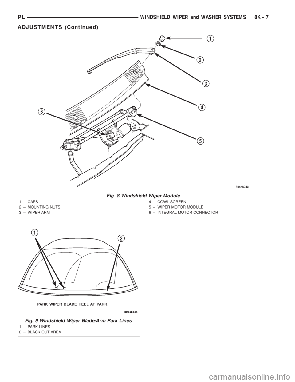
Fig. 8 Windshield Wiper Module
1 ± CAPS
2 ± MOUNTING NUTS
3 ± WIPER ARM4 ± COWL SCREEN
5 ± WIPER MOTOR MODULE
6 ± INTEGRAL MOTOR CONNECTOR
Fig. 9 Windshield Wiper Blade/Arm Park Lines
1 ± PARK LINES
2 ± BLACK OUT AREA
PLWINDSHIELD WIPER and WASHER SYSTEMS 8K - 7
ADJUSTMENTS (Continued)
Page 305 of 1285
WINDSHIELD WASHER SYSTEM
TABLE OF CONTENTS
page page
DESCRIPTION AND OPERATION
WINDSHIELD WASHER NOZZLE(S)............8
WINDSHIELD WASHER SYSTEM.............8
DIAGNOSIS AND TESTING
WINDSHIELD WASHER SYSTEM.............9REMOVAL AND INSTALLATION
WINDSHIELD WASHER HOSE................9
WINDSHIELD WASHER NOZZLES.............9
WINDSHIELD WASHER RESERVOIR..........10
WINDSHIELD WASHER PUMP...............10
DESCRIPTION AND OPERATION
WINDSHIELD WASHER NOZZLE(S)
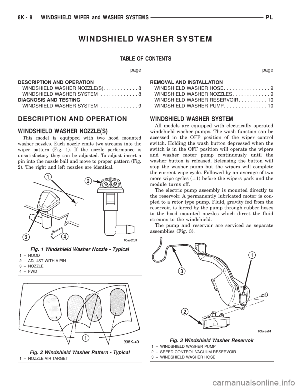
This model is equipped with two hood mounted
washer nozzles. Each nozzle emits two streams into the
wiper pattern (Fig. 1). If the nozzle performance is
unsatisfactory they can be adjusted. To adjust insert a
pin into the nozzle ball and move to proper pattern (Fig.
2). The right and left nozzles are identical.
WINDSHIELD WASHER SYSTEM
All models are equipped with electrically operated
windshield washer pumps. The wash function can be
accessed in the OFF position of the wiper control
switch. Holding the wash button depressed when the
switch is in the OFF position will operate the wipers
and washer motor pump continuously until the
washer button is released. Releasing the button will
stop the washer pump but the wipers will complete
the current wipe cycle. Followed by an average of two
more wipe cycles (61) before the wipers park and the
module turns off.
The electric pump assembly is mounted directly to
the reservoir. A permanently lubricated motor is cou-
pled to a rotor type pump. Fluid, gravity fed from the
reservoir, is forced by the pump through rubber hoses
to the hood mounted nozzles which direct the fluid
streams to the windshield.
The pump and reservoir are serviced as separate
assemblies (Fig. 3).
Fig. 1 Windshield Washer Nozzle - Typical
1 ± HOOD
2 ± ADJUST WITH A PIN
3 ± NOZZLE
4 ± FWD
Fig. 2 Windshield Washer Pattern - Typical
1 ± NOZZLE AIR TARGET
Fig. 3 Windshield Washer Reservoir
1 ± WINDSHIELD WASHER PUMP
2 ± SPEED CONTROL VACUUM RESERVOIR
3 ± WINDSHIELD WASHER HOSE
8K - 8 WINDSHIELD WIPER and WASHER SYSTEMSPL
Page 306 of 1285
DIAGNOSIS AND TESTING
WINDSHIELD WASHER SYSTEM
Whenever a windshield washer malfunction occurs,
first verify that the windshield washer wire harnessis properly connected to all connectors before starting
normal diagnosis and repair procedures. Refer to
Windshield Washer System Test table.
WINDSHIELD WASHER SYSTEM TEST
CONDITION POSSIBLE CAUSE CORRECTION
PUMP RUNS NO FLUID
FLOWING.1. NO FLUID IN THE
RESERVOIR.
2. NOZZLE PLUGGED
OR FROZEN.
3. BROKEN, LOOSE OR
PINCHED HOSE.
4. FAULTY PUMP.1. FILL RESERVOIR.
2. THAW AND CHECK FLOW IF BLOCKED
3. CHECK FLOW THROUGH HOSE CONNECTIONS.
4. APPLY BATTERY VOLTAGE TO MOTOR
TERMINALS, REPLACE IF PUMP DOES NOT RUN.
SYSTEM OPERATES
INTERMITTENTLY.1. LOOSE WIRE
CONNECTION.
2. FAULTY SWITCH.1. CHECK WIRE CONNECTIONS.
2. DISCONNECT WIRE HARNESS USE
VOLTMETER TO CHECK SWITCH.
SYSTEM OUTPUT IS
LOW.1. PINCHED HOSE.
2. HOSE BLOCKED.1. CHECK FLOW THROUGH HOSE CONNECTION.
2. DISCONNECT HOSE AT NOZZLE AND Y
CONNECTOR CHECK FOR FLOW. REPLACE ASS
NECESSARY.
REMOVAL AND INSTALLATION
WINDSHIELD WASHER HOSE
REMOVAL
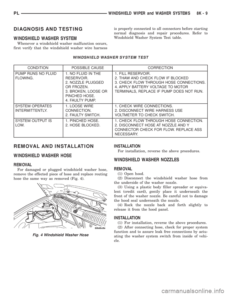
For damaged or plugged windshield washer hose,
remove the effected piece of hose and replace routing
hose the same way as removed (Fig. 4).
INSTALLATION
For installation, reverse the above procedures.
WINDSHIELD WASHER NOZZLES
REMOVAL
(1) Open hood.
(2) Disconnect the windshield washer hose from
the underside of the washer nozzle.
(3) Using a plastic body filler spreader or equiva-
lent (credit card), gently place it underneath the
front of the washer nozzle. Be careful not to damage
the hood seal underneath the nozzle.
(4) Rock the nozzle back and forth slightly to
release it from the hood panel.
INSTALLATION
(1) For installation, reverse the above procedures.
(2) After connecting hose, check for proper system
function and to assure leak free connections by actu-
ating the washer system switch from inside of vehi-
cle.
Fig. 4 Windshield Washer Hose
PLWINDSHIELD WIPER and WASHER SYSTEMS 8K - 9
Page 307 of 1285
WINDSHIELD WASHER RESERVOIR
REMOVAL
(1) Raise vehicle on hoist.
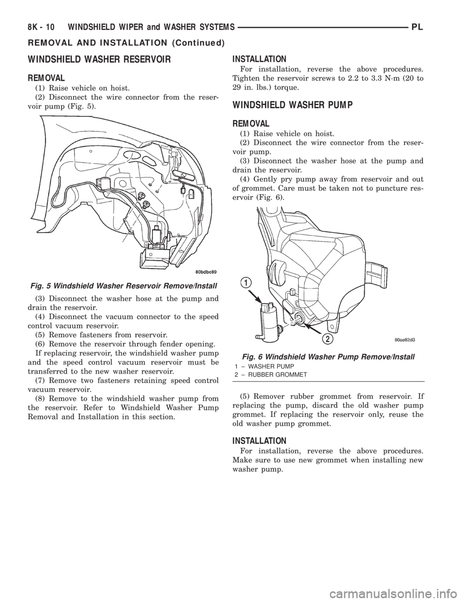
(2) Disconnect the wire connector from the reser-
voir pump (Fig. 5).
(3) Disconnect the washer hose at the pump and
drain the reservoir.
(4) Disconnect the vacuum connector to the speed
control vacuum reservoir.
(5) Remove fasteners from reservoir.
(6) Remove the reservoir through fender opening.
If replacing reservoir, the windshield washer pump
and the speed control vacuum reservoir must be
transferred to the new washer reservoir.
(7) Remove two fasteners retaining speed control
vacuum reservoir.
(8) Remove to the windshield washer pump from
the reservoir. Refer to Windshield Washer Pump
Removal and Installation in this section.
INSTALLATION
For installation, reverse the above procedures.
Tighten the reservoir screws to 2.2 to 3.3 N´m (20 to
29 in. lbs.) torque.
WINDSHIELD WASHER PUMP
REMOVAL
(1) Raise vehicle on hoist.
(2) Disconnect the wire connector from the reser-
voir pump.
(3) Disconnect the washer hose at the pump and
drain the reservoir.
(4) Gently pry pump away from reservoir and out
of grommet. Care must be taken not to puncture res-
ervoir (Fig. 6).
(5) Remover rubber grommet from reservoir. If
replacing the pump, discard the old washer pump
grommet. If replacing the reservoir only, reuse the
old washer pump grommet.
INSTALLATION
For installation, reverse the above procedures.
Make sure to use new grommet when installing new
washer pump.
Fig. 5 Windshield Washer Reservoir Remove/Install
Fig. 6 Windshield Washer Pump Remove/Install
1 ± WASHER PUMP
2 ± RUBBER GROMMET
8K - 10 WINDSHIELD WIPER and WASHER SYSTEMSPL
REMOVAL AND INSTALLATION (Continued)
Page 308 of 1285
LAMPS
TABLE OF CONTENTS
page page
LAMP DIAGNOSIS......................... 1
HEADLAMP ALIGNMENT.................... 4
LAMP BULB SERVICE...................... 7LAMP SERVICE........................... 12
LAMP SYSTEMS.......................... 16
BULB APPLICATION....................... 17
LAMP DIAGNOSIS
TABLE OF CONTENTS
page page
DESCRIPTION AND OPERATION
DIAGNOSTIC PROCEDURES................1
SAFETY PRECAUTIONS....................1
DAYTIME RUNNING LAMP MODULE...........1DIAGNOSIS AND TESTING
HEADLAMP DIAGNOSIS....................1
FOG LAMP..............................3
DESCRIPTION AND OPERATION
DIAGNOSTIC PROCEDURES
When a vehicle experiences problems with the
headlamp system, verify the condition of the battery
connections, fuses, charging system, headlamp bulbs,
wire connectors, relay, high beam switch, dimmer
switch, and headlamp switch. Refer to Group 8W,
Wiring Diagrams for component locations and circuit
information.
SAFETY PRECAUTIONS
WARNING: EYE PROTECTION SHOULD BE USED
WHEN SERVICING GLASS COMPONENTS. PER-
SONAL INJURY CAN RESULT.
CAUTION: Do not touch the glass of halogen bulbs
with fingers or other possibly oily surface, reduced
bulb life will result.
Do not use bulbs with higher candle power than
indicated in the Bulb Application table at the end of
this group. Damage to lamp and/or Daytime Run-
ning Lamp Module can result.
Do not use fuses, circuit breakers or relays hav-
ing greater amperage value than indicated on the
fuse panel or in the Owners Manual.When it is necessary to remove components to ser-
vice another, it should not be necessary to apply
excessive force or bend a component to remove it.
Before damaging a trim component, verify hidden
fasteners or captured edges are not holding the com-
ponent in place.
DAYTIME RUNNING LAMP MODULE
PL vehicles built for use in Canada are equipped
with a Daytime Running Lamp (DRL) system. Turn
signal lamp circuitry always comes from the multi-
function switch, and goes to the cluster connector,
into the cluster, then back out to the front turn sig-
nal switch lamps. The Canadian cluster provides
steady illumination of the front turn signal when the
ignition switch is in the ON position. The DRL func-
tion may be inhibited by activating the turn signals,
the hazard flashers, the headlamp switch, or park
brake.
DIAGNOSIS AND TESTING
HEADLAMP DIAGNOSIS
Always begin any diagnosis by testing all of the
fuses and circuit breakers in the system. Refer to
Group 8W, Wiring Diagrams.
Conventional and halogen headlamps are inter-
changeable. It is recommended that they not be
intermixed on a given vehicle.
PLLAMPS 8L - 1
Page 309 of 1285
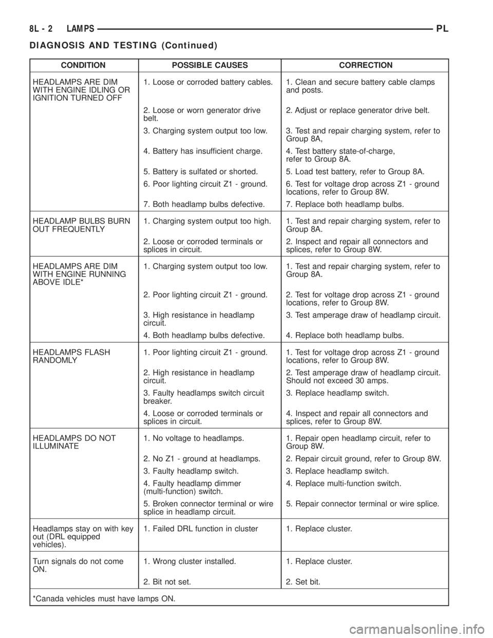
CONDITION POSSIBLE CAUSES CORRECTION
HEADLAMPS ARE DIM
WITH ENGINE IDLING OR
IGNITION TURNED OFF1. Loose or corroded battery cables. 1. Clean and secure battery cable clamps
and posts.
2. Loose or worn generator drive
belt.2. Adjust or replace generator drive belt.
3. Charging system output too low. 3. Test and repair charging system, refer to
Group 8A,
4. Battery has insufficient charge. 4. Test battery state-of-charge,
refer to Group 8A.
5. Battery is sulfated or shorted. 5. Load test battery, refer to Group 8A.
6. Poor lighting circuit Z1 - ground. 6. Test for voltage drop across Z1 - ground
locations, refer to Group 8W.
7. Both headlamp bulbs defective. 7. Replace both headlamp bulbs.
HEADLAMP BULBS BURN
OUT FREQUENTLY1. Charging system output too high. 1. Test and repair charging system, refer to
Group 8A.
2. Loose or corroded terminals or
splices in circuit.2. Inspect and repair all connectors and
splices, refer to Group 8W.
HEADLAMPS ARE DIM
WITH ENGINE RUNNING
ABOVE IDLE*1. Charging system output too low. 1. Test and repair charging system, refer to
Group 8A.
2. Poor lighting circuit Z1 - ground. 2. Test for voltage drop across Z1 - ground
locations, refer to Group 8W.
3. High resistance in headlamp
circuit.3. Test amperage draw of headlamp circuit.
4. Both headlamp bulbs defective. 4. Replace both headlamp bulbs.
HEADLAMPS FLASH
RANDOMLY1. Poor lighting circuit Z1 - ground. 1. Test for voltage drop across Z1 - ground
locations, refer to Group 8W.
2. High resistance in headlamp
circuit.2. Test amperage draw of headlamp circuit.
Should not exceed 30 amps.
3. Faulty headlamps switch circuit
breaker.3. Replace headlamp switch.
4. Loose or corroded terminals or
splices in circuit.4. Inspect and repair all connectors and
splices, refer to Group 8W.
HEADLAMPS DO NOT
ILLUMINATE1. No voltage to headlamps. 1. Repair open headlamp circuit, refer to
Group 8W.
2. No Z1 - ground at headlamps. 2. Repair circuit ground, refer to Group 8W.
3. Faulty headlamp switch. 3. Replace headlamp switch.
4. Faulty headlamp dimmer
(multi-function) switch.4. Replace multi-function switch.
5. Broken connector terminal or wire
splice in headlamp circuit.5. Repair connector terminal or wire splice.
Headlamps stay on with key
out (DRL equipped
vehicles).1. Failed DRL function in cluster 1. Replace cluster.
Turn signals do not come
ON.1. Wrong cluster installed. 1. Replace cluster.
2. Bit not set. 2. Set bit.
*Canada vehicles must have lamps ON.
8L - 2 LAMPSPL
DIAGNOSIS AND TESTING (Continued)
Page 310 of 1285
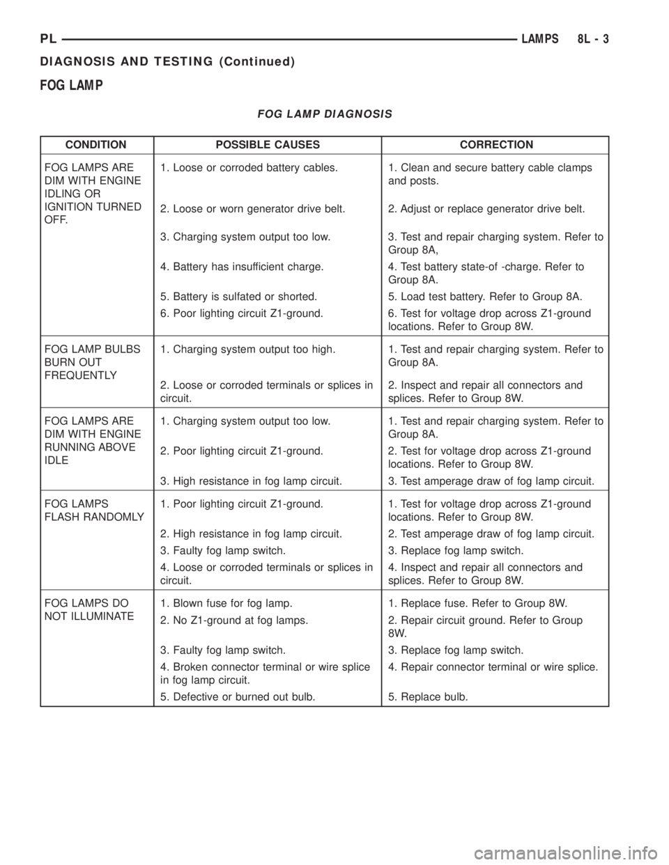
FOG LAMP
FOG LAMP DIAGNOSIS
CONDITION POSSIBLE CAUSES CORRECTION
FOG LAMPS ARE
DIM WITH ENGINE
IDLING OR
IGNITION TURNED
OFF.1. Loose or corroded battery cables. 1. Clean and secure battery cable clamps
and posts.
2. Loose or worn generator drive belt. 2. Adjust or replace generator drive belt.
3. Charging system output too low. 3. Test and repair charging system. Refer to
Group 8A,
4. Battery has insufficient charge. 4. Test battery state-of -charge. Refer to
Group 8A.
5. Battery is sulfated or shorted. 5. Load test battery. Refer to Group 8A.
6. Poor lighting circuit Z1-ground. 6. Test for voltage drop across Z1-ground
locations. Refer to Group 8W.
FOG LAMP BULBS
BURN OUT
FREQUENTLY1. Charging system output too high. 1. Test and repair charging system. Refer to
Group 8A.
2. Loose or corroded terminals or splices in
circuit.2. Inspect and repair all connectors and
splices. Refer to Group 8W.
FOG LAMPS ARE
DIM WITH ENGINE
RUNNING ABOVE
IDLE1. Charging system output too low. 1. Test and repair charging system. Refer to
Group 8A.
2. Poor lighting circuit Z1-ground. 2. Test for voltage drop across Z1-ground
locations. Refer to Group 8W.
3. High resistance in fog lamp circuit. 3. Test amperage draw of fog lamp circuit.
FOG LAMPS
FLASH RANDOMLY1. Poor lighting circuit Z1-ground. 1. Test for voltage drop across Z1-ground
locations. Refer to Group 8W.
2. High resistance in fog lamp circuit. 2. Test amperage draw of fog lamp circuit.
3. Faulty fog lamp switch. 3. Replace fog lamp switch.
4. Loose or corroded terminals or splices in
circuit.4. Inspect and repair all connectors and
splices. Refer to Group 8W.
FOG LAMPS DO
NOT ILLUMINATE1. Blown fuse for fog lamp. 1. Replace fuse. Refer to Group 8W.
2. No Z1-ground at fog lamps. 2. Repair circuit ground. Refer to Group
8W.
3. Faulty fog lamp switch. 3. Replace fog lamp switch.
4. Broken connector terminal or wire splice
in fog lamp circuit.4. Repair connector terminal or wire splice.
5. Defective or burned out bulb. 5. Replace bulb.
PLLAMPS 8L - 3
DIAGNOSIS AND TESTING (Continued)