DODGE NEON 2000 Service Repair Manual
Manufacturer: DODGE, Model Year: 2000, Model line: NEON, Model: DODGE NEON 2000Pages: 1285, PDF Size: 29.42 MB
Page 291 of 1285

Page 292 of 1285
TURN SIGNAL and HAZARD WARNING SYSTEMS
TABLE OF CONTENTS
page page
GENERAL INFORMATION
INTRODUCTION..........................1
DESCRIPTION AND OPERATION
HAZARD WARNING SYSTEM................2
HEADLAMP SWITCH......................2
COMBINATION FLASHER...................2DIAGNOSIS AND TESTING
MULTI-FUNCTION SWITCH.................3
REMOVAL AND INSTALLATION
COMBINATION FLASHER...................5
MULTI-FUNCTION SWITCH.................5
GENERAL INFORMATION
INTRODUCTION
WARNING: ON VEHICLES EQUIPPED WITH AIR-
BAG, SEE GROUP 8M, PASSIVE RESTRAINT SYS-
TEMS FOR AIRBAG REMOVAL.
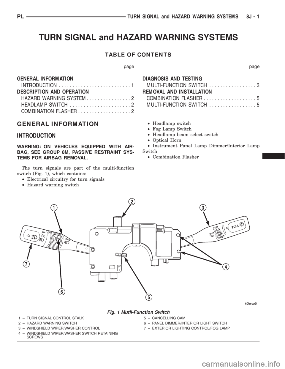
The turn signals are part of the multi-function
switch (Fig. 1), which contains:
²Electrical circuitry for turn signals
²Hazard warning switch²Headlamp switch
²Fog Lamp Switch
²Headlamp beam select switch
²Optical Horn
²Instrument Panel Lamp Dimmer/Interior Lamp
Switch
²Combination Flasher
Fig. 1 Mutli-Function Switch
1 ± TURN SIGNAL CONTROL STALK
2 ± HAZARD WARNING SWITCH
3 ± WINDSHIELD WIPER/WASHER CONTROL
4 ± WINDSHIELD WIPER/WASHER SWITCH RETAINING
SCREWS5 ± CANCELLING CAM
6 ± PANEL DIMMER/INTERIOR LIGHT SWITCH
7 ± EXTERIOR LIGHTING CONTROL/FOG LAMP
PLTURN SIGNAL and HAZARD WARNING SYSTEMS 8J - 1
Page 293 of 1285
The integrated switch assembly is mounted to the
left hand side of the steering column. When the
driver wishes to signal his intentions to change direc-
tion of travel, he moves the lever upward to cause
the right signals to flash and downward to cause the
left signals to flash. After completion of a turn the
system is deactivated automatically. As the steering
wheel returns to the straight ahead position, a can-
celing cam molded to the clockspring mechanism
comes in contact with the cancel actuator on the turn
signal multi-function switch assembly. The cam lobe,
pushing on the cancel actuator, returns the switch to
the off position.
If only momentary signaling such as indication of a
lane change is desired, the switch is actuated to a
left or right intermediate detent position. In this
position the signal lamps flash as described above,
but the switch returns to the OFF position as soon as
the lever is released.
When the system is activated, one of two indicator
lamps mounted in the instrument cluster flashes in
unison with the turn signal lamps, indicating to the
driver that the system is operating.
DESCRIPTION AND OPERATION
HAZARD WARNING SYSTEM
The hazard warning system is actuated by a push
button located in the muti-function switch (Fig. 1) on
the top of the steering column between the steering
wheel and the instrument panel. The hazard switch
is identified with a double triangle on front of the
button.
HEADLAMP SWITCH
The headlamp switch is part of the Multi-Function
Switch (Fig. 1). Refer to Multi-Function Switch Diag-
nosis and Testing, Turn Signal and Hazard Warning
Flasher Diagnosis table in this section.
COMBINATION FLASHER
The turn signal flasher and the hazard warning
flasher are combined into one unit called a combina-
tion flasher (combo-flasher). The combo- flasher con-
trols the flashing of the hazard warning system and
the turn signal system. An inoperative bulb or incom-
plete turn signal circuit will cause the flasher rate to
double.
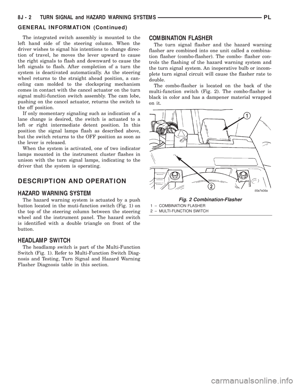
The combo-flasher is located on the back of the
multi-function switch (Fig. 2). The combo-flasher is
black in color and has a dampener material wrapped
on it.
Fig. 2 Combination-Flasher
1 ± COMBINATION FLASHER
2 ± MULTI-FUNCTION SWITCH
8J - 2 TURN SIGNAL and HAZARD WARNING SYSTEMSPL
GENERAL INFORMATION (Continued)
Page 294 of 1285
DIAGNOSIS AND TESTING
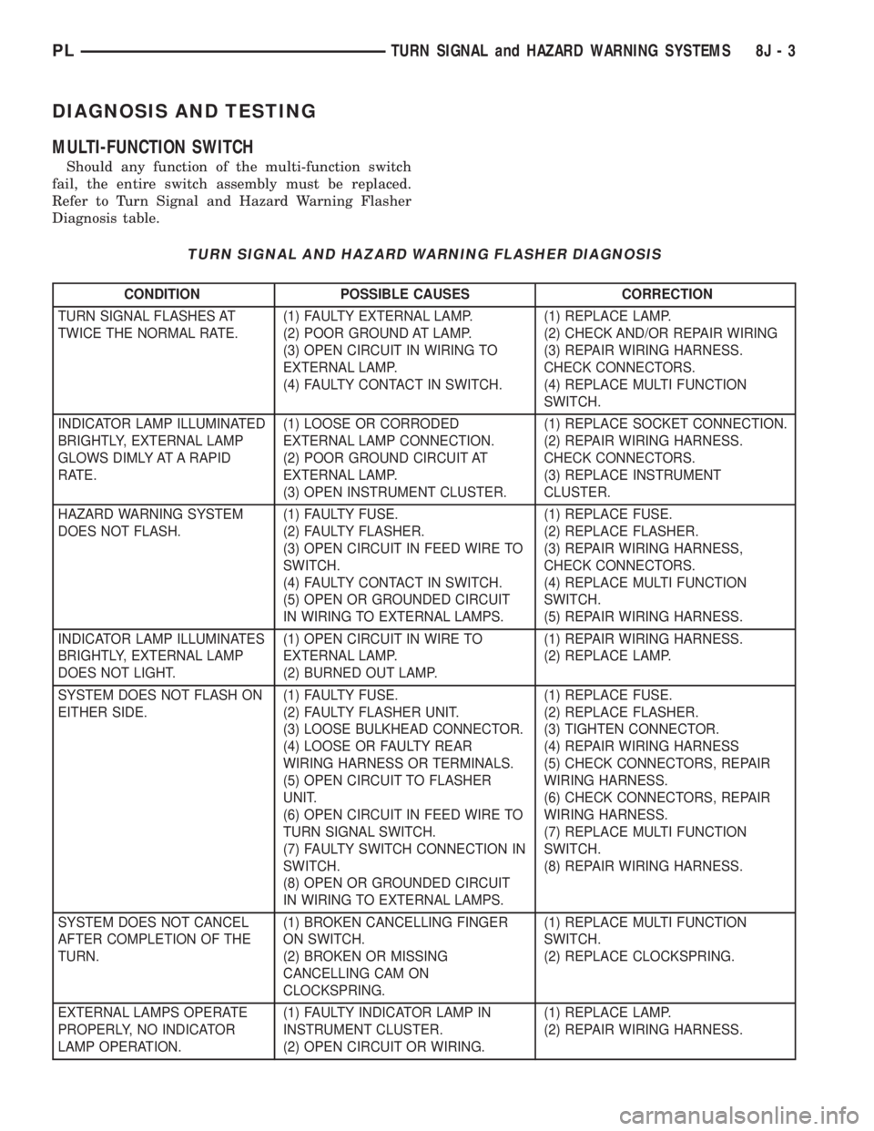
MULTI-FUNCTION SWITCH
Should any function of the multi-function switch
fail, the entire switch assembly must be replaced.
Refer to Turn Signal and Hazard Warning Flasher
Diagnosis table.
TURN SIGNAL AND HAZARD WARNING FLASHER DIAGNOSIS
CONDITION POSSIBLE CAUSES CORRECTION
TURN SIGNAL FLASHES AT
TWICE THE NORMAL RATE.(1) FAULTY EXTERNAL LAMP.
(2) POOR GROUND AT LAMP.
(3) OPEN CIRCUIT IN WIRING TO
EXTERNAL LAMP.
(4) FAULTY CONTACT IN SWITCH.(1) REPLACE LAMP.
(2) CHECK AND/OR REPAIR WIRING
(3) REPAIR WIRING HARNESS.
CHECK CONNECTORS.
(4) REPLACE MULTI FUNCTION
SWITCH.
INDICATOR LAMP ILLUMINATED
BRIGHTLY, EXTERNAL LAMP
GLOWS DIMLY AT A RAPID
RATE.(1) LOOSE OR CORRODED
EXTERNAL LAMP CONNECTION.
(2) POOR GROUND CIRCUIT AT
EXTERNAL LAMP.
(3) OPEN INSTRUMENT CLUSTER.(1) REPLACE SOCKET CONNECTION.
(2) REPAIR WIRING HARNESS.
CHECK CONNECTORS.
(3) REPLACE INSTRUMENT
CLUSTER.
HAZARD WARNING SYSTEM
DOES NOT FLASH.(1) FAULTY FUSE.
(2) FAULTY FLASHER.
(3) OPEN CIRCUIT IN FEED WIRE TO
SWITCH.
(4) FAULTY CONTACT IN SWITCH.
(5) OPEN OR GROUNDED CIRCUIT
IN WIRING TO EXTERNAL LAMPS.(1) REPLACE FUSE.
(2) REPLACE FLASHER.
(3) REPAIR WIRING HARNESS,
CHECK CONNECTORS.
(4) REPLACE MULTI FUNCTION
SWITCH.
(5) REPAIR WIRING HARNESS.
INDICATOR LAMP ILLUMINATES
BRIGHTLY, EXTERNAL LAMP
DOES NOT LIGHT.(1) OPEN CIRCUIT IN WIRE TO
EXTERNAL LAMP.
(2) BURNED OUT LAMP.(1) REPAIR WIRING HARNESS.
(2) REPLACE LAMP.
SYSTEM DOES NOT FLASH ON
EITHER SIDE.(1) FAULTY FUSE.
(2) FAULTY FLASHER UNIT.
(3) LOOSE BULKHEAD CONNECTOR.
(4) LOOSE OR FAULTY REAR
WIRING HARNESS OR TERMINALS.
(5) OPEN CIRCUIT TO FLASHER
UNIT.
(6) OPEN CIRCUIT IN FEED WIRE TO
TURN SIGNAL SWITCH.
(7) FAULTY SWITCH CONNECTION IN
SWITCH.
(8) OPEN OR GROUNDED CIRCUIT
IN WIRING TO EXTERNAL LAMPS.(1) REPLACE FUSE.
(2) REPLACE FLASHER.
(3) TIGHTEN CONNECTOR.
(4) REPAIR WIRING HARNESS
(5) CHECK CONNECTORS, REPAIR
WIRING HARNESS.
(6) CHECK CONNECTORS, REPAIR
WIRING HARNESS.
(7) REPLACE MULTI FUNCTION
SWITCH.
(8) REPAIR WIRING HARNESS.
SYSTEM DOES NOT CANCEL
AFTER COMPLETION OF THE
TURN.(1) BROKEN CANCELLING FINGER
ON SWITCH.
(2) BROKEN OR MISSING
CANCELLING CAM ON
CLOCKSPRING.(1) REPLACE MULTI FUNCTION
SWITCH.
(2) REPLACE CLOCKSPRING.
EXTERNAL LAMPS OPERATE
PROPERLY, NO INDICATOR
LAMP OPERATION.(1) FAULTY INDICATOR LAMP IN
INSTRUMENT CLUSTER.
(2) OPEN CIRCUIT OR WIRING.(1) REPLACE LAMP.
(2) REPAIR WIRING HARNESS.
PLTURN SIGNAL and HAZARD WARNING SYSTEMS 8J - 3
Page 295 of 1285
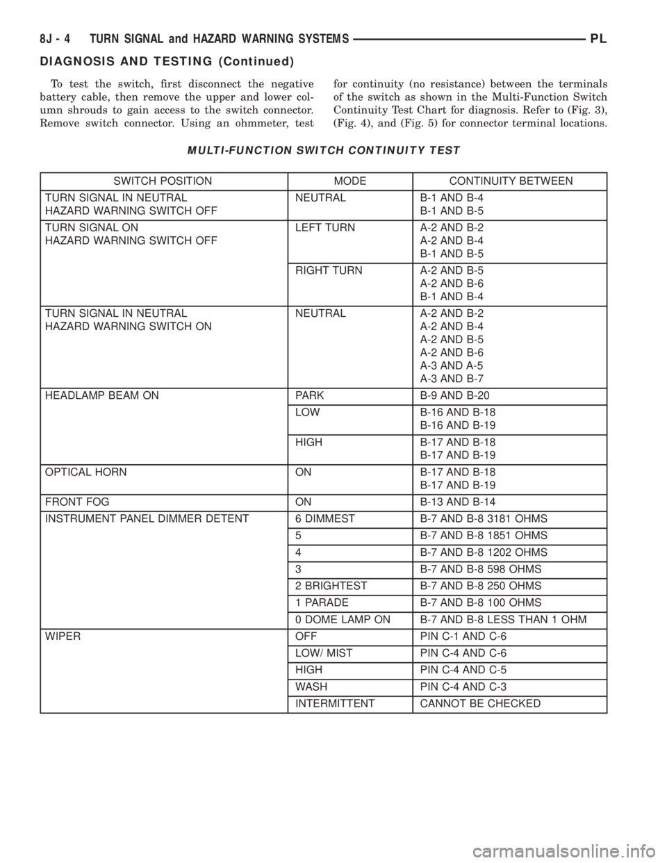
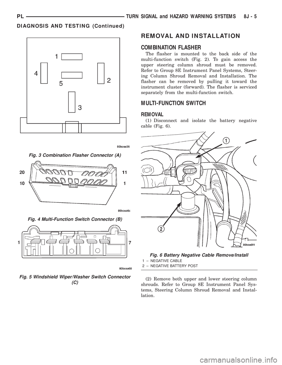
To test the switch, first disconnect the negative
battery cable, then remove the upper and lower col-
umn shrouds to gain access to the switch connector.
Remove switch connector. Using an ohmmeter, testfor continuity (no resistance) between the terminals
of the switch as shown in the Multi-Function Switch
Continuity Test Chart for diagnosis. Refer to (Fig. 3),
(Fig. 4), and (Fig. 5) for connector terminal locations.
MULTI-FUNCTION SWITCH CONTINUITY TEST
SWITCH POSITION MODE CONTINUITY BETWEEN
TURN SIGNAL IN NEUTRAL
HAZARD WARNING SWITCH OFFNEUTRAL B-1 AND B-4
B-1 AND B-5
TURN SIGNAL ON
HAZARD WARNING SWITCH OFFLEFT TURN A-2 AND B-2
A-2 AND B-4
B-1 AND B-5
RIGHT TURN A-2 AND B-5
A-2 AND B-6
B-1 AND B-4
TURN SIGNAL IN NEUTRAL
HAZARD WARNING SWITCH ONNEUTRAL A-2 AND B-2
A-2 AND B-4
A-2 AND B-5
A-2 AND B-6
A-3 AND A-5
A-3 AND B-7
HEADLAMP BEAM ON PARK B-9 AND B-20
LOW B-16 AND B-18
B-16 AND B-19
HIGH B-17 AND B-18
B-17 AND B-19
OPTICAL HORN ON B-17 AND B-18
B-17 AND B-19
FRONT FOG ON B-13 AND B-14
INSTRUMENT PANEL DIMMER DETENT 6 DIMMEST B-7 AND B-8 3181 OHMS
5 B-7 AND B-8 1851 OHMS
4 B-7 AND B-8 1202 OHMS
3 B-7 AND B-8 598 OHMS
2 BRIGHTEST B-7 AND B-8 250 OHMS
1 PARADE B-7 AND B-8 100 OHMS
0 DOME LAMP ON B-7 AND B-8 LESS THAN 1 OHM
WIPER OFF PIN C-1 AND C-6
LOW/ MIST PIN C-4 AND C-6
HIGH PIN C-4 AND C-5
WASH PIN C-4 AND C-3
INTERMITTENT CANNOT BE CHECKED
8J - 4 TURN SIGNAL and HAZARD WARNING SYSTEMSPL
DIAGNOSIS AND TESTING (Continued)
Page 296 of 1285
REMOVAL AND INSTALLATION
COMBINATION FLASHER
The flasher is mounted to the back side of the
multi-function switch (Fig. 2). To gain access the
upper steering column shroud must be removed.
Refer to Group 8E Instrument Panel Systems, Steer-
ing Column Shroud Removal and Installation. The
flasher can be removed by pulling it toward the
instrument cluster (forward). The flasher is serviced
separately from the multi-function switch.
MULTI-FUNCTION SWITCH
REMOVAL
(1) Disconnect and isolate the battery negative
cable (Fig. 6).
(2) Remove both upper and lower steering column
shrouds. Refer to Group 8E Instrument Panel Sys-
tems, Steering Column Shroud Removal and Instal-
lation.
Fig. 3 Combination Flasher Connector (A)
Fig. 4 Multi-Function Switch Connector (B)
Fig. 5 Windshield Wiper/Washer Switch Connector
(C)
Fig. 6 Battery Negative Cable Remove/Install
1 ± NEGATIVE CABLE
2 ± NEGATIVE BATTERY POST
PLTURN SIGNAL and HAZARD WARNING SYSTEMS 8J - 5
DIAGNOSIS AND TESTING (Continued)
Page 297 of 1285
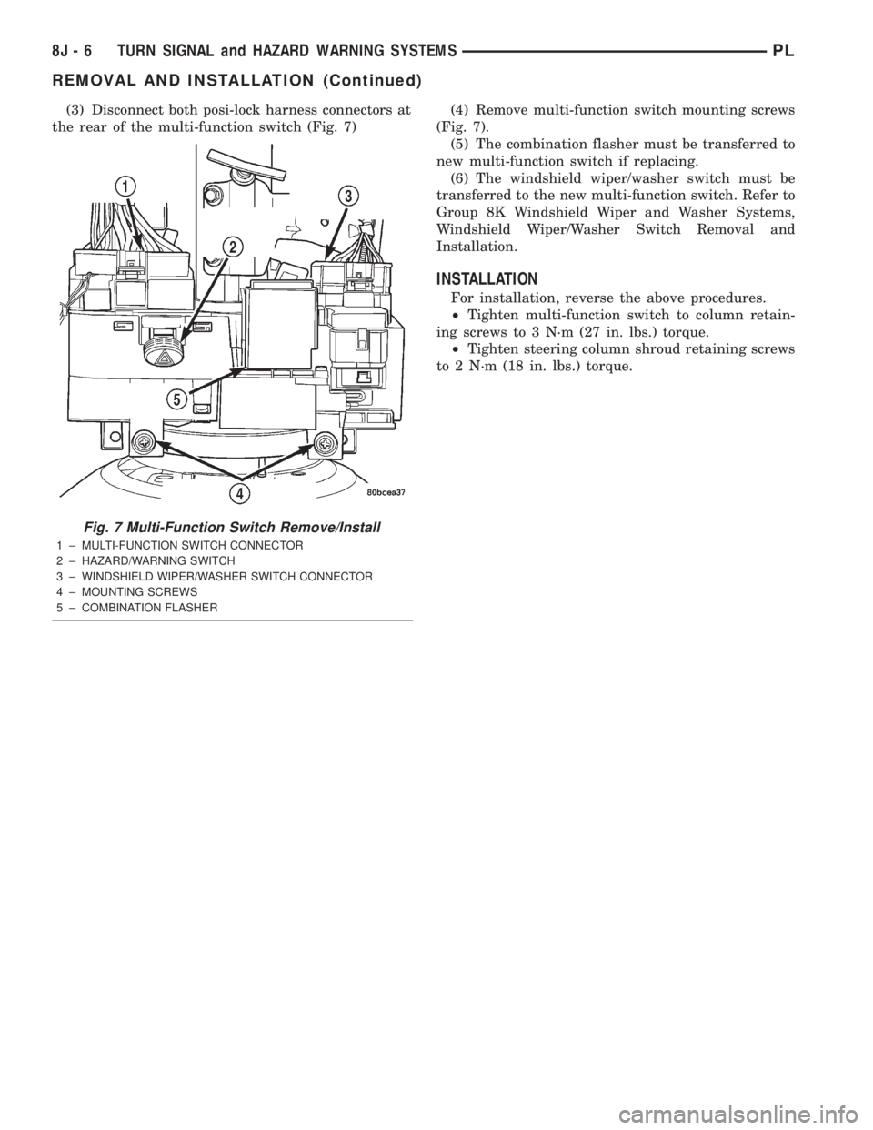
(3) Disconnect both posi-lock harness connectors at
the rear of the multi-function switch (Fig. 7)(4) Remove multi-function switch mounting screws
(Fig. 7).
(5) The combination flasher must be transferred to
new multi-function switch if replacing.
(6) The windshield wiper/washer switch must be
transferred to the new multi-function switch. Refer to
Group 8K Windshield Wiper and Washer Systems,
Windshield Wiper/Washer Switch Removal and
Installation.
INSTALLATION
For installation, reverse the above procedures.
²Tighten multi-function switch to column retain-
ing screws to 3 N´m (27 in. lbs.) torque.
²Tighten steering column shroud retaining screws
to 2 N´m (18 in. lbs.) torque.
Fig. 7 Multi-Function Switch Remove/Install
1 ± MULTI-FUNCTION SWITCH CONNECTOR
2 ± HAZARD/WARNING SWITCH
3 ± WINDSHIELD WIPER/WASHER SWITCH CONNECTOR
4 ± MOUNTING SCREWS
5 ± COMBINATION FLASHER
8J - 6 TURN SIGNAL and HAZARD WARNING SYSTEMSPL
REMOVAL AND INSTALLATION (Continued)
Page 298 of 1285
WINDSHIELD WIPER and WASHER SYSTEMS
TABLE OF CONTENTS
page page
WINDSHIELD WIPER SYSTEM................ 1WINDSHIELD WASHER SYSTEM.............. 8
WINDSHIELD WIPER SYSTEM
TABLE OF CONTENTS
page page
GENERAL INFORMATION
INTRODUCTION..........................1
DESCRIPTION AND OPERATION
WIPER BLADES...........................1
DIAGNOSIS AND TESTING
WINDSHIELD WIPER CONDITIONS............2
WINDSHIELD WIPER MOTOR................3
WINDSHIELD WIPER/WASHER SWITCH........5
REMOVAL AND INSTALLATION
WINDSHIELD WIPER ARM(S)................5WINDSHIELD WIPER BLADE(S)..............5
WINDSHIELD WIPER BLADE ELEMENT........5
WINDSHIELD WIPER LINKAGE...............5
WINDSHIELD WIPER MODULE...............6
WINDSHIELD WIPER MOTOR................6
WINDSHIELD WIPER/WASHER SWITCH........6
CLEANING AND INSPECTION
WINDSHIELD WIPER BLADE(S)..............6
ADJUSTMENTS
WINDSHIELD WIPER ARM(S)................6
GENERAL INFORMATION
INTRODUCTION
WARNING: ON VEHICLES EQUIPPED WITH AIR-
BAGS, REFER TO GROUP 8M, PASSIVE
RESTRAINT SYSTEMS FOR STEERING WHEEL
REMOVAL AND INSTALLATION.
The windshield wipers will only operate with the
ignition switch in the ACCESSORY or IGNITION
RUN position. The wiper circuit is protected against
over loads by a fuse in the fuse block and a circuit
breaker within the wiper motor. This protects the cir-
cuitry of the wiper system and the vehicle. The wiper
motor has permanent magnet fields.
The intermittent wiper system, in addition to low
and high speed, has a delay mode and a pulse wipe
mode. The delay mode has a range of 1 to 15 seconds.
Pulse wipe is accomplished by momentarily moving
the stalk lever into the WASH position while the
wiper switch is in either OFF or DELAY position.
The wiper blades then sweep once or twice and
return to the previous wiper switch mode, OFF or
DELAY.The intermittent wiper function is integral to the
wiper switch. All electronics and relay are inside the
switch assembly.
The wiper system completes the wipe cycle when
the switch is turned OFF. The blades park in the
lowest portion of the wipe pattern.
The wiper switch also includes the MIST feature
which provides a single wipe when actuated.
DESCRIPTION AND OPERATION
WIPER BLADES
Wiper blades, exposed to the weather for a long
period of time, tend to lose their wiping effectiveness.
Periodic cleaning of the wiper blade is suggested to
remove the accumulation of salt and road film. The
wiper blades, arms, and windshield should be
cleaned with a sponge or cloth and a mild detergent
or nonabrasive cleaner. If the blades continue to
streak or smear, they should be replaced. The right
and left wipers are different blade lengths. The
driver side length is 550 mm and the passenger side
length is 475 mm. The blades should not be inter-
changed.
PLWINDSHIELD WIPER and WASHER SYSTEMS 8K - 1
Page 299 of 1285
DIAGNOSIS AND TESTING
WINDSHIELD WIPER CONDITIONS
WARNING: ON VEHICLES EQUIPPED WITH AIR-
BAGS, REFER TO GROUP 8M, PASSIVE
RESTRAINT SYSTEMS FOR STEERING WHEEL
REMOVAL AND INSTALLATION.
The following is a list of general wiper motor sys-
tem problems, the tests that are to be performed to
locate the faulty part, and the corrective action to be
taken.
Whatever the problem, disconnect motor wire har-
ness and clean the terminals, then connect motor
wire harness and test.
Refer to Group 8W Wiring Diagrams for circuit
information and connector call-outs.
MOTOR WILL NOT OPERATE IN SOME OR ALL
SWITCH POSITIONS
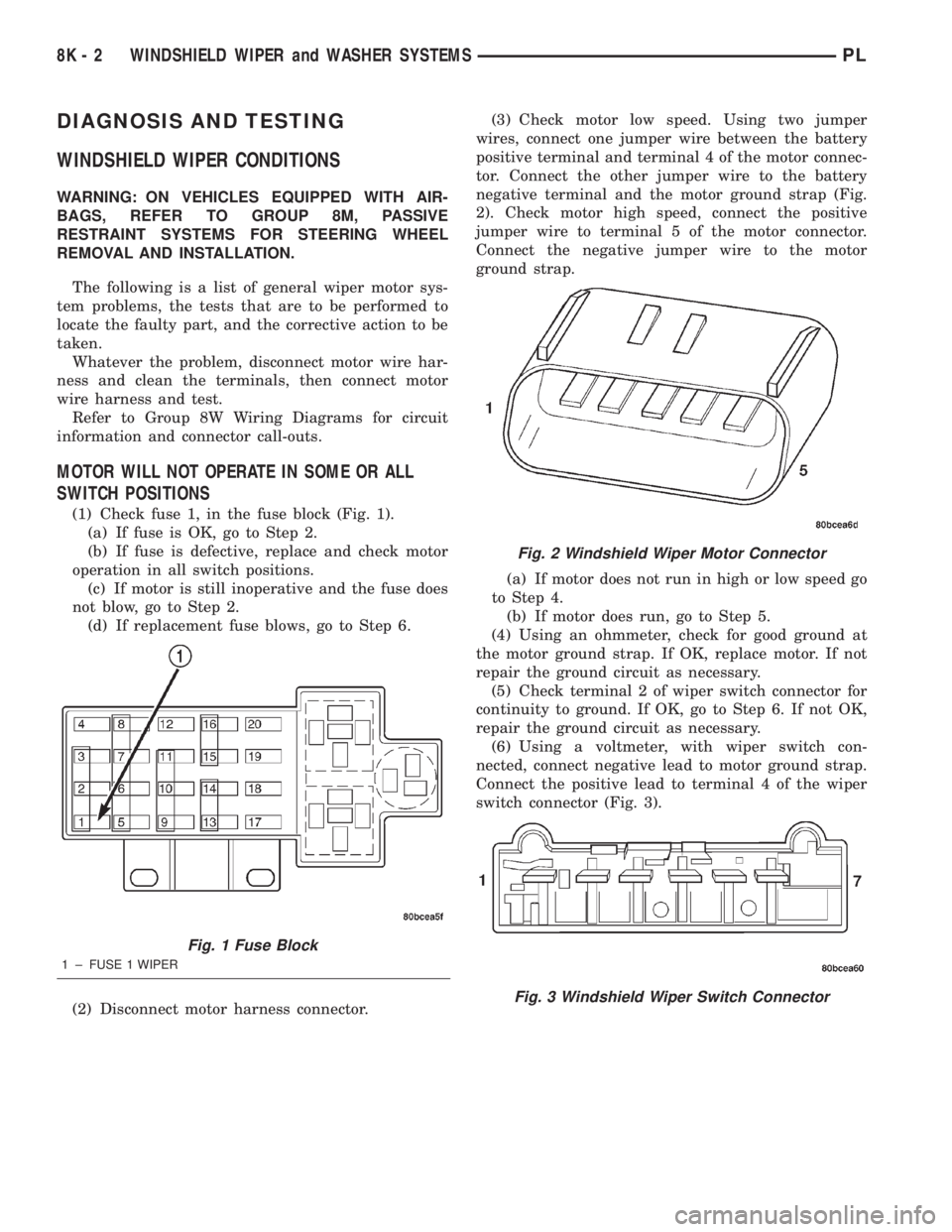
(1) Check fuse 1, in the fuse block (Fig. 1).
(a) If fuse is OK, go to Step 2.
(b) If fuse is defective, replace and check motor
operation in all switch positions.
(c) If motor is still inoperative and the fuse does
not blow, go to Step 2.
(d) If replacement fuse blows, go to Step 6.
(2) Disconnect motor harness connector.(3) Check motor low speed. Using two jumper
wires, connect one jumper wire between the battery
positive terminal and terminal 4 of the motor connec-
tor. Connect the other jumper wire to the battery
negative terminal and the motor ground strap (Fig.
2). Check motor high speed, connect the positive
jumper wire to terminal 5 of the motor connector.
Connect the negative jumper wire to the motor
ground strap.
(a) If motor does not run in high or low speed go
to Step 4.
(b) If motor does run, go to Step 5.
(4) Using an ohmmeter, check for good ground at
the motor ground strap. If OK, replace motor. If not
repair the ground circuit as necessary.
(5) Check terminal 2 of wiper switch connector for
continuity to ground. If OK, go to Step 6. If not OK,
repair the ground circuit as necessary.
(6) Using a voltmeter, with wiper switch con-
nected, connect negative lead to motor ground strap.
Connect the positive lead to terminal 4 of the wiper
switch connector (Fig. 3).
Fig. 1 Fuse Block
1 ± FUSE 1 WIPER
Fig. 2 Windshield Wiper Motor Connector
Fig. 3 Windshield Wiper Switch Connector
8K - 2 WINDSHIELD WIPER and WASHER SYSTEMSPL
Page 300 of 1285
(a) If no voltage, repair wiring as necessary. If
OK, go to Step b.
(b) Check wiper switch low speed. Connect volt-
meter positive lead to terminal 6 of the wiper
switch connector. Move wiper stalk to LOW posi-
tion. If no voltage, replace switch.
(c) Check wiper switch high speed, connect volt-
meter positive lead to terminal 5 of the wiper
switch connector. Move wiper stalk to HIGH posi-
tion. If no voltage, replace switch.
(7) Disconnect motor connector and replace fuse 1
in fuse block.
(a) If fuse does not blow, replace motor.
(b) If fuse blows, disconnect wiper switch and
replace fuse.
(c) If fuse does not blow, replace switch.
(d) If fuse blows, repair wiring as necessary.
MOTOR OPERATES SLOWLY AT ALL SPEEDS
(1) Remove wiper arms and cowl screen. Discon-
nect motor linkage from motor. Connect an ammeter
between battery positive terminal and terminal 4 of
the motor connector. Turn wiper motor on and check
ampere reading.
If motor runs and ammeter reading is more than 6
amps, go to Step 2. If less than 6 amps, go to Step 3.
When replacing drive link nut tighten to 11 to 12
N´m (98 to 106 in. lbs.) torque.
(2) Using an ohmmeter, check the high and low
circuits for a short to ground. Refer to Group 8W,
Wiring Diagrams.
(3) Check to see if wiper linkage or pivots are
binding or caught.
WIPERS RUN AT HIGH SPEED WITH SWITCH IN
LOW SPEED POSITION OR WIPERS RUN AT LOW
SPEED WITH SWITCH IN HIGH SPEED POSITION.
(1) Check for crossed wires in the motor pigtail
wire connector. Refer to Group 8W, Wiring Diagrams.
(2) Check for crossed wires in harness connector
from wiper switch to motor.
(3) If OK, replace wiper switch.
WIPERS WILL OPERATE CONTINUOUSLY WITH
THE SWITCH IN THE INTERMITTENT POSITION -
WHEN WIPER SWITCH IS TURNED OFF, WIPERS
STOP WHEREVER THEY ARE WITHOUT
RETURNING TO PARK POSITION.
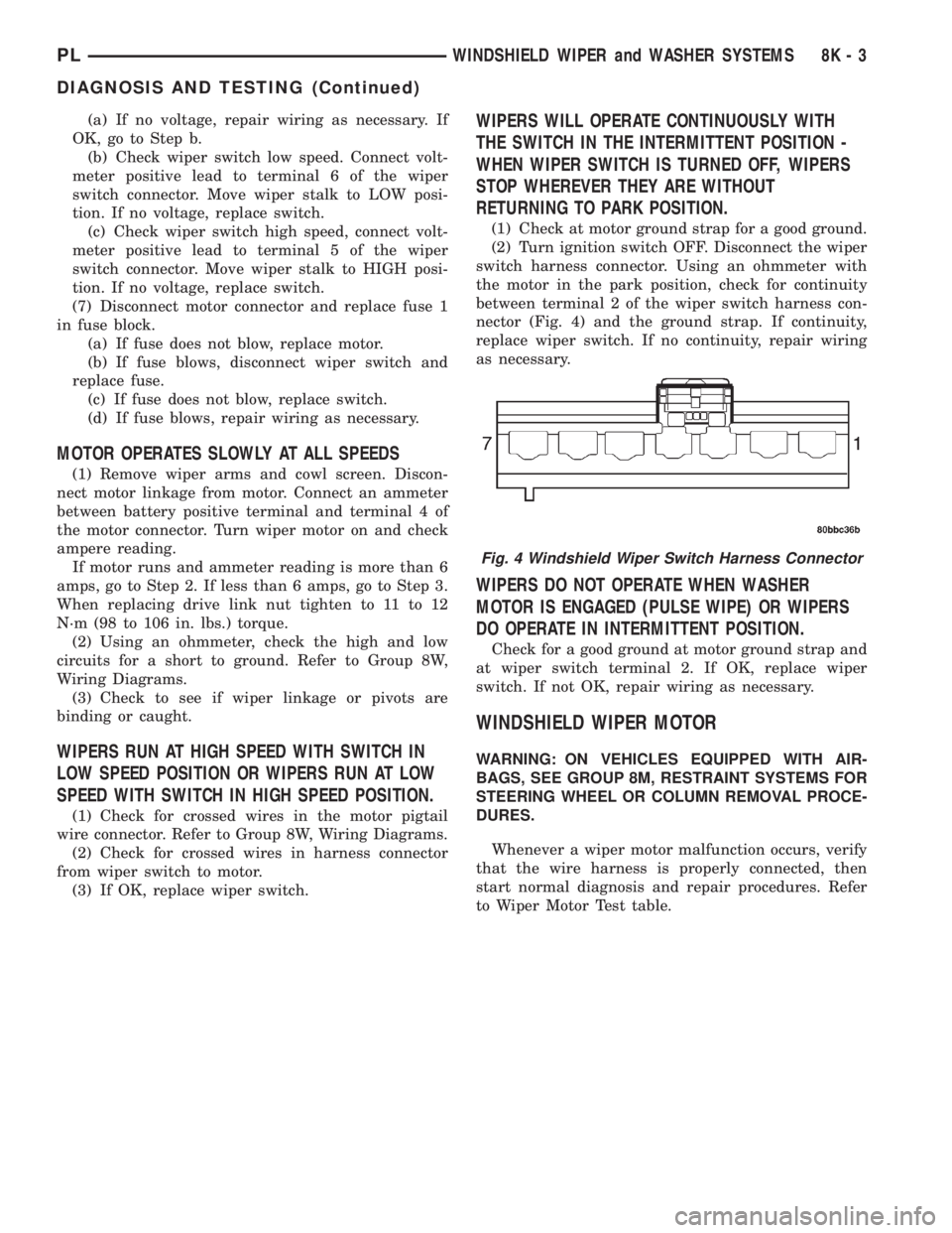
(1) Check at motor ground strap for a good ground.
(2) Turn ignition switch OFF. Disconnect the wiper
switch harness connector. Using an ohmmeter with
the motor in the park position, check for continuity
between terminal 2 of the wiper switch harness con-
nector (Fig. 4) and the ground strap. If continuity,
replace wiper switch. If no continuity, repair wiring
as necessary.
WIPERS DO NOT OPERATE WHEN WASHER
MOTOR IS ENGAGED (PULSE WIPE) OR WIPERS
DO OPERATE IN INTERMITTENT POSITION.
Check for a good ground at motor ground strap and
at wiper switch terminal 2. If OK, replace wiper
switch. If not OK, repair wiring as necessary.
WINDSHIELD WIPER MOTOR
WARNING: ON VEHICLES EQUIPPED WITH AIR-
BAGS, SEE GROUP 8M, RESTRAINT SYSTEMS FOR
STEERING WHEEL OR COLUMN REMOVAL PROCE-
DURES.
Whenever a wiper motor malfunction occurs, verify
that the wire harness is properly connected, then
start normal diagnosis and repair procedures. Refer
to Wiper Motor Test table.
Fig. 4 Windshield Wiper Switch Harness Connector
PLWINDSHIELD WIPER and WASHER SYSTEMS 8K - 3
DIAGNOSIS AND TESTING (Continued)