DODGE NEON 2000 Service Repair Manual
Manufacturer: DODGE, Model Year: 2000, Model line: NEON, Model: DODGE NEON 2000Pages: 1285, PDF Size: 29.42 MB
Page 381 of 1285
(6) If window does not move, check to make sure
that it is free to move.
(7) It is necessary that the window be free to slide
up and down in the glass channels. If the window is
not free to move up and down, the window lift motor
will not be able to move the glass.
(8) To determine if the glass is free, disconnect the
regulator from the glass lift plate and slide the win-
dow up and down by hand.
REMOVAL AND INSTALLATION
WINDOW SWITCH
REMOVAL
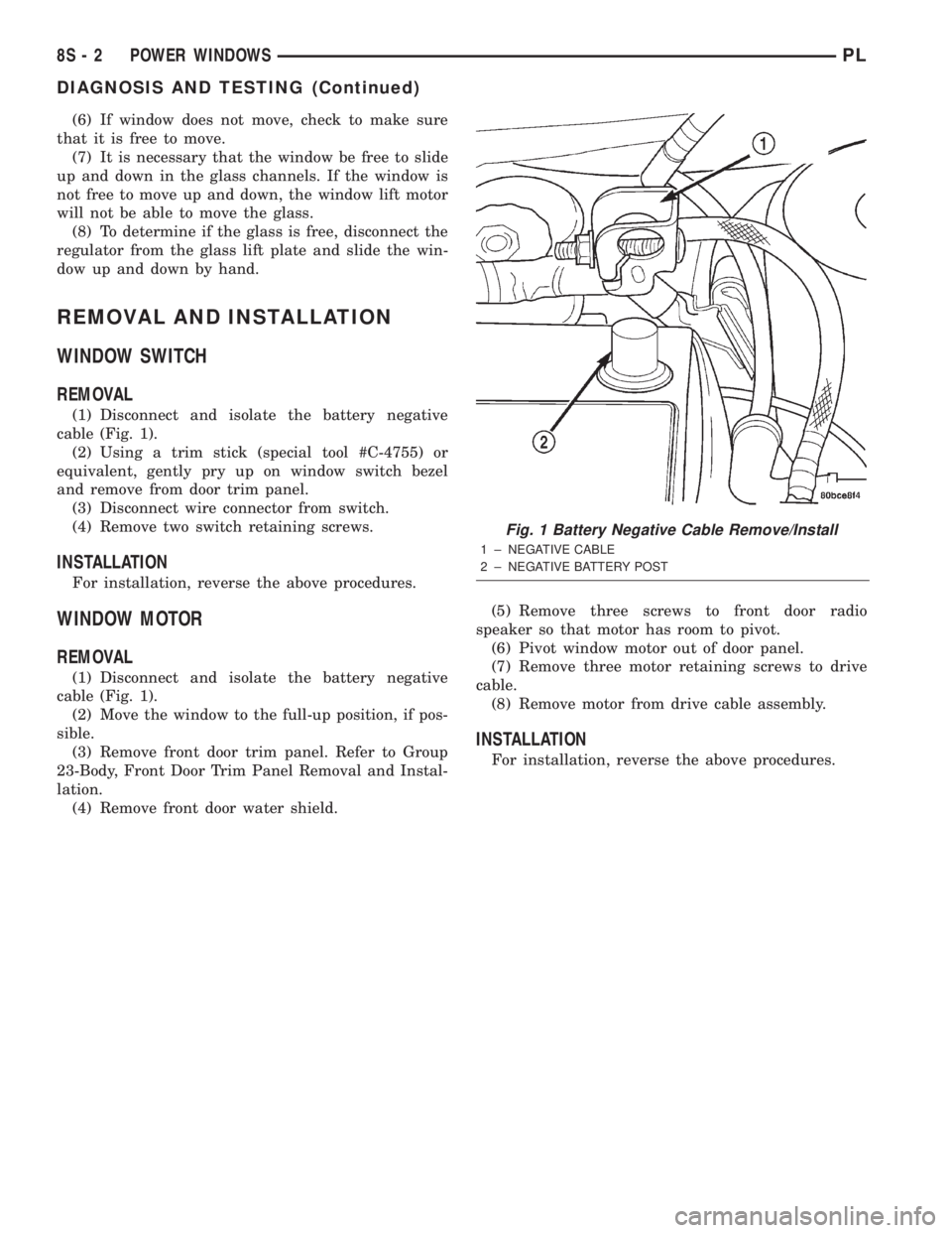
(1) Disconnect and isolate the battery negative
cable (Fig. 1).
(2) Using a trim stick (special tool #C-4755) or
equivalent, gently pry up on window switch bezel
and remove from door trim panel.
(3) Disconnect wire connector from switch.
(4) Remove two switch retaining screws.
INSTALLATION
For installation, reverse the above procedures.
WINDOW MOTOR
REMOVAL
(1) Disconnect and isolate the battery negative
cable (Fig. 1).
(2) Move the window to the full-up position, if pos-
sible.
(3) Remove front door trim panel. Refer to Group
23-Body, Front Door Trim Panel Removal and Instal-
lation.
(4) Remove front door water shield.(5) Remove three screws to front door radio
speaker so that motor has room to pivot.
(6) Pivot window motor out of door panel.
(7) Remove three motor retaining screws to drive
cable.
(8) Remove motor from drive cable assembly.
INSTALLATION
For installation, reverse the above procedures.
Fig. 1 Battery Negative Cable Remove/Install
1 ± NEGATIVE CABLE
2 ± NEGATIVE BATTERY POST
8S - 2 POWER WINDOWSPL
DIAGNOSIS AND TESTING (Continued)
Page 382 of 1285
POWER MIRRORS
TABLE OF CONTENTS
page page
DESCRIPTION AND OPERATION
INTRODUCTION..........................1
DIAGNOSIS AND TESTING
MIRROR SWITCH TEST....................1
POWER MIRROR MOTOR..................2
REMOVAL AND INSTALLATION
INSIDE MIRROR/READING LAMPS
ASSEMBLY.............................2INSIDE MIRROR/READING LAMPS
BULB/LENS............................3
MIRROR SWITCH.........................3
POWER MIRROR ASSEMBLY................3
DESCRIPTION AND OPERATION
INTRODUCTION
Electrically operated power mirrors are available
on all car lines. The mirrors are controlled by a sin-
gle switch assembly located on the driver's door trim
panel. The push button rocker switch uses L (left)
and R (right) for mirror selection and a button to
push for the desired direction of mirror movement.
The motors which operate the mirrors are part of
the mirror assembly and cannot be replaced sepa-
rately.
The Ignition Off Draw fuse is included in the
power mirror circuity and should be checked if the
mirrors are inoperative.
DIAGNOSIS AND TESTING
MIRROR SWITCH TEST
(1) Remove power mirror switch from mounting
position. Refer to Mirror Switch Removal and Instal-
lation in this section.
(2) Using an ohmmeter, test for continuity between
the terminals of the switch as shown in the Mirror
Switch Continuity table.
(3) If test results are not obtained as shown in the
Mirror Switch Continuity table, replace the switch.
Refer to Group 8W-Wiring Diagrams for Connector
Pin-Outs and Circuit Diagrams.
PLPOWER MIRRORS 8T - 1
Page 383 of 1285
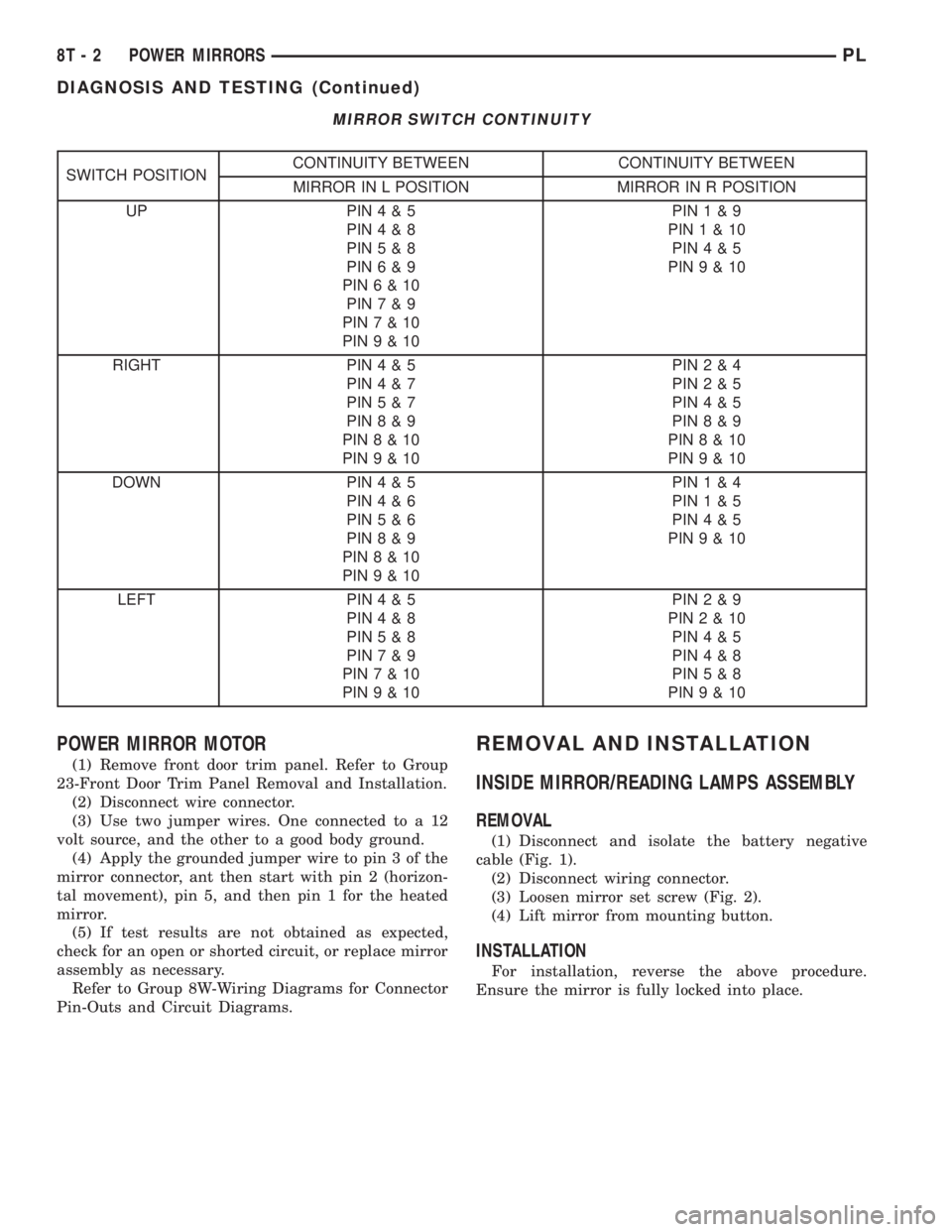
MIRROR SWITCH CONTINUITY
SWITCH POSITIONCONTINUITY BETWEEN CONTINUITY BETWEEN
MIRROR IN L POSITION MIRROR IN R POSITION
UP PIN4&5
PIN4&8
PIN5&8
PIN6&9
PIN6&10
PIN7&9
PIN7&10
PIN9&10PIN1&9
PIN1&10
PIN4&5
PIN9&10
RIGHT PIN4&5
PIN4&7
PIN5&7
PIN8&9
PIN8&10
PIN9&10PIN2&4
PIN2&5
PIN4&5
PIN8&9
PIN8&10
PIN9&10
DOWN PIN4&5
PIN4&6
PIN5&6
PIN8&9
PIN8&10
PIN9&10PIN1&4
PIN1&5
PIN4&5
PIN9&10
LEFT PIN4&5
PIN4&8
PIN5&8
PIN7&9
PIN7&10
PIN9&10PIN2&9
PIN2&10
PIN4&5
PIN4&8
PIN5&8
PIN9&10
POWER MIRROR MOTOR
(1) Remove front door trim panel. Refer to Group
23-Front Door Trim Panel Removal and Installation.
(2) Disconnect wire connector.
(3) Use two jumper wires. One connected to a 12
volt source, and the other to a good body ground.
(4) Apply the grounded jumper wire to pin 3 of the
mirror connector, ant then start with pin 2 (horizon-
tal movement), pin 5, and then pin 1 for the heated
mirror.
(5) If test results are not obtained as expected,
check for an open or shorted circuit, or replace mirror
assembly as necessary.
Refer to Group 8W-Wiring Diagrams for Connector
Pin-Outs and Circuit Diagrams.
REMOVAL AND INSTALLATION
INSIDE MIRROR/READING LAMPS ASSEMBLY
REMOVAL
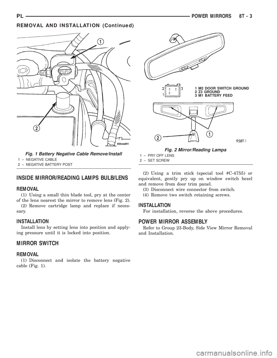
(1) Disconnect and isolate the battery negative
cable (Fig. 1).
(2) Disconnect wiring connector.
(3) Loosen mirror set screw (Fig. 2).
(4) Lift mirror from mounting button.
INSTALLATION
For installation, reverse the above procedure.
Ensure the mirror is fully locked into place.
8T - 2 POWER MIRRORSPL
DIAGNOSIS AND TESTING (Continued)
Page 384 of 1285
INSIDE MIRROR/READING LAMPS BULB/LENS
REMOVAL
(1) Using a small thin blade tool, pry at the center
of the lens nearest the mirror to remove lens (Fig. 2).
(2) Remove cartridge lamp and replace if neces-
sary.
INSTALLATION
Install lens by setting lens into position and apply-
ing pressure until it is locked into position.
MIRROR SWITCH
REMOVAL
(1) Disconnect and isolate the battery negative
cable (Fig. 1).(2) Using a trim stick (special tool #C-4755) or
equivalent, gently pry up on window switch bezel
and remove from door trim panel.
(3) Disconnect wire connector from switch.
(4) Remove two switch retaining screws.
INSTALLATION
For installation, reverse the above procedures.
POWER MIRROR ASSEMBLY
Refer to Group 23-Body, Side View Mirror Removal
and Installation.
Fig. 1 Battery Negative Cable Remove/Install
1 ± NEGATIVE CABLE
2 ± NEGATIVE BATTERY POST
Fig. 2 Mirror/Reading Lamps
1 ± PRY OFF LENS
2 ± SET SCREW1 M2 DOOR SWITCH GROUND
2 Z3 GROUND
3 M1 BATTERY FEED
PLPOWER MIRRORS 8T - 3
REMOVAL AND INSTALLATION (Continued)
Page 385 of 1285

Page 386 of 1285
POWER MIRRORS
TABLE OF CONTENTS
page page
GENERAL INFORMATION
INTRODUCTION..........................1
DIAGNOSIS AND TESTING
POWER FOLD AWAY MIRROR SWITCH TEST...1POWER FOLD AWAY MIRROR MOTOR........1
REMOVAL AND INSTALLATION
POWER FOLD-AWAY MIRROR SWITCH.......1
POWER FOLD-AWAY MIRROR...............2
GENERAL INFORMATION
INTRODUCTION
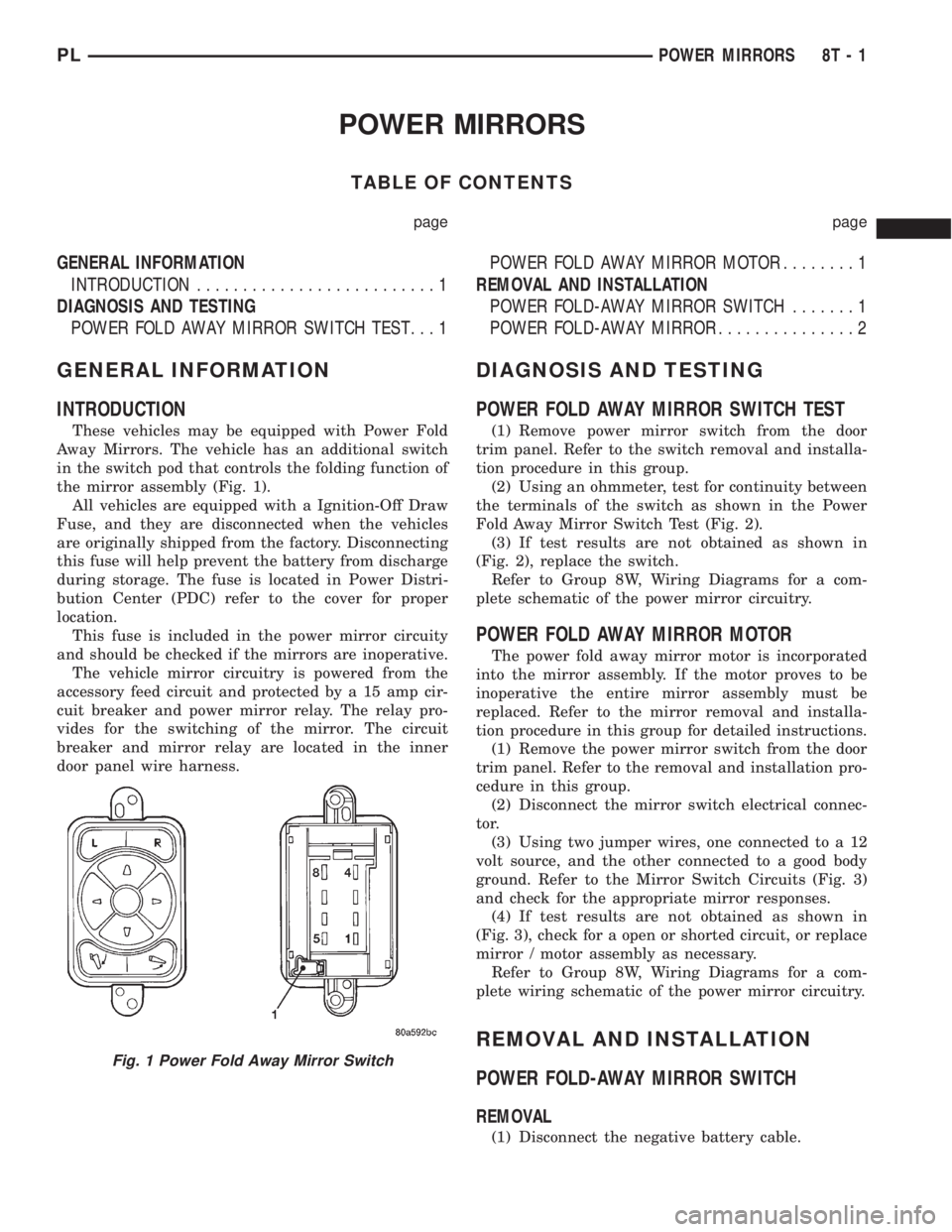
These vehicles may be equipped with Power Fold
Away Mirrors. The vehicle has an additional switch
in the switch pod that controls the folding function of
the mirror assembly (Fig. 1).
All vehicles are equipped with a Ignition-Off Draw
Fuse, and they are disconnected when the vehicles
are originally shipped from the factory. Disconnecting
this fuse will help prevent the battery from discharge
during storage. The fuse is located in Power Distri-
bution Center (PDC) refer to the cover for proper
location.
This fuse is included in the power mirror circuity
and should be checked if the mirrors are inoperative.
The vehicle mirror circuitry is powered from the
accessory feed circuit and protected by a 15 amp cir-
cuit breaker and power mirror relay. The relay pro-
vides for the switching of the mirror. The circuit
breaker and mirror relay are located in the inner
door panel wire harness.
DIAGNOSIS AND TESTING
POWER FOLD AWAY MIRROR SWITCH TEST
(1) Remove power mirror switch from the door
trim panel. Refer to the switch removal and installa-
tion procedure in this group.
(2) Using an ohmmeter, test for continuity between
the terminals of the switch as shown in the Power
Fold Away Mirror Switch Test (Fig. 2).
(3) If test results are not obtained as shown in
(Fig. 2), replace the switch.
Refer to Group 8W, Wiring Diagrams for a com-
plete schematic of the power mirror circuitry.
POWER FOLD AWAY MIRROR MOTOR
The power fold away mirror motor is incorporated
into the mirror assembly. If the motor proves to be
inoperative the entire mirror assembly must be
replaced. Refer to the mirror removal and installa-
tion procedure in this group for detailed instructions.
(1) Remove the power mirror switch from the door
trim panel. Refer to the removal and installation pro-
cedure in this group.
(2) Disconnect the mirror switch electrical connec-
tor.
(3) Using two jumper wires, one connected to a 12
volt source, and the other connected to a good body
ground. Refer to the Mirror Switch Circuits (Fig. 3)
and check for the appropriate mirror responses.
(4) If test results are not obtained as shown in
(Fig. 3), check for a open or shorted circuit, or replace
mirror / motor assembly as necessary.
Refer to Group 8W, Wiring Diagrams for a com-
plete wiring schematic of the power mirror circuitry.
REMOVAL AND INSTALLATION
POWER FOLD-AWAY MIRROR SWITCH
REMOVAL
(1) Disconnect the negative battery cable.
Fig. 1 Power Fold Away Mirror Switch
PLPOWER MIRRORS 8T - 1
Page 387 of 1285
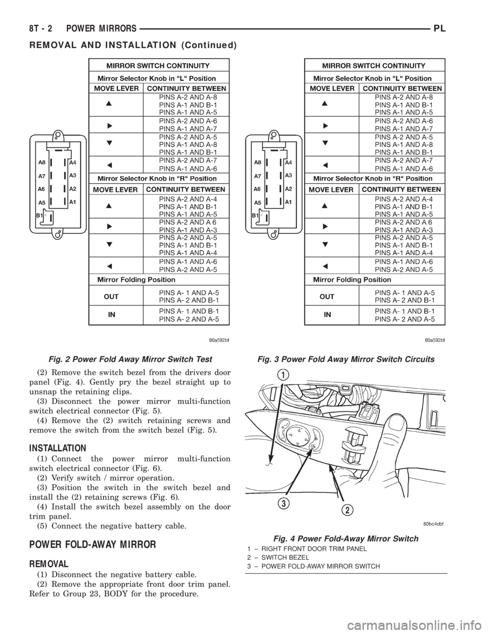
(2) Remove the switch bezel from the drivers door
panel (Fig. 4). Gently pry the bezel straight up to
unsnap the retaining clips.
(3) Disconnect the power mirror multi-function
switch electrical connector (Fig. 5).
(4) Remove the (2) switch retaining screws and
remove the switch from the switch bezel (Fig. 5).
INSTALLATION
(1) Connect the power mirror multi-function
switch electrical connector (Fig. 6).
(2) Verify switch / mirror operation.
(3) Position the switch in the switch bezel and
install the (2) retaining screws (Fig. 6).
(4) Install the switch bezel assembly on the door
trim panel.
(5) Connect the negative battery cable.
POWER FOLD-AWAY MIRROR
REMOVAL
(1) Disconnect the negative battery cable.
(2) Remove the appropriate front door trim panel.
Refer to Group 23, BODY for the procedure.
Fig. 2 Power Fold Away Mirror Switch TestFig. 3 Power Fold Away Mirror Switch Circuits
Fig. 4 Power Fold-Away Mirror Switch
1 ± RIGHT FRONT DOOR TRIM PANEL
2 ± SWITCH BEZEL
3 ± POWER FOLD-AWAY MIRROR SWITCH
8T - 2 POWER MIRRORSPL
REMOVAL AND INSTALLATION (Continued)
Page 388 of 1285
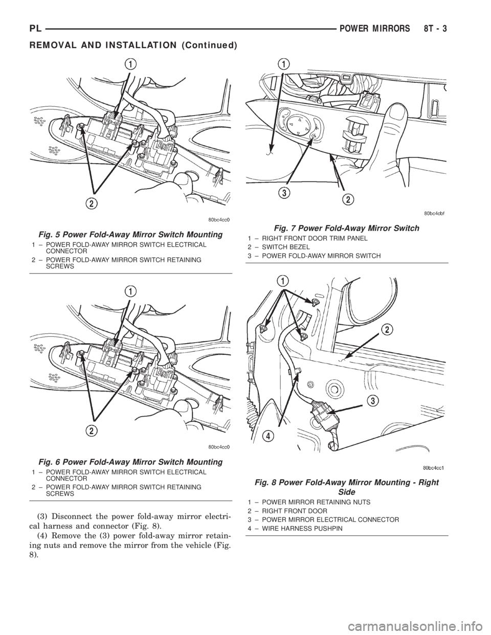
(3) Disconnect the power fold-away mirror electri-
cal harness and connector (Fig. 8).
(4) Remove the (3) power fold-away mirror retain-
ing nuts and remove the mirror from the vehicle (Fig.
8).
Fig. 5 Power Fold-Away Mirror Switch Mounting
1 ± POWER FOLD-AWAY MIRROR SWITCH ELECTRICAL
CONNECTOR
2 ± POWER FOLD-AWAY MIRROR SWITCH RETAINING
SCREWS
Fig. 6 Power Fold-Away Mirror Switch Mounting
1 ± POWER FOLD-AWAY MIRROR SWITCH ELECTRICAL
CONNECTOR
2 ± POWER FOLD-AWAY MIRROR SWITCH RETAINING
SCREWS
Fig. 7 Power Fold-Away Mirror Switch
1 ± RIGHT FRONT DOOR TRIM PANEL
2 ± SWITCH BEZEL
3 ± POWER FOLD-AWAY MIRROR SWITCH
Fig. 8 Power Fold-Away Mirror Mounting - Right
Side
1 ± POWER MIRROR RETAINING NUTS
2 ± RIGHT FRONT DOOR
3 ± POWER MIRROR ELECTRICAL CONNECTOR
4 ± WIRE HARNESS PUSHPIN
PLPOWER MIRRORS 8T - 3
REMOVAL AND INSTALLATION (Continued)
Page 389 of 1285
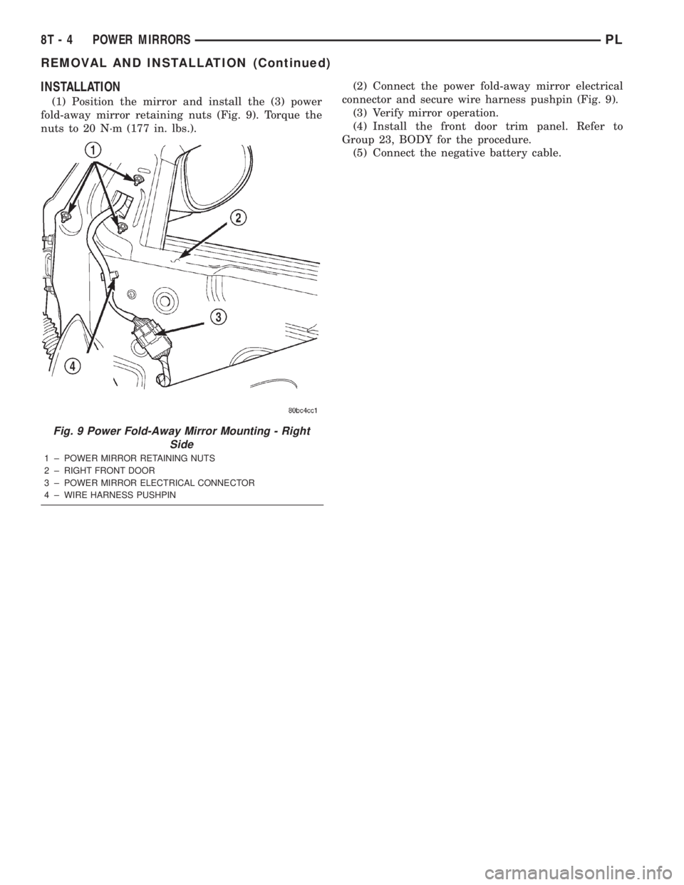
INSTALLATION
(1) Position the mirror and install the (3) power
fold-away mirror retaining nuts (Fig. 9). Torque the
nuts to 20 N´m (177 in. lbs.).(2) Connect the power fold-away mirror electrical
connector and secure wire harness pushpin (Fig. 9).
(3) Verify mirror operation.
(4) Install the front door trim panel. Refer to
Group 23, BODY for the procedure.
(5) Connect the negative battery cable.
Fig. 9 Power Fold-Away Mirror Mounting - Right
Side
1 ± POWER MIRROR RETAINING NUTS
2 ± RIGHT FRONT DOOR
3 ± POWER MIRROR ELECTRICAL CONNECTOR
4 ± WIRE HARNESS PUSHPIN
8T - 4 POWER MIRRORSPL
REMOVAL AND INSTALLATION (Continued)
Page 390 of 1285
CHIME WARNING/REMINDER SYSTEM
TABLE OF CONTENTS
page page
DESCRIPTION AND OPERATION
INTRODUCTION..........................1
DIAGNOSIS AND TESTING
FASTEN SEAT BELTS......................1
HEADLAMPS LEFT ON.....................1
KEY LEFT IN IGNITION SWITCH.............1CHIME SYSTEM CONDITIONS...............1
REMOVAL AND INSTALLATION
CHIME..................................2
SEAT BELT BUCKLE.......................2
HEADLAMP SWITCH......................2
KEY-IN SWITCH..........................2
DESCRIPTION AND OPERATION
INTRODUCTION
WARNING: ON VEHICLES EQUIPPED WITH AN AIR-
BAG, REFER TO THE AIRBAG PORTION OF THIS
SECTION FOR STEERING WHEEL OR SWITCH
REMOVAL AND INSTALLATION PROCEDURES.
The seat belt reminder system uses both visual
and audible signals. A combined seat belt and key
reminder chime with a red light on the instrument
panel.
The system will always illuminate the seat belt
reminder lamp for four to eight seconds when the
ignition switch is turned to the ON position. The
CHIME will sound during the same time interval if
the driver's seat belt is not fastened. Passenger belts
are not connected to the system.
The chime will activate if the drivers door is
opened and:
²The key is in the ignition switch, with the igni-
tion switch in either the OFF or accessory (ACC)
position.
²The head lamps are ON.
The chime is integral to the instrument cluster.
DIAGNOSIS AND TESTING
FASTEN SEAT BELTS
To test the fasten seat belts function, turn the igni-
tion switch to the ON position with the driver's seat
belt unbuckled and fully retracted. The seat belt
warning lamp should light for four to eight seconds
and the tone should sound three to five times.
If the lamp does not light, check the connection at
the seat belt retractor and the LED in the instru-
ment cluster. Replace as necessary.
HEADLAMPS LEFT ON
These are the conditions that have to be met for
the headlamps on, chime function to work:
²Headlamps ON.
²Driver's door open.
²Key removed from the ignition switch.
Chime should sound until headlamps are turned
off or driver's door is closed.
If these conditions are met and there is still a
problem with the system, replace the instrument
cluster. Refer to Group 8E-Instrument Panel and
Systems, Instrument Cluster Removal and Installa-
tion.
KEY LEFT IN IGNITION SWITCH
To test the key left in ignition function, insert key
into the ignition and open the driver's door. Chime
should sound until key is removed from ignition or
driver's door is closed.
If these conditions are met and there is still a
problem with the system, replace the instrument
cluster. Refer to Group 8E-Instrument Panel and
Systems, Instrument Cluster Removal and Installa-
tion.
CHIME SYSTEM CONDITIONS
NO TONE WHEN IGNITION SWITCH IS TURNED ON
AND DRIVERS SEAT BELT IS UNBUCKLED
(1) Using an ohmmeter, with the seat belt fully
retracted, check for continuity to ground at Pin 25 of
the cluster harness connector. If OK, go to step 2. If
not OK, repair as necessary.
(2) Using voltmeter, check for battery feed at Pin
21 of the cluster harness connector. Check for igni-
tion feed at Pin 15 of the cluster harness connector.
If not OK, repair as necessary.
PLCHIME WARNING/REMINDER SYSTEM 8U - 1