Engine torque spec DODGE RAM 1500 1998 2.G Workshop Manual
[x] Cancel search | Manufacturer: DODGE, Model Year: 1998, Model line: RAM 1500, Model: DODGE RAM 1500 1998 2.GPages: 2627
Page 1494 of 2627
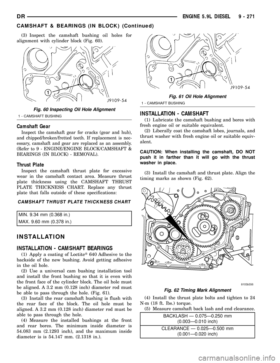
(3) Inspect the camshaft bushing oil holes for
alignment with cylinder block (Fig. 60).
Camshaft Gear
Inspect the camshaft gear for cracks (gear and hub),
and chipped/broken/fretted teeth. If replacement is nec-
essary, camshaft and gear are replaced as an assembly.
(Refer to 9 - ENGINE/ENGINE BLOCK/CAMSHAFT &
BEARINGS (IN BLOCK) - REMOVAL).
Thrust Plate
Inspect the camshaft thrust plate for excessive
wear in the camshaft contact area. Measure thrust
plate thickness using the CAMSHAFT THRUST
PLATE THICKNESS CHART. Replace any thrust
plate that falls outside of these specifications:
CAMSHAFT THRUST PLATE THICKNESS CHART
MIN. 9.34 mm (0.368 in.)
MAX. 9.60 mm (0.378 in.)
INSTALLATION
INSTALLATION - CAMSHAFT BEARINGS
(1) Apply a coating of Loctitet640 Adhesive to the
backside of the new bushing. Avoid getting adhesive
in the oil hole.
(2) Use a universal cam bushing installation tool
and install the front bushing so that it is even with
the front face of the cylinder block. The oil hole must
be aligned. A 3.2 mm (0.128 inch) diameter rod must
be able to pass through the hole. (Fig. 61).
(3) Install the rear camshaft bushing is flush with
the rear face of the block. The oil hole must be
aligned. A 3.2 mm (0.128 inch) diameter rod must be
able to pass through the hole.
(4) Measure the installed bushings at the front
and rear bores. The minimum inside diameter is
54.083 mm (2.1293 inch), and the maximum inside
diameter is is 54.147 mm. (2.1318 in.).
INSTALLATION - CAMSHAFT
(1) Lubricate the camshaft bushing and bores with
fresh engine oil or suitable equivalent.
(2) Liberally coat the camshaft lobes, journals, and
thrust washer with fresh engine oil or suitable equiv-
alent.
CAUTION: When installing the camshaft, DO NOT
push it in farther than it will go with the thrust
washer in place.
(3) Install the camshaft and thrust plate. Align the
timing marks as shown (Fig. 62).
(4) Install the thrust plate bolts and tighten to 24
N´m (18 ft. lbs.) torque.
(5) Measure camshaft back lash and end clearance.
BACKLASH Ð 0.075Ð0.250 mm
(0.003Ð0.010 inch)
CLEARANCE Ð 0.025Ð0.500 mm
(0.001Ð0.020 inch)
Fig. 60 Inspecting Oil Hole Alignment
1 - CAMSHAFT BUSHING
Fig. 61 Oil Hole Alignment
1 - CAMSHAFT BUSHING
Fig. 62 Timing Mark Alignment
DRENGINE 5.9L DIESEL 9 - 271
CAMSHAFT & BEARINGS (IN BLOCK) (Continued)
Page 1497 of 2627
CRANKSHAFT MAIN
BEARINGS
STANDARD PROCEDURE - MAIN BEARING
CLEARANCE
Inspect the main bearing bores for damage or
abnormal wear.
(1) Remove bearings and measure main bearing
bore diameter after torquing main bearing cap bolts
to 176 Nm (130 ft. lbs.).
(2) Install the crankshaft main bearings and mea-
sure main bearing bore diameter with the main bolts
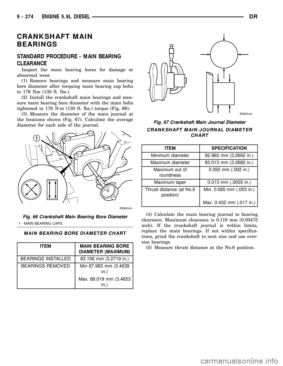
tightened to 176 N´m (130 ft. lbs.) torque (Fig. 66).
(3) Measure the diameter of the main journal at
the locations shown (Fig. 67). Calculate the average
diameter for each side of the journal.
MAIN BEARING BORE DIAMETER CHART
ITEM MAIN BEARING BORE
DIAMETER (MAXIMUM)
BEARINGS INSTALLED 83.106 mm (3.2719 in.)
BEARINGS REMOVED Min 87.983 mm (3.4639
in.)
Max. 88.019 mm (3.4653
in.)
CRANKSHAFT MAIN JOURNAL DIAMETER
CHART
ITEM SPECIFICATION
Minimum diameter 82.962 mm (3.2662 in.)
Maximum diameter 83.013 mm (3.2682 in.)
Maximum out of
roundness0.050 mm (.002 in.)
Maximum taper 0.013 mm (.0005 in.)
Thrust distance (at No.6
position)Min. 0.065 mm (.003 in.)
Max. 0.432 mm (.017 in.)
(4) Calculate the main bearing journal to bearing
clearance. Maximum clearance is 0.119 mm (0.00475
inch). If the crankshaft journal is within limits,
replace the main bearings. If not within specifica-
tions, grind the crankshaft to next size and use over-
size bearings.
(5) Measure thrust distance at the No.6 position.
Fig. 66 Crankshaft Main Bearing Bore Diameter
1 - MAIN BEARING CAPS
Fig. 67 Crankshaft Main Journal Diameter
9 - 274 ENGINE 5.9L DIESELDR
Page 1499 of 2627
(6) Apply a bead of MopartSilicone Rubber Adhe-
sive Sealant or equivalent to the gear housing cover
sealing surface.
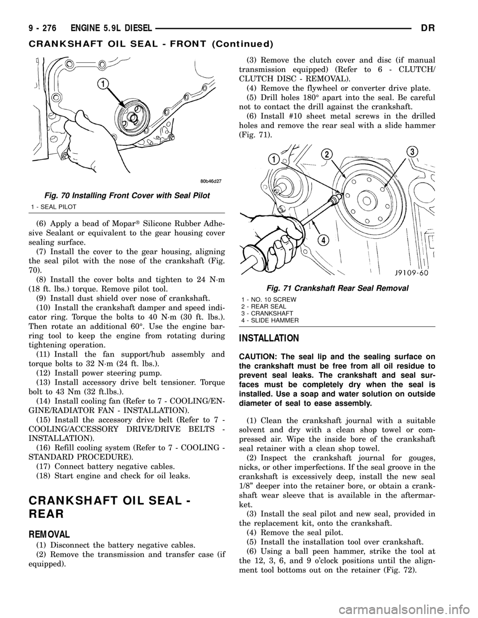
(7) Install the cover to the gear housing, aligning
the seal pilot with the nose of the crankshaft (Fig.
70).
(8) Install the cover bolts and tighten to 24 N´m
(18 ft. lbs.) torque. Remove pilot tool.
(9) Install dust shield over nose of crankshaft.
(10) Install the crankshaft damper and speed indi-
cator ring. Torque the bolts to 40 N´m (30 ft. lbs.).
Then rotate an additional 60É. Use the engine bar-
ring tool to keep the engine from rotating during
tightening operation.
(11) Install the fan support/hub assembly and
torque bolts to 32 N´m (24 ft. lbs.).
(12) Install power steering pump.
(13) Install accessory drive belt tensioner. Torque
bolt to 43 Nm (32 ft.lbs.).
(14) Install cooling fan (Refer to 7 - COOLING/EN-
GINE/RADIATOR FAN - INSTALLATION).
(15) Install the accessory drive belt (Refer to 7 -
COOLING/ACCESSORY DRIVE/DRIVE BELTS -
INSTALLATION).
(16) Refill cooling system (Refer to 7 - COOLING -
STANDARD PROCEDURE).
(17) Connect battery negative cables.
(18) Start engine and check for oil leaks.
CRANKSHAFT OIL SEAL -
REAR
REMOVAL
(1) Disconnect the battery negative cables.
(2) Remove the transmission and transfer case (if
equipped).(3) Remove the clutch cover and disc (if manual
transmission equipped) (Refer to 6 - CLUTCH/
CLUTCH DISC - REMOVAL).
(4) Remove the flywheel or converter drive plate.
(5) Drill holes 180É apart into the seal. Be careful
not to contact the drill against the crankshaft.
(6) Install #10 sheet metal screws in the drilled
holes and remove the rear seal with a slide hammer
(Fig. 71).
INSTALLATION
CAUTION: The seal lip and the sealing surface on
the crankshaft must be free from all oil residue to
prevent seal leaks. The crankshaft and seal sur-
faces must be completely dry when the seal is
installed. Use a soap and water solution on outside
diameter of seal to ease assembly.
(1) Clean the crankshaft journal with a suitable
solvent and dry with a clean shop towel or com-
pressed air. Wipe the inside bore of the crankshaft
seal retainer with a clean shop towel.
(2) Inspect the crankshaft journal for gouges,
nicks, or other imperfections. If the seal groove in the
crankshaft is excessively deep, install the new seal
1/8º deeper into the retainer bore, or obtain a crank-
shaft wear sleeve that is available in the aftermar-
ket.
(3) Install the seal pilot and new seal, provided in
the replacement kit, onto the crankshaft.
(4) Remove the seal pilot.
(5) Install the installation tool over crankshaft.
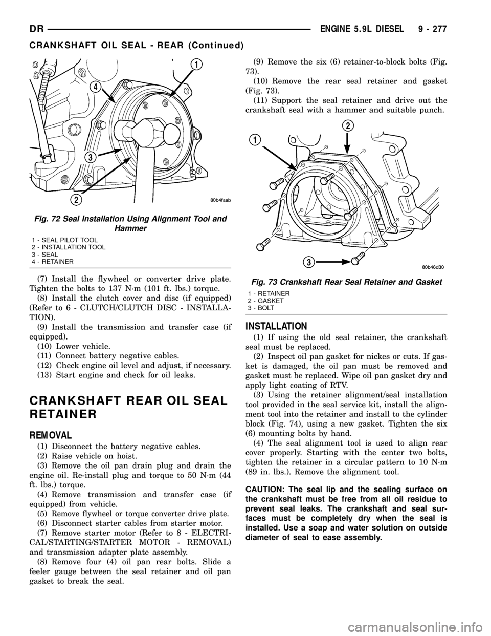
(6) Using a ball peen hammer, strike the tool at
the 12, 3, 6, and 9 o'clock positions until the align-
ment tool bottoms out on the retainer (Fig. 72).
Fig. 70 Installing Front Cover with Seal Pilot
1 - SEAL PILOT
Fig. 71 Crankshaft Rear Seal Removal
1 - NO. 10 SCREW
2 - REAR SEAL
3 - CRANKSHAFT
4 - SLIDE HAMMER
9 - 276 ENGINE 5.9L DIESELDR
CRANKSHAFT OIL SEAL - FRONT (Continued)
Page 1500 of 2627
(7) Install the flywheel or converter drive plate.
Tighten the bolts to 137 N´m (101 ft. lbs.) torque.
(8) Install the clutch cover and disc (if equipped)
(Refer to 6 - CLUTCH/CLUTCH DISC - INSTALLA-
TION).
(9) Install the transmission and transfer case (if
equipped).
(10) Lower vehicle.
(11) Connect battery negative cables.
(12) Check engine oil level and adjust, if necessary.
(13) Start engine and check for oil leaks.
CRANKSHAFT REAR OIL SEAL
RETAINER
REMOVAL
(1) Disconnect the battery negative cables.
(2) Raise vehicle on hoist.
(3) Remove the oil pan drain plug and drain the
engine oil. Re-install plug and torque to 50 N´m (44
ft. lbs.) torque.
(4) Remove transmission and transfer case (if
equipped) from vehicle.
(5)
Remove flywheel or torque converter drive plate.
(6) Disconnect starter cables from starter motor.
(7) Remove starter motor (Refer to 8 - ELECTRI-
CAL/STARTING/STARTER MOTOR - REMOVAL)
and transmission adapter plate assembly.
(8) Remove four (4) oil pan rear bolts. Slide a
feeler gauge between the seal retainer and oil pan
gasket to break the seal.(9) Remove the six (6) retainer-to-block bolts (Fig.
73).
(10) Remove the rear seal retainer and gasket
(Fig. 73).
(11) Support the seal retainer and drive out the
crankshaft seal with a hammer and suitable punch.
INSTALLATION
(1) If using the old seal retainer, the crankshaft
seal must be replaced.
(2) Inspect oil pan gasket for nickes or cuts. If gas-
ket is damaged, the oil pan must be removed and
gasket must be replaced. Wipe oil pan gasket dry and
apply light coating of RTV.
(3) Using the retainer alignment/seal installation
tool provided in the seal service kit, install the align-
ment tool into the retainer and install to the cylinder
block (Fig. 74), using a new gasket. Tighten the six
(6) mounting bolts by hand.
(4) The seal alignment tool is used to align rear
cover properly. Starting with the center two bolts,
tighten the retainer in a circular pattern to 10 N´m
(89 in. lbs.). Remove the alignment tool.
CAUTION: The seal lip and the sealing surface on
the crankshaft must be free from all oil residue to
prevent seal leaks. The crankshaft and seal sur-
faces must be completely dry when the seal is
installed. Use a soap and water solution on outside
diameter of seal to ease assembly.
Fig. 72 Seal Installation Using Alignment Tool and
Hammer
1 - SEAL PILOT TOOL
2 - INSTALLATION TOOL
3 - SEAL
4 - RETAINER
Fig. 73 Crankshaft Rear Seal Retainer and Gasket
1 - RETAINER
2 - GASKET
3 - BOLT
DRENGINE 5.9L DIESEL 9 - 277
CRANKSHAFT OIL SEAL - REAR (Continued)
Page 1509 of 2627
INSTALLATION
(1) Install speed indicator ring.
NOTE: The speed indicator ring is located over a
dowel pin.
(2) Install the crankshaft damper and bolts.
Tighten bolts to 40 N´m (30 ft. lbs.) torque, plus an
additional 60É.
NOTE: The damper must be installed so the hole is
located over the dowel pin.
(3) Install the accessory drive belt (Refer to 7 -
COOLING/ACCESSORY DRIVE/DRIVE BELTS -
INSTALLATION).
FRONT MOUNT
REMOVAL
(1) Disconnect the battery negative cables.
(2) Remove the viscous fan/drive assembly (Refer
to 7 - COOLING/ENGINE/RADIATOR FAN -
REMOVAL).
(3) Raise vehicle on hoist.
(4) Install engine support fixture tool# 8534 and
steel bracket tool # 8534A
(5) Loosen the thru-bolt and nut.
(6) Lift the engine SLIGHTLY and remove the
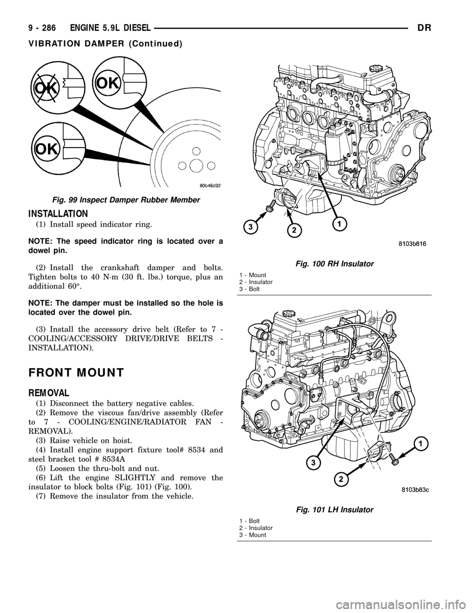
insulator to block bolts (Fig. 101) (Fig. 100).
(7) Remove the insulator from the vehicle.
Fig. 99 Inspect Damper Rubber Member
Fig. 100 RH Insulator
1 - Mount
2 - Insulator
3 - Bolt
Fig. 101 LH Insulator
1 - Bolt
2 - Insulator
3 - Mount
9 - 286 ENGINE 5.9L DIESELDR
VIBRATION DAMPER (Continued)
Page 1510 of 2627
INSTALLATION
(1) With engine raised SLIGHTLY, position the
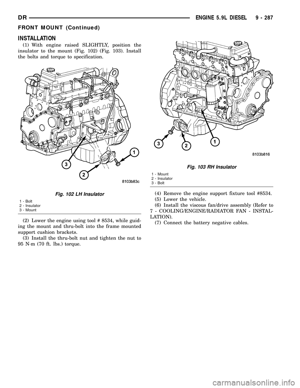
insulator to the mount (Fig. 102) (Fig. 103). Install
the bolts and torque to specification.
(2) Lower the engine using tool # 8534, while guid-
ing the mount and thru-bolt into the frame mounted
support cushion brackets.
(3) Install the thru-bolt nut and tighten the nut to
95 N´m (70 ft. lbs.) torque.(4) Remove the engine support fixture tool #8534.
(5) Lower the vehicle.
(6) Install the viscous fan/drive assembly (Refer to
7 - COOLING/ENGINE/RADIATOR FAN - INSTAL-
LATION).
(7) Connect the battery negative cables.
Fig. 102 LH Insulator
1 - Bolt
2 - Insulator
3 - Mount
Fig. 103 RH Insulator
1 - Mount
2 - Insulator
3 - Bolt
DRENGINE 5.9L DIESEL 9 - 287
FRONT MOUNT (Continued)
Page 1515 of 2627
OIL
STANDARD PROCEDURE
STANDARD PROCEDURE - ENGINE OIL LEVEL
CAUTION: Do not overfill crankcase with engine oil,
oil foaming and oil pressure loss can result.
To ensure proper lubrication of an engine, the
engine oil must be maintained at an acceptable level.
The acceptable oil level is in the SAFE RANGE on
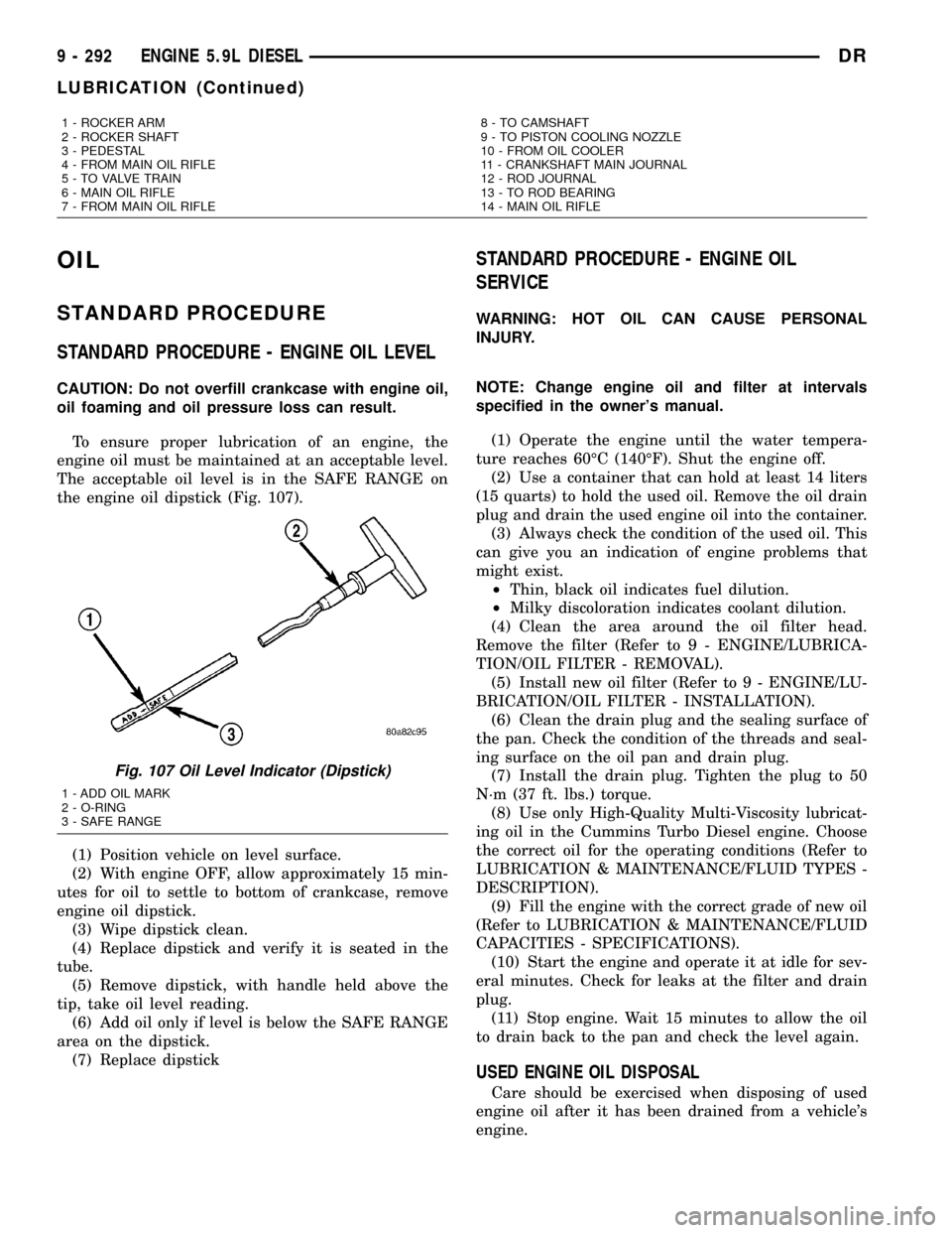
the engine oil dipstick (Fig. 107).
(1) Position vehicle on level surface.
(2) With engine OFF, allow approximately 15 min-
utes for oil to settle to bottom of crankcase, remove
engine oil dipstick.
(3) Wipe dipstick clean.
(4) Replace dipstick and verify it is seated in the
tube.
(5) Remove dipstick, with handle held above the
tip, take oil level reading.
(6) Add oil only if level is below the SAFE RANGE
area on the dipstick.
(7) Replace dipstick
STANDARD PROCEDURE - ENGINE OIL
SERVICE
WARNING: HOT OIL CAN CAUSE PERSONAL
INJURY.
NOTE: Change engine oil and filter at intervals
specified in the owner's manual.
(1) Operate the engine until the water tempera-
ture reaches 60ÉC (140ÉF). Shut the engine off.
(2) Use a container that can hold at least 14 liters
(15 quarts) to hold the used oil. Remove the oil drain
plug and drain the used engine oil into the container.
(3) Always check the condition of the used oil. This
can give you an indication of engine problems that
might exist.
²Thin, black oil indicates fuel dilution.
²Milky discoloration indicates coolant dilution.
(4) Clean the area around the oil filter head.
Remove the filter (Refer to 9 - ENGINE/LUBRICA-
TION/OIL FILTER - REMOVAL).
(5) Install new oil filter (Refer to 9 - ENGINE/LU-
BRICATION/OIL FILTER - INSTALLATION).
(6) Clean the drain plug and the sealing surface of
the pan. Check the condition of the threads and seal-
ing surface on the oil pan and drain plug.
(7) Install the drain plug. Tighten the plug to 50
N´m (37 ft. lbs.) torque.
(8) Use only High-Quality Multi-Viscosity lubricat-
ing oil in the Cummins Turbo Diesel engine. Choose
the correct oil for the operating conditions (Refer to
LUBRICATION & MAINTENANCE/FLUID TYPES -
DESCRIPTION).
(9) Fill the engine with the correct grade of new oil
(Refer to LUBRICATION & MAINTENANCE/FLUID
CAPACITIES - SPECIFICATIONS).
(10) Start the engine and operate it at idle for sev-
eral minutes. Check for leaks at the filter and drain
plug.
(11) Stop engine. Wait 15 minutes to allow the oil
to drain back to the pan and check the level again.
USED ENGINE OIL DISPOSAL
Care should be exercised when disposing of used
engine oil after it has been drained from a vehicle's
engine.
1 - ROCKER ARM
2 - ROCKER SHAFT
3 - PEDESTAL
4 - FROM MAIN OIL RIFLE
5 - TO VALVE TRAIN
6 - MAIN OIL RIFLE
7 - FROM MAIN OIL RIFLE8 - TO CAMSHAFT
9 - TO PISTON COOLING NOZZLE
10 - FROM OIL COOLER
11 - CRANKSHAFT MAIN JOURNAL
12 - ROD JOURNAL
13 - TO ROD BEARING
14 - MAIN OIL RIFLE
Fig. 107 Oil Level Indicator (Dipstick)
1 - ADD OIL MARK
2 - O-RING
3 - SAFE RANGE
9 - 292 ENGINE 5.9L DIESELDR
LUBRICATION (Continued)
Page 1516 of 2627
OIL COOLER & LINES
CLEANING
CLEANING AND INSPECTION
Clean the sealing surfaces.
Apply 483 kPa (70 psi) air pressure to the element
to check for leaks. If the element leaks, replace the
element.
OIL FILTER
REMOVAL
(1) Clean the area around the oil filter head.
Remove the filter from below using a cap-style filter
wrench.
(2) Clean the gasket surface of the filter head. The
filter canister O-Ring seal can stick on the filter
head. Make sure it is removed.
INSTALLATION
(1) Fill the oil filter element with clean oil before
installation. Use the same type oil that will be used
in the engine.
(2) Apply a light film of lubricating oil to the seal-
ing surface before installing the filter.
CAUTION: Mechanical over-tightening may distort
the threads or damage the filter element seal.
(3) Install the filter until it contacts the sealing
surface of the oil filter adapter. Tighten filter an
additional
1¤2turn.
OIL PAN
REMOVAL
(1) Disconnect the battery negative cables.
(2) Install engine support fixture # 8534.
(3) Raise vehicle on hoist.
(4) Disconnect starter cables from starter motor.
(5) Remove transmission and transfer case (if
equipped).
(6) Remove flywheel or flexplate.
(7) Remove starter motor (Refer to 8 - ELECTRI-
CAL/STARTING/STARTER MOTOR - REMOVAL)
and transmission adapter plate assembly.
WARNING: HOT OIL CAN CAUSE PERSONAL
INJURY.
(8) Drain the engine oil (Refer to 9 - ENGINE/LU-
BRICATION/OIL - STANDARD PROCEDURE).(9) Install the oil pan drain plug if sealing surface
is not damaged and tighten to 50 N´m (37 ft. lbs.)
torque.
(10) Remove oil pan bolts, break the pan to block
seal, and lower pan slightly and remove oil suction
tube fasteners.
(11) Remove oil pan and suction tube.
CLEANING
Remove all gasket material from the oil pan and
cylinder block sealing surfaces. Extra effort may be
required around T-joint areas. Clean oil pan and
flush suction tube with a suitable solvent.
INSPECTION
Inspect the oil pan, suction tube, and tube braces
for cracks and damage. Replace any defective compo-
nent. Inspect the oil drain plug and drain hole
threads. Inspect the oil pan sealing surface for
straightness. Repair any minor imperfections with a
ball-peen hammer. Do not attempt to repair an oil
pan by welding.
INSTALLATION
(1) Fill the T-joint between the pan rail/gear hous-
ing and pan rail/rear seal retainer with sealant. Use
MopartSilicone Rubber Adhesive Sealant or equiva-
lent.
(2) Place suction tube in oil pan and guide them
into place. Using a new tube to block gasket, install
and tighten the suction tube bolts by hand. Starting
with the oil pump inlet bolts, tighten the bolts to 24
N´m (18 ft. lbs.) torque. Tighten the remaining tube
brace bolts to 43 N´m (32 ft. lbs.) torque.
(3) Starting in the center and working outward,
tighten the oil pan bolts to 28 N´m (21 ft. lbs.)
torque.
(4) Install the flywheel housing assembly with the
starter motor attached and tighten bolts to 77 N´m
(57 ft. lbs.) torque.
(5) Connect starter motor cables.
(6) Install the flywheel or flexplate. Torque to 137
N´m (101 ft. lbs.).
(7) Install transmission and transfer case (if
equipped).
(8) Lower vehicle.
(9) Remove the engine support fixture # 8534.
(10) Install battery negative cables.
(11) Fill the crankcase with new engine oil.
(12) Start engine and check for leaks. Stop engine,
check oil level, and adjust, if necessary.
DRENGINE 5.9L DIESEL 9 - 293
Page 1517 of 2627
OIL PRESSURE RELIEF VALVE
REMOVAL
(1) Disconnect the battery negative cables.
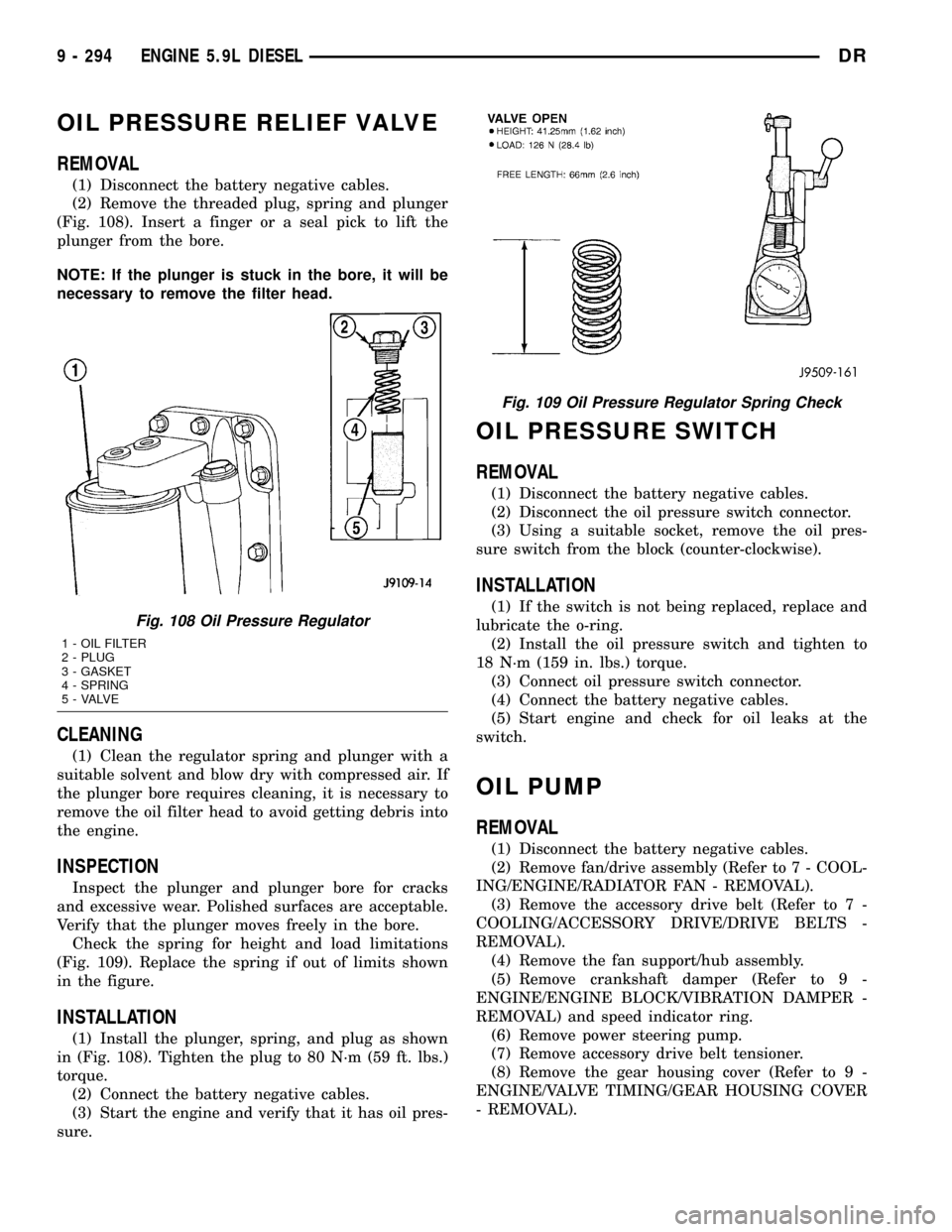
(2) Remove the threaded plug, spring and plunger
(Fig. 108). Insert a finger or a seal pick to lift the
plunger from the bore.
NOTE: If the plunger is stuck in the bore, it will be
necessary to remove the filter head.
CLEANING
(1) Clean the regulator spring and plunger with a
suitable solvent and blow dry with compressed air. If
the plunger bore requires cleaning, it is necessary to
remove the oil filter head to avoid getting debris into
the engine.
INSPECTION
Inspect the plunger and plunger bore for cracks
and excessive wear. Polished surfaces are acceptable.
Verify that the plunger moves freely in the bore.
Check the spring for height and load limitations
(Fig. 109). Replace the spring if out of limits shown
in the figure.
INSTALLATION
(1) Install the plunger, spring, and plug as shown
in (Fig. 108). Tighten the plug to 80 N´m (59 ft. lbs.)
torque.
(2) Connect the battery negative cables.
(3) Start the engine and verify that it has oil pres-
sure.
OIL PRESSURE SWITCH
REMOVAL
(1) Disconnect the battery negative cables.
(2) Disconnect the oil pressure switch connector.
(3) Using a suitable socket, remove the oil pres-
sure switch from the block (counter-clockwise).
INSTALLATION
(1) If the switch is not being replaced, replace and
lubricate the o-ring.
(2) Install the oil pressure switch and tighten to
18 N´m (159 in. lbs.) torque.
(3) Connect oil pressure switch connector.
(4) Connect the battery negative cables.
(5) Start engine and check for oil leaks at the
switch.
OIL PUMP
REMOVAL
(1) Disconnect the battery negative cables.
(2) Remove fan/drive assembly (Refer to 7 - COOL-
ING/ENGINE/RADIATOR FAN - REMOVAL).
(3) Remove the accessory drive belt (Refer to 7 -
COOLING/ACCESSORY DRIVE/DRIVE BELTS -
REMOVAL).
(4) Remove the fan support/hub assembly.
(5) Remove crankshaft damper (Refer to 9 -
ENGINE/ENGINE BLOCK/VIBRATION DAMPER -
REMOVAL) and speed indicator ring.
(6) Remove power steering pump.
(7) Remove accessory drive belt tensioner.
(8) Remove the gear housing cover (Refer to 9 -
ENGINE/VALVE TIMING/GEAR HOUSING COVER
- REMOVAL).
Fig. 108 Oil Pressure Regulator
1 - OIL FILTER
2 - PLUG
3 - GASKET
4 - SPRING
5 - VALVE
Fig. 109 Oil Pressure Regulator Spring Check
9 - 294 ENGINE 5.9L DIESELDR
Page 1521 of 2627
INSTALLATION
(1) Using a new gasket, install the intake manifold
cover.
(2) Install the cover-to-cylinder head bolts that do
not hold down the fuel rail. Tighten the bolts to 24
N´m (18 ft. lbs.) torque.
(3) Install the high pressure rail and fuel lines
(Refer to 14 - FUEL SYSTEM/FUEL DELIVERY/
FUEL LINES - INSTALLATION).
(4) Using two (2) new gaskets, install the intake
air grid heater and air inlet housing. Position the
ground cable and install and tighten the bolts to 24
N´m (18 ft. lbs.) torque.
(5) Connect the manifold air temperature/pressure
sensor connector.
(6) Install and tighten the air intake heater power
supply nuts to 14 N´m (120 in. lbs.) torque.
(7) Install the APPS bracket. Torque fasteners to
43 N´m (32ft lbs.) torque.
(8) Install oil dipstick tube support at fuel filter
housing.
(9) Install the engine oil dipstick tube and mount-
ing bolt.
(10) Position the charge air cooler outlet tube onto
the air inlet housing. Tighten the clamps to 11 N´m
(100 in. lbs.) torque.
(11) Attach the engine wire harness to the air inlet
housing at two locations.
(12) Prime the fuel system. Refer to the fuel prim-
ing procedure in Group 14, Fuel System.
(13) Connect the battery negative cables.
EXHAUST MANIFOLD
REMOVAL
(1) Disconnect the battery negative cables.
(2) Raise vehicle on hoist.
(3) Disconnect the exhaust pipe from the turbo-
charger elbow.
(4) Disconnect oil drain tube from turbocharger.
(5) Lower vehicle.
(6) Disconnect the turbocharger air inlet hose.
(7) Remove air cleaner assembly.
(8) Disconnect the turbocharger oil supply line.
(9) Disconnect the charge air cooler inlet pipe from
the turbocharger.
(10) Remove the turbocharger and gasket from the
exhaust manifold.
(11) Remove the cab heater return pipe nuts from
the exhaust manifold stud. Position the tube out of
the way.
(12) Remove heat shield.
(13) Remove exhaust manifold bolt lockplates.
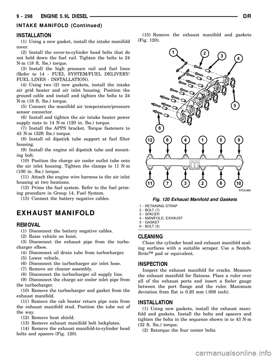
(14) Remove the exhaust manifold-to-cylinder head
bolts and spacers (Fig. 120).(15) Remove the exhaust manifold and gaskets
(Fig. 120).
CLEANING
Clean the cylinder head and exhaust manifold seal-
ing surfaces with a suitable scraper. Use a Scotch-
BriteŸ pad or equivalent.
INSPECTION
Inspect the exhaust manifold for cracks. Measure
the exhaust manifold for flatness. Place a ruler over
all of the exhaust ports and insert a feeler gauge
between the port flange and the ruler. Maximum
deviation from flat is 0.20 mm (.008 inch).
INSTALLATION
(1) Using new gaskets, install the exhaust mani-
fold and gaskets. Install the bolts and spacers and
tighten the bolts in the sequence shown in to 43 N´m
(32 ft. lbs.) torque.
(2) Retorque the four center bolts.
Fig. 120 Exhaust Manifold and Gaskets
1 - RETAINING STRAP
2 - BOLT (7)
3 - SPACER
4 - MANIFOLD, EXHAUST
5 - GASKET
6 - BOLT (5)
9 - 298 ENGINE 5.9L DIESELDR
INTAKE MANIFOLD (Continued)