Reverse DODGE RAM 1500 1998 2.G Owner's Manual
[x] Cancel search | Manufacturer: DODGE, Model Year: 1998, Model line: RAM 1500, Model: DODGE RAM 1500 1998 2.GPages: 2627
Page 617 of 2627

(5) Momentarily touch the Positive (+) jumper
probe to the other motor connector terminal.
When positive probe is connected the motor should
rotate in one direction to either move window up or
down. If window is all the way up or down the motor
will grunt and the inner door panel will flex when
actuated in that one direction.
(6) Reverse jumper probes at the motor connector
terminals and window should now move in opposite
direction. If window does not move or grunt, replace
the motor.
If window moved completely up or down, reverse
the jumper probes and cycle window to the opposite
position to verify full operation.
If motor grunts and does not move, verify that reg-
ulator is not binding.
WINDOW MOTOR
REMOVAL
The window motor is serviced with the window
regulator (Refer to 23 - BODY/DOOR - FRONT/WIN-
DOW REGULATOR - REMOVAL) or (Refer to 23 -
BODY/DOORS - REAR/WINDOW REGULATOR -
REMOVAL).
WINDOW SWITCH
DIAGNOSIS AND TESTING - WINDOW SWITCH
The Light-Emitting Diode (LED) illumination
lamps for all of the power window and lock switch
and bezel unit switch paddles receive battery current
through the power window circuit breaker in the
junction block. If all of the LEDs are inoperative in
both the power window and lock switch units and the
power windows are inoperative, (Refer to 8 - ELEC-
TRICAL/POWER WINDOWS - DIAGNOSIS AND
TESTING). If the power windows operate, but any or
all of the LEDs are inoperative, the power window
and lock switch units with the inoperative LED(s) is
faulty and must be replaced. For complete circuit dia-
grams, refer to the appropriate wiring information.
(1) Check the fuse in the Integrated Power Module
(IPM) and the circuit breaker located near the park
brake pedal. If OK, go to Step 2. If not OK, replace
the faulty fuse or circuit breaker.
(2) Turn the ignition switch to the On position.
Check for battery voltage at the fuse in the Inte-
grated Power Module (IPM). If OK, turn the ignition
switch to the Off position and go to Step 3. If not OK,
check circuit breaker and repair the circuit to the
ignition switch as required.
(3) Disconnect and isolate the battery negative
cable. Remove the power window switch unit fromthe door trim panel (passenger doors). The drivers
door switch is included with the Driver Door Module
(Refer to 8 - ELECTRICAL/POWER LOCKS/DOOR
MODULE - DIAGNOSIS AND TESTING) for service
procedures. Unplug the wire harness connector from
the switch unit.
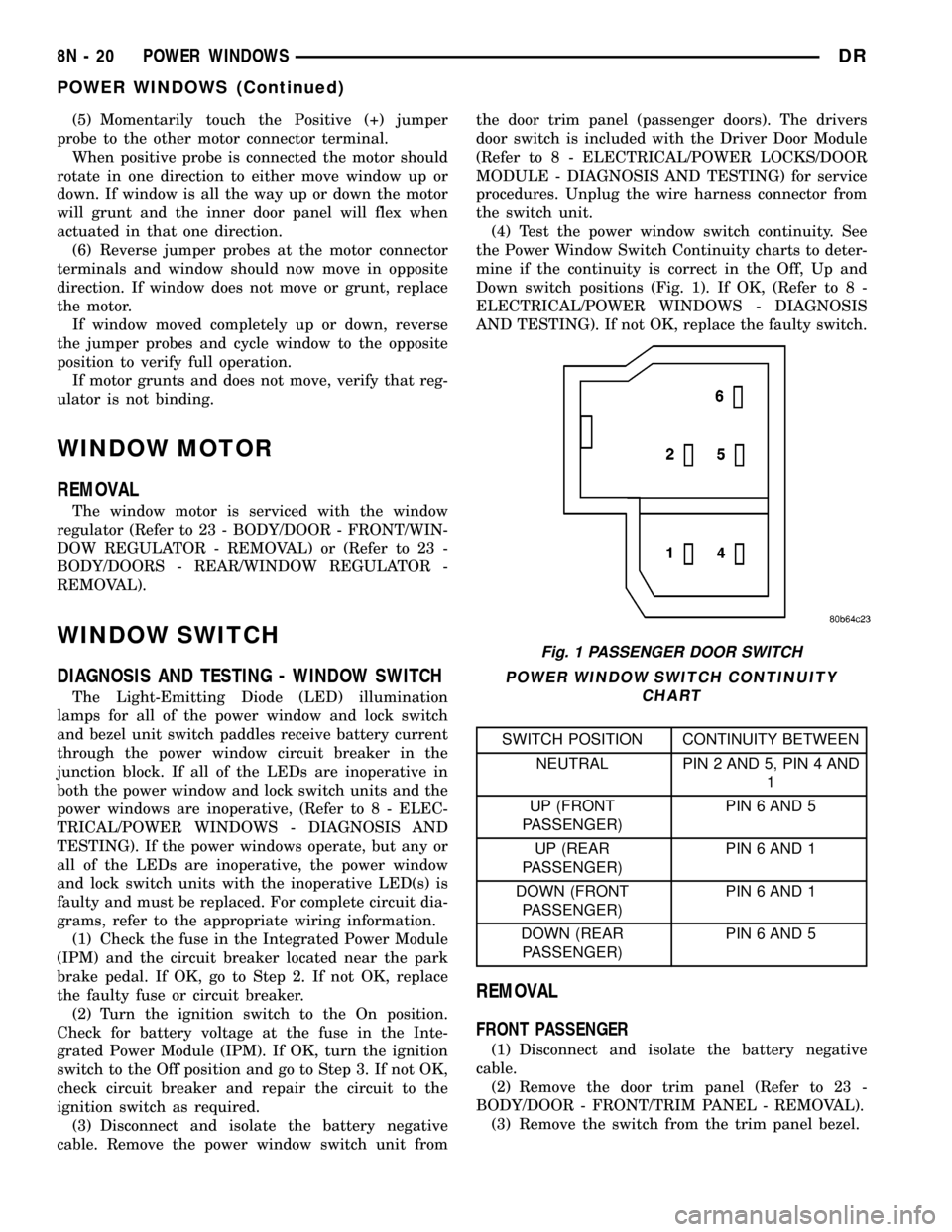
(4) Test the power window switch continuity. See
the Power Window Switch Continuity charts to deter-
mine if the continuity is correct in the Off, Up and
Down switch positions (Fig. 1). If OK, (Refer to 8 -
ELECTRICAL/POWER WINDOWS - DIAGNOSIS
AND TESTING). If not OK, replace the faulty switch.
POWER WINDOW SWITCH CONTINUITY
CHART
SWITCH POSITION CONTINUITY BETWEEN
NEUTRAL PIN 2 AND 5, PIN 4 AND
1
UP (FRONT
PASSENGER)PIN 6 AND 5
UP (REAR
PASSENGER)PIN 6 AND 1
DOWN (FRONT
PASSENGER)PIN 6 AND 1
DOWN (REAR
PASSENGER)PIN 6 AND 5
REMOVAL
FRONT PASSENGER
(1) Disconnect and isolate the battery negative
cable.
(2) Remove the door trim panel (Refer to 23 -
BODY/DOOR - FRONT/TRIM PANEL - REMOVAL).
(3) Remove the switch from the trim panel bezel.
Fig. 1 PASSENGER DOOR SWITCH
8N - 20 POWER WINDOWSDR
POWER WINDOWS (Continued)
Page 1056 of 2627

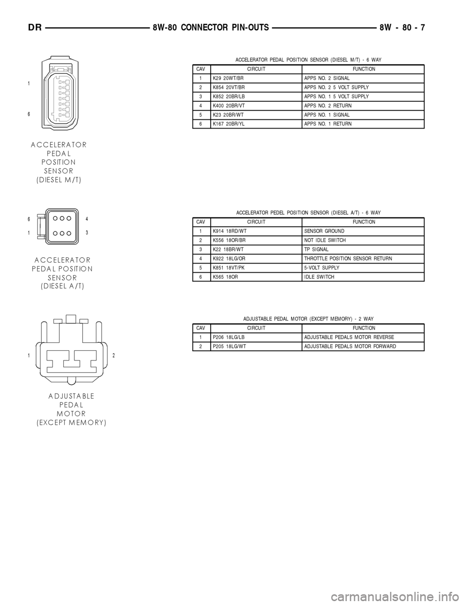
ACCELERATOR PEDAL POSITION SENSOR (DIESEL M/T)-6WAY
CAV CIRCUIT FUNCTION
1 K29 20WT/BR APPS NO. 2 SIGNAL
2 K854 20VT/BR APPS NO. 2 5 VOLT SUPPLY
3 K852 20BR/LB APPS NO. 1 5 VOLT SUPPLY
4 K400 20BR/VT APPS NO. 2 RETURN
5 K23 20BR/WT APPS NO. 1 SIGNAL
6 K167 20BR/YL APPS NO. 1 RETURN
ACCELERATOR PEDEL POSITION SENSOR (DIESEL A/T)-6WAY
CAV CIRCUIT FUNCTION
1 K914 18RD/WT SENSOR GROUND
2 K556 18OR/BR NOT IDLE SWITCH
3 K22 18BR/WT TP SIGNAL
4 K922 18LG/OR THROTTLE POSITION SENSOR RETURN
5 K851 18VT/PK 5-VOLT SUPPLY
6 K565 18OR IDLE SWITCH
ADJUSTABLE PEDAL MOTOR (EXCEPT MEMORY)-2WAY
CAV CIRCUIT FUNCTION
1 P206 18LG/LB ADJUSTABLE PEDALS MOTOR REVERSE
2 P205 18LG/WT ADJUSTABLE PEDALS MOTOR FORWARD
DR8W-80 CONNECTOR PIN-OUTS 8W - 80 - 7
Page 1057 of 2627

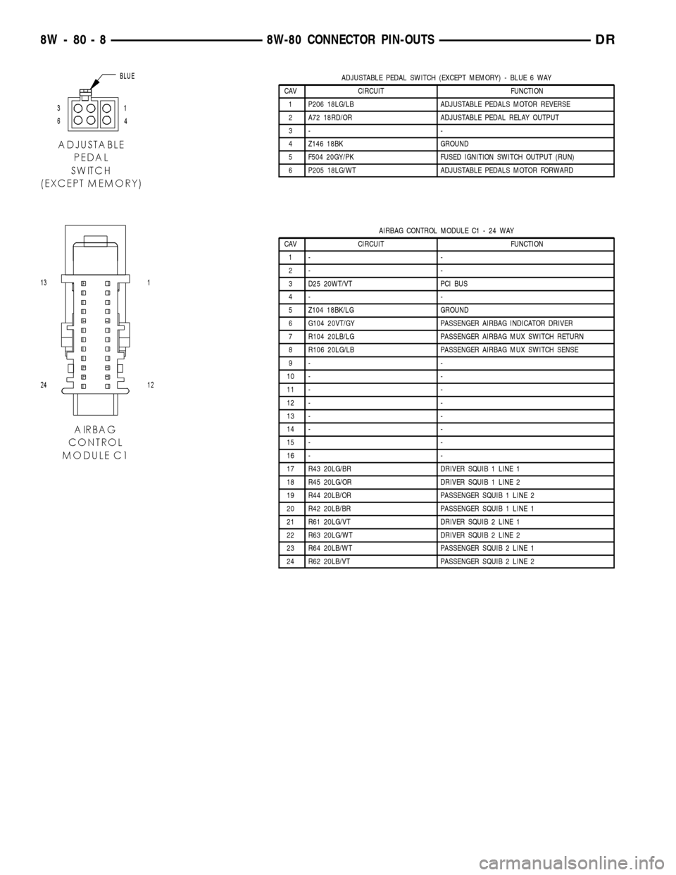
ADJUSTABLE PEDAL SWITCH (EXCEPT MEMORY) - BLUE 6 WAY
CAV CIRCUIT FUNCTION
1 P206 18LG/LB ADJUSTABLE PEDALS MOTOR REVERSE
2 A72 18RD/OR ADJUSTABLE PEDAL RELAY OUTPUT
3- -
4 Z146 18BK GROUND
5 F504 20GY/PK FUSED IGNITION SWITCH OUTPUT (RUN)
6 P205 18LG/WT ADJUSTABLE PEDALS MOTOR FORWARD
AIRBAG CONTROL MODULE C1 - 24 WAY
CAV CIRCUIT FUNCTION
1- -
2- -
3 D25 20WT/VT PCI BUS
4- -
5 Z104 18BK/LG GROUND
6 G104 20VT/GY PASSENGER AIRBAG INDICATOR DRIVER
7 R104 20LB/LG PASSENGER AIRBAG MUX SWITCH RETURN
8 R106 20LG/LB PASSENGER AIRBAG MUX SWITCH SENSE
9- -
10 - -
11 - -
12 - -
13 - -
14 - -
15 - -
16 - -
17 R43 20LG/BR DRIVER SQUIB 1 LINE 1
18 R45 20LG/OR DRIVER SQUIB 1 LINE 2
19 R44 20LB/OR PASSENGER SQUIB 1 LINE 2
20 R42 20LB/BR PASSENGER SQUIB 1 LINE 1
21 R61 20LG/VT DRIVER SQUIB 2 LINE 1
22 R63 20LG/WT DRIVER SQUIB 2 LINE 2
23 R64 20LB/WT PASSENGER SQUIB 2 LINE 1
24 R62 20LB/VT PASSENGER SQUIB 2 LINE 2
8W - 80 - 8 8W-80 CONNECTOR PIN-OUTSDR
Page 1140 of 2627

POWERTRAIN CONTROL MODULE C4 (NGC) - GREEN 38 WAY
CAV CIRCUIT FUNCTION
1 T60 18YL/GY OVERDRIVE SOLENOID CONTROL
2 T259 18YL/DG 4C SOLENOID CONTROL
3- -
4 T118 18DG MS SOLENOID CONTROL
5- -
6 T219 18YL/LG 2C SOLENOID CONTROL
7- -
8 T59 18YL/LB UNDERDRIVE SOLENOID CONTROL
9- -
10 T20 18DG/WT L/R SOLENOID CONTROL
11 T140 18YL/GY PRESSURE CONTROL SOLENOID CONTROL
12 Z908 18BK GROUND
13 Z977 18BK GROUND
14 Z904 18BK (A/T) GROUND
15 T1 18DG/LB TRS T1 SENSE
16 T3 18DG/DB TRS T3 SENSE
17 T6 18DG TOW/HAUL OVERDRIVE OFF SWITCH SENSE
18 T515 20YL/DB TRANSMISSION CONTROL RELAY CONTROL
19 T16 18YL/OR TRANSMISSION CONTROL RELAY OUTPUT
20 T48 18BR/YL 4C PRESSURE SWITCH SENSE
21 T29 18YL/WT UNDERDRIVE PRESSURE SWITCH SENSE
22 T9 18DG/TN OVERDRIVE PRESSURE SWITCH SENSE
23 - -
24 - -
25 - -
26 T4 18DG/LB TRS T2 SENSE
27 - -
28 T16 18YL/OR TRANSMISSION CONTROL RELAY OUTPUT
29 T50 18YL/TN LOW/REVERSE PRESSURE SWITCH SENSE
30 T147 18DG/YL 2C PRESSURE SWITCH SENSE
31 T38 18YL/BR LINE PRESSURE SENSOR SIGNAL
32 T14 18DG/BR OUTPUT SPEED SENSOR SIGNAL
33 T52 18DG/OR INPUT SPEED SENSOR SIGNAL
34 T13 18DG/VT SPEED SENSOR GROUND
35 T54 18DG/OR TRANSMISSION TEMPERATURE SENSOR SIGNAL
36 - -
37 T42 18DG/YL TRS T42 SENSE
38 T16 18YL/OR TRANSMISSION CONTROL RELAY OUTPUT
DR8W-80 CONNECTOR PIN-OUTS 8W - 80 - 91
Page 1151 of 2627

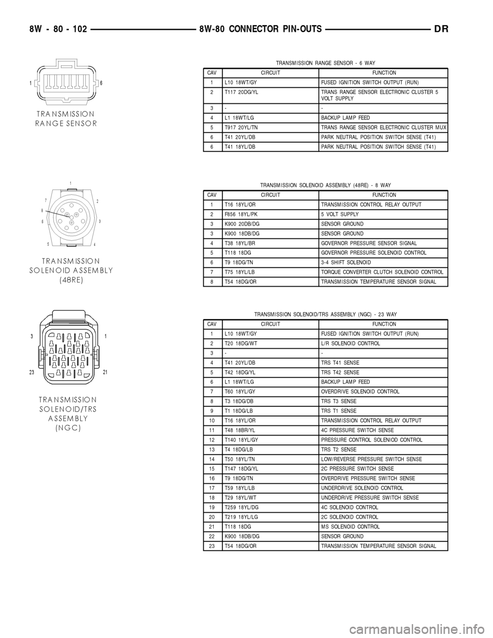
TRANSMISSION RANGE SENSOR-6WAY
CAV CIRCUIT FUNCTION
1 L10 18WT/GY FUSED IGNITION SWITCH OUTPUT (RUN)
2 T117 20DG/YL TRANS RANGE SENSOR ELECTRONIC CLUSTER 5
VOLT SUPPLY
3- -
4 L1 18WT/LG BACKUP LAMP FEED
5 T917 20YL/TN TRANS RANGE SENSOR ELECTRONIC CLUSTER MUX
6 T41 20YL/DB PARK NEUTRAL POSITION SWITCH SENSE (T41)
6 T41 18YL/DB PARK NEUTRAL POSITION SWITCH SENSE (T41)
TRANSMISSION SOLENOID ASSEMBLY (48RE)-8WAY
CAV CIRCUIT FUNCTION
1 T16 18YL/OR TRANSMISSION CONTROL RELAY OUTPUT
2 F856 18YL/PK 5 VOLT SUPPLY
3 K900 20DB/DG SENSOR GROUND
3 K900 18DB/DG SENSOR GROUND
4 T38 18YL/BR GOVERNOR PRESSURE SENSOR SIGNAL
5 T118 18DG GOVERNOR PRESSURE SOLENOID CONTROL
6 T9 18DG/TN 3-4 SHIFT SOLENOID
7 T75 18YL/LB TORQUE CONVERTER CLUTCH SOLENOID CONTROL
8 T54 18DG/OR TRANSMISSION TEMPERATURE SENSOR SIGNAL
TRANSMISSION SOLENOID/TRS ASSEMBLY (NGC) - 23 WAY
CAV CIRCUIT FUNCTION
1 L10 18WT/GY FUSED IGNITION SWITCH OUTPUT (RUN)
2 T20 18DG/WT L/R SOLENOID CONTROL
3- -
4 T41 20YL/DB TRS T41 SENSE
5 T42 18DG/YL TRS T42 SENSE
6 L1 18WT/LG BACKUP LAMP FEED
7 T60 18YL/GY OVERDRIVE SOLENOID CONTROL
8 T3 18DG/DB TRS T3 SENSE
9 T1 18DG/LB TRS T1 SENSE
10 T16 18YL/OR TRANSMISSION CONTROL RELAY OUTPUT
11 T48 18BR/YL 4C PRESSURE SWITCH SENSE
12 T140 18YL/GY PRESSURE CONTROL SOLENIOD CONTROL
13 T4 18DG/LB TRS T2 SENSE
14 T50 18YL/TN LOW/REVERSE PRESSURE SWITCH SENSE
15 T147 18DG/YL 2C PRESSURE SWITCH SENSE
16 T9 18DG/TN OVERDRIVE PRESSURE SWITCH SENSE
17 T59 18YL/LB UNDERDRIVE SOLENOID CONTROL
18 T29 18YL/WT UNDERDRIVE PRESSURE SWITCH SENSE
19 T259 18YL/DG 4C SOLENOID CONTROL
20 T219 18YL/LG 2C SOLENOID CONTROL
21 T118 18DG MS SOLENOID CONTROL
22 K900 18DB/DG SENSOR GROUND
23 T54 18DG/OR TRANSMISSION TEMPERATURE SENSOR SIGNAL
8W - 80 - 102 8W-80 CONNECTOR PIN-OUTSDR
Page 1296 of 2627

(1) Start the engine.
(2) Spray a small stream of water (spray bottle) at
the suspected leak area.
(3) If engine RPM'S change, the area of the sus-
pected leak has been found.
(4) Repair as required.
REMOVAL
(1) Disconnect negative cable from battery.
(2) Remove resonator assembly and air inlet hose.
(3) Disconnect throttle and speed control cables.
(4) Disconnect electrical connectors for the follow-
ing components: Refer to FUEL SYSTEM for compo-
nent locations.
²Manifold Absolute Pressure (MAP) Sensor
²Intake Air Temperature (IAT) Sensor
²Throttle Position (TPS) Sensor
²Coolant Temperature (CTS) Sensor
²Idle Air Control (IAC) Motor
(5) Disconnect vapor purge hose, brake booster
hose, speed control servo hose, positive crankcase
ventilation (PCV) hose.
(6) Disconnect generator electrical connections.
(7) Disconnect air conditioning compressor electri-
cal connections.
(8) Disconnect left and right radio suppressor
straps.
(9) Disconnect and remove ignition coil towers.
(10) Remove top oil dipstick tube retaining bolt
and ground strap.
(11) Bleed fuel system (Refer to 14 - FUEL SYS-
TEM/FUEL DELIVERY - STANDARD PROCE-
DURE).
(12) Remove fuel rail.
(13) Remove throttle body assembly and mounting
bracket.
(14) Drain cooling system below coolant tempera-
ture level (Refer to 7 - COOLING - STANDARD
PROCEDURE).
(15) Remove the heater hoses from the engine
front cover and the heater core.
(16) Unclip and remove heater hoses and tubes
from intake manifold.
(17) Remove coolant temperature sensor (Refer to
7 - COOLING/ENGINE/ENGINE COOLANT TEMP
SENSOR - REMOVAL).
(18) Remove intake manifold retaining fasteners in
reverse order of tightening sequence.
(19) Remove intake manifold.
INSTALLATION
(1) Install intake manifold gaskets.
(2) Install intake manifold.
(3) Install intake manifold retaining bolts and
tighten in sequence shown in to 12 N´m (105 in. lbs.)
(Fig. 89).(4) Install left and right radio suppressor straps.
(5) Install throttle body assembly.
(6) Connect throttle cable and speed control cable
to throttle body.
(7) Install fuel rail.
(8) Install ignition coil towers.
(9) Position and install heater hoses and tubes
onto intake manifold.
(10) Install the heater hoses to the heater core and
engine front cover.
(11) Connect electrical connectors for the following
components:
²Manifold Absolute Pressure (MAP) Sensor
²Intake Air Temperature (IAT) Sensor
²Throttle Position (TPS) Sensor
²Coolant Temperature (CTS) Sensor
²Idle Air Control (IAC) Motor
²Ignition coil towers
²Fuel injectors
(12) Install top oil dipstick tube retaining bolt and
ground strap.
(13) Connect generator electrical connections.
(14) Connect Vapor purge hose, Brake booster
hose, Speed control servo hose, Positive crankcase
ventilation (PCV) hose.
(15) Fill cooling system (Refer to 7 - COOLING -
STANDARD PROCEDURE).
(16) Install resonator assembly and air inlet hose.
(17) Connect negative cable to battery.
Fig. 89 Intake Manifold Tightening Sequence
DRENGINE - 3.7L 9 - 73
INTAKE MANIFOLD (Continued)
Page 1383 of 2627

(16) Unclip and remove heater hoses and tubes
from intake manifold (Fig. 108).
(17) Remove coolant temperature sensor (Refer to
7 - COOLING/ENGINE/ENGINE COOLANT TEM-
PERATURE SENSO - REMOVAL).
(18) Remove intake manifold retaining fasteners in
reverse order of tightening sequence (Fig. 109).
(19) Remove intake manifold.CLEANING
NOTE: There is NO approved repair procedure for the
intake manifold. If severe damage is found during
inspection, the intake manifold must be replaced.
Before installing the intake manifold thoroughly
clean the mating surfaces. Use a suitable cleaning
solvent, then air dry.
INSPECTION
(1) Inspect the intake sealing surface for cracks,
nicks and distortion.
(2) Inspect the intake manifold vacuum hose fit-
tings for looseness or blockage.
(3) Inspect the manifold to throttle body mating
surface for cracks, nicks and distortion.
INSTALLATION
(1) Install intake manifold gaskets.
(2) Position intake manifold.
(3) Install intake manifold retaining bolts and
tighten in sequence shown in (Fig. 109) to 12 N´m
(105 in. lbs.).
(4) Install left and right radio suppressor straps.
(5) Install throttle body assembly.
(6) Install throttle cable bracket.
(7) Connect throttle cable and speed control cable
to throttle body.
(8) Install fuel rail (Refer to 14 - FUEL SYSTEM/
FUEL DELIVERY/FUEL RAIL - INSTALLATION).
(9) Install ignition coil towers (Refer to 8 - ELEC-
TRICAL/IGNITION CONTROL/IGNITION COIL -
INSTALLATION).
(10) Position and install heater hoses and tubes
onto intake manifold.
(11) Install the heater hoses to the heater core and
engine front cover.
(12) Connect electrical connectors for the following
components:
²Manifold Absolute Pressure (MAP) Sensor
²Intake Air Temperature (IAT) Sensor
²Throttle Position (TPS) Sensor
²Coolant Temperature (CTS) Sensor
²Idle Air Control (IAC) Motor
²Ignition coil towers
²Fuel injectors
(13) Install top oil dipstick tube retaining bolt and
ground strap.
(14) Connect generator electrical connections.
(15) Connect Brake booster hose and Positive
crankcase ventilation (PCV) hose.
(16) Fill cooling system (Refer to 7 - COOLING -
STANDARD PROCEDURE).
(17) Install resonator assembly and air inlet hose.
(18) Connect negative cable to battery.
Fig. 108 Heater Hoses and Tubes Removal /
Installation
1 - HEATER HOSES AND TUBES
2 - ROUTING/RETAINING CLIPS
Fig. 109 Intake Manifold Tightening Sequence
9 - 160 ENGINE - 4.7LDR
INTAKE MANIFOLD (Continued)
Page 1597 of 2627

REMOVAL
The fuel pump relay is located in the Power Distri-
bution Center (PDC) (Fig. 13). Refer to label on PDC
cover for relay location.
(1) Remove PDC cover.
(2) Remove relay from PDC.
(3) Check condition of relay terminals and PDC
connector terminals for damage or corrosion. Repair
if necessary before installing relay.
(4) Check for pin height (pin height should be the
same for all terminals within the PDC connector).
Repair if necessary before installing relay.
INSTALLATION
The fuel pump relay is located in the Power Distri-
bution Center (PDC). Refer to label on PDC cover for
relay location.
(1) Install relay to PDC.
(2) Install cover to PDC.
IDLE AIR CONTROL MOTOR
DESCRIPTION
A separate IAC motor is not used with the 5.7L V-8
engine.
The IAC stepper motor is mounted to the throttle
body, and regulates the amount of air bypassing the
control of the throttle plate. As engine loads and
ambient temperatures change, engine rpm changes.
A pintle on the IAC stepper motor protrudes into apassage in the throttle body, controlling air flow
through the passage. The IAC is controlled by the
Powertrain Control Module (PCM) to maintain the
target engine idle speed.
OPERATION
A separate IAC motor is not used with the 5.7L V-8
engine.
At idle, engine speed can be increased by retract-
ing the IAC motor pintle and allowing more air to
pass through the port, or it can be decreased by
restricting the passage with the pintle and diminish-
ing the amount of air bypassing the throttle plate.
The IAC is called a stepper motor because it is
moved (rotated) in steps, or increments. Opening the
IAC opens an air passage around the throttle blade
which increases RPM.
The PCM uses the IAC motor to control idle speed
(along with timing) and to reach a desired MAP dur-
ing decel (keep engine from stalling).
The IAC motor has 4 wires with 4 circuits. Two of
the wires are for 12 volts and ground to supply elec-
trical current to the motor windings to operate the
stepper motor in one direction. The other 2 wires are
also for 12 volts and ground to supply electrical cur-
rent to operate the stepper motor in the opposite
direction.
To make the IAC go in the opposite direction, the
PCM just reverses polarity on both windings. If only
1 wire is open, the IAC can only be moved 1 step
(increment) in either direction. To keep the IAC
motor in position when no movement is needed, the
PCM will energize both windings at the same time.
This locks the IAC motor in place.
In the IAC motor system, the PCM will count
every step that the motor is moved. This allows the
PCM to determine the motor pintle position. If the
memory is cleared, the PCM no longer knows the
position of the pintle. So at the first key ON, the
PCM drives the IAC motor closed, regardless of
where it was before. This zeros the counter. From
this point the PCM will back out the IAC motor and
keep track of its position again.
When engine rpm is above idle speed, the IAC is
used for the following:
²Off-idle dashpot (throttle blade will close quickly
but idle speed will not stop quickly)
²Deceleration air flow control
²A/C compressor load control (also opens the pas-
sage slightly before the compressor is engaged so
that the engine rpm does not dip down when the
compressor engages)
²Power steering load control
The PCM can control polarity of the circuit to con-
trol direction of the stepper motor.
Fig. 13 PDC LOCATION
1 - BATTERY
2 - INTEGRATED POWER MODULE (IPM)
14 - 28 FUEL INJECTION - GASDR
FUEL PUMP RELAY (Continued)
Page 1710 of 2627

(15) Note position of input shaft, shift shaft, forks
and geartrain components in housing (Fig. 14).
SHIFT/FORK SHAFTS AND REVERSE IDLER
SEGMENT
(1) Place a shop towel over the shaft lever to con-
tain the lever detent ball and spring.
(2) Rotate lever and bushing upward out of the
shift forks and catch ball and spring (Fig. 15).
(3) Unseat shift socket roll pin with Remover 6858.
Position remover on shift shaft and center tool over
the roll pin. Verify tool legs are firmly seated on the
shift socket (Fig. 16).
(4) Tilt socket toward the side of the case to avoid
trapping the pin between the gear teeth.
(5) Tighten remover to press the roll pin down-
ward and out of the shift socket (Fig. 16).
NOTE: Roll pin must only clear the shift shaft. Do
not push the pin into the geartrain.
Fig. 14 GEARTRAIN AND SHIFT COMPONENT
1 - SHIFT SHAFT
2 - BUSHING
3 - REAR HOUSING
4 - REVERSE IDLER AND SUPPORT
5 - OUTPUT SHAFT AND GEARS
6 - COUNTERSHAFT
7 - 1-2 FORK
8 - INPUT SHAFT
9 - 3-4 FORK
Fig. 15 DETENT SPRING AND BALL
1 - SHAFT LEVER
2 - SPRING AND BALL
3 - MAGNET
Fig. 16 SHIFT SOCKET
1 - REMOVER
2 - SHIFT SOCKET
DRMANUAL TRANSMISSION - NV3500 21 - 7
MANUAL TRANSMISSION - NV3500 (Continued)
Page 1711 of 2627

(6) Drive out shift bushing and lever roll pin with
a hammer and punch (Fig. 17).
NOTE: Use proper size punch to avoid bending the
shift shaft.
(7) Pull shift shaft straight out of rear housing,
shift socket, fifth-reverse fork and 1-2 fork (Fig. 18).
(8) Remove shift socket from rear housing (Fig.
19).
(9) Remove shaft lever and bushing (Fig. 20).
(10) Rotate 3-4 fork around synchro sleeve until
fork clears shift arms on 1-2 and fifth-reverse forks,
then remove 3-4 fork (Fig. 21).
Fig. 17 SHIFT SHAFT LEVER & BUSHING ROLL PIN
1 - PIN PUNCH
2 - BUSHING AND LEVER
3 - SHIFT SHAFT
Fig. 18 SHIFT SHAFT
1 - SHIFT SHAFT
2 - 3-4 FORK
3 - SHAFT DETENT NOTCHES
Fig. 19 SHIFT SOCKET & ROLL PIN
1 - SHAFT BORE
2 - ROLL PIN
3 - SHIFT SOCKET
Fig. 20 SHIFT SHAFT LEVER & BUSHING
1 - SHAFT LEVER AND BUSHING
2 - 3-4 FORK
Fig. 21 3-4 SHIFT FORK
1 - 3-4 FORK
2 - 1-2 AND 5TH-REVERSE FORK ARMS
3 - 3-4 SYNCHRO SLEEVE
21 - 8 MANUAL TRANSMISSION - NV3500DR
MANUAL TRANSMISSION - NV3500 (Continued)