Removal DODGE RAM 1500 1998 2.G Workshop Manual
[x] Cancel search | Manufacturer: DODGE, Model Year: 1998, Model line: RAM 1500, Model: DODGE RAM 1500 1998 2.GPages: 2627
Page 2278 of 2627

have not been met. This is in an attempt to notify
the driver that the transmission needs to be put into
NEUTRAL, the vehicle speed is too great, or some
other condition outlined (other than a diagnostic fail-
ure that would prevent this shift) elsewhere (Refer to
8 - ELECTRICAL/ELECTRONIC CONTROL MOD-
ULES/TRANSFER CASE CONTROL MODULE -
OPERATION) is not met. Note that this flashing will
continue indefinitely until the conditions are eventu-
ally met, or the selector switch position is changed,
or if diagnostic routines no longer allow the
requested shift.
²
If the driver attempts to make a shift into transfer
case NEUTRAL, and any of the driver controllable con-
ditions are not met, the request will be ignored until all
of the conditions are met or until the NEUTRAL select
button is released. Additionally the neutral lamp will
flash, or begin to flash while the button is depressed
and operator controllable conditions are not being met.
All of the LED's except the Neutral will flash if any of
the operator controllable conditions for shifting are not
met while the Neutral button is depressed. This9toggle9
type of feature is necessary because the TCCM would
interpret another request immediately after the shift
into transfer case NEUTRAL has completed.
²No LED's illuminated indicate a fault in the
transfer case control system.
SHIFT MOTOR
DESCRIPTION
The shift motor (Fig. 96) consists of a permanent
magnet D.C. motor with gear reduction to convert a
high speed-low torque device into a low speed-high
torque device. The output of the device is coupled to
a shaft which internally moves the mode and range
forks that change the transfer case operating ranges.
The motor is rated at 25 amps maximum at 72É F
with 10 volts at the motor leads.
OPERATION
The transfer case shift motor responds to the
Transfer Case Control Module (TCCM) commands to
move the transfer case shift sector bi-directionally, as
required, to obtain the transfer case operating mode
indicated by the instrument panel mounted selector
switch.
REMOVAL
NOTE: New shift motor assemblies are shipped in
the 2WD/AWD position. If a new shift motor assem-
bly will be installed, it will be necessary to shift the
transfer case to the 2WD/AWD position prior to
motor removal.(1) Raise the vehicle on a suitable hoist.
(2) Disengage the wiring connectors from the shift
motor and mode sensor.
(3) Remove the bolts holding the shift motor and
mode sensor assembly onto the transfer case.
(4) Separate the shift motor and mode sensor
assembly from the transfer case.
INSTALLATION
(1) Verify that the shift sector o-ring is clean and
properly positioned over the shift sector and against
the transfer case.
NOTE: Verify that the shift motor position and sec-
tor shaft orientation are aligned. It may be neces-
sary to manually shift the transfer case if the shift
motor and sector shaft are not aligned.
(2) Position the shift motor and mode sensor
assembly onto the transfer case.
(3) Install the bolts to hold the assembly onto the
transfer case. Tighten the bolts to 16-24 N´m (12-18
ft.lbs.).
CAUTION: If the original shift motor and mode sen-
sor assembly bolts are reused, be sure to use
MoparTLock & Seal or LoctiteŸ 242 to replenish
the lock patch material originally found on the bolts
(4) Engage the wiring connectors to the shift motor
and mode sensor.
(5) Refill the transfer case as necessary.
(6) Lower vehicle and verify transfer case
operation.
Fig. 96 Shift Motor - Shown Inverted - Typical
1 - SHIFT MOTOR
DRTRANSFER CASE - NV273 21 - 575
SELECTOR SWITCH (Continued)
Page 2280 of 2627

TIRES/WHEELS
TABLE OF CONTENTS
page page
TIRES/WHEELS
DIAGNOSIS AND TESTING - TIRE AND
WHEEL RUNOUT......................1
STANDARD PROCEDURE
STANDARD PROCEDURE - TIRE ROTATION . 3
STANDARD PROCEDURE - MATCH
MOUNTING...........................3
STANDARD PROCEDURE - TIRE AND
WHEEL BALANCE......................4
TIRES
DESCRIPTION
DESCRIPTION - SPARE TIRE /
TEMPORARY.........................6
DESCRIPTION - TIRES..................6
DESCRIPTION - RADIAL ± PLY TIRES......6
DESCRIPTION - TIRE PRESSURE FOR
HIGH SPEEDS.........................7
DESCRIPTION - REPLACEMENT TIRES.....7
DESCRIPTION - TIRE INFLATION
PRESSURES..........................7
DIAGNOSIS AND TESTING
DIAGNOSIS AND TESTING - PRESSURE
GAUGES.............................7
DIAGNOSIS AND TESTING - TIRE NOISE
OR VIBRATION........................7
DIAGNOSIS AND TESTING - TREAD WEAR
INDICATORS..........................8
DIAGNOSIS AND TESTING - TIRE WEAR
PATTERNS...........................8
DIAGNOSIS AND TESTING - TIRE/VEHICLE
LEAD................................8STANDARD PROCEDURE - REPAIRING
LEAKS..............................10
SPECIFICATIONS
TIRE REVOLUTIONS PER MILE..........10
WHEELS
DESCRIPTION.........................11
OPERATION...........................11
DIAGNOSIS AND TESTING
WHEEL INSPECTION..................11
STANDARD PROCEDURE
STANDARD PROCEDURE - WHEEL
REPLACEMENT.......................12
STANDARD PROCEDURE - DUAL REAR
WHEEL INSTALLATION.................12
SPECIFICATIONS
TORQUE CHART......................13
STUDS
REMOVAL.............................14
INSTALLATION.........................14
WHEEL COVER
REMOVAL.............................14
INSTALLATION
INSTALLATION - REAR.................14
INSTALLATION - FRONT................14
SPARE TIRE
DESCRIPTION
DESCRIPTION - SPARE / TEMPORARY
TIRE...............................15
DESCRIPTION - FULL SIZE, SPARE WHEEL
WITH MATCHING TIRE.................15
TIRES/WHEELS
DIAGNOSIS AND TESTING - TIRE AND WHEEL
RUNOUT
Radial runout is the difference between the high
and low points on the tire or wheel (Fig. 1).
Lateral runout is thewobbleof the tire or wheel.
Radial runout of more than 1.5 mm (.060 inch)
measured at the center line of the tread may cause
the vehicle to shake.Lateral runout of more than 2.0 mm (.080 inch)
measured near the shoulder of the tire may cause the
vehicle to shake.
Sometimes radial runout can be reduced. Relocate
the wheel and tire assembly on the mounting studs
(See Method 1). If this does not reduce runout to an
acceptable level, the tire can be rotated on the wheel.
(See Method 2).
DRTIRES/WHEELS 22 - 1
Page 2293 of 2627

STUDS
REMOVAL
(1) Raise and support the vehicle.
(2) Remove the wheel and tire assembly.
(3) Remove the brake caliper, caliper adapter and
rotor, (Refer to 5 - BRAKES/HYDRAULIC/MECHAN-
ICAL/ROTORS - REMOVAL).
(4) Remove the stud from the hub with Remover
C-4150A (Fig. 25).
INSTALLATION
(1) Install the new stud into the hub flange.
(2) Install the three washers onto the stud, then
install the lug nut with the flat side of the nut
against the washers.
(3) Tighten the lug nut until the stud is pulled
into the hub flange. Verify that the stud is properly
seated into the flange.
(4) Remove the lug nut and washers.
(5) Install the brake rotor, caliper adapter, and cal-
iper, (Refer to 5 - BRAKES/HYDRAULIC/MECHAN-
ICAL/ROTORS - INSTALLATION).
(6) Install the wheel and tire assembly, (Refer to
22 - TIRES/WHEELS/WHEELS - STANDARD PRO-
CEDURE), use new the lug nut on stud or studs that
were replaced.
(7) Remove the support and lower vehicle.
WHEEL COVER
REMOVAL
NOTE: The hub caps must be removed before rais-
ing the vehicle off the ground.NOTE: You must use the flat end of the hub/cap
remover/installer combination tool to pry off the
wheel skins. Insert the flat tip completely and using
a back and forth motion, loosen the wheel skin.
repeat this procedure around the tire until the wheel
skin pops off.
(1) On 2500/3500 single rear wheel (SRW) models,
insert a hub/cap remover/installer combination tool
using the blade on the end of the tool to pry the cap
off in a back and forth motion.
(2) On 3500 models with dual rear wheels (DRW),
you must first remove the hub caps. The hub/cap
remover/installer combination tool must be inserted
in the pry off notch of the rear hub caps.
(3) Position the hub/cap remover/installer combina-
tion tool and pull out on the tool firmly. The cap
should come off.
(4) The wheel skins can now be removed from the
wheel.
(5) On 3500 models front hub caps use the hub/cap
remover/installer combination tool to pry off the cap
in a back and forth motion. The wheel skins can now
be removed.
INSTALLATION
INSTALLATION - REAR
(1) Install one 1 1/2 in. valve stem extension on
each rear inner wheel.
NOTE: A 3/8 in. drive 10mm deep wheel socket with
a 10 in. or greater extension can be used to remove
the existing valve stem cap and install the exten-
sion.
(2) Install one 1 in. valve stem extension on each
outer wheel.
(3) Align the cooling windows of the wheel skin
with the cooling windows of the wheel. Seat one side
of the wheel skin's retainer onto the wheel. Using a
rubber mallet, strike thew wheel skin on the outer
circumference. Strike at several locations around the
circumference until the skin is fully seated.
NOTE: The wheel skin and the hub cap are fully
seated when there is a consistent gap between the
skin/cap and the wheel.
(4) Tug on the hub/cap wheel skin to ensure that
they are properly installed.
INSTALLATION - FRONT
(1) Align the valve stem with the notch in the
wheel skin.
Fig. 25 Wheel Stud Removal
1 - REMOVER
2 - WHEEL STUD
22 - 14 TIRES/WHEELSDR
Page 2302 of 2627

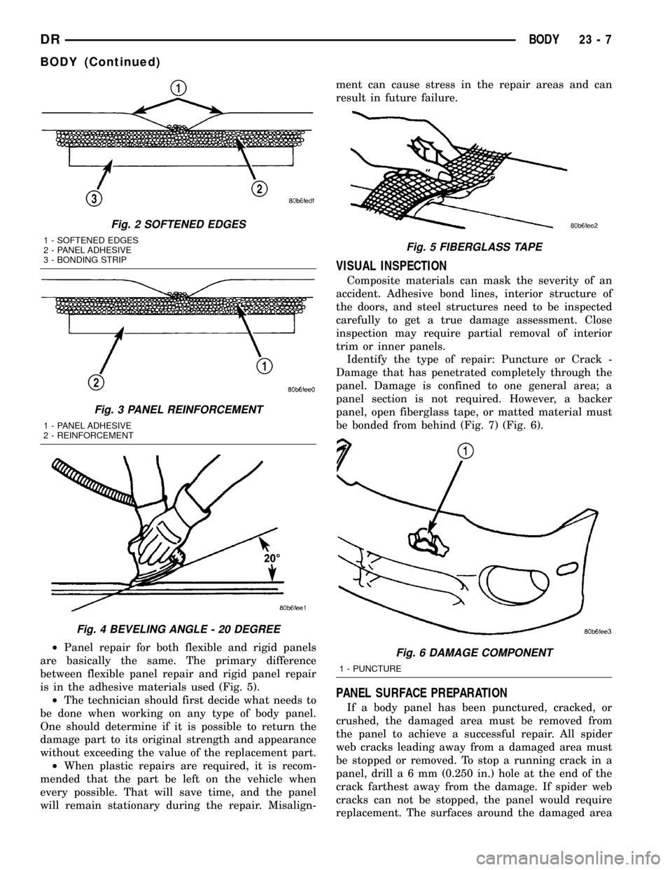
²Panel repair for both flexible and rigid panels
are basically the same. The primary difference
between flexible panel repair and rigid panel repair
is in the adhesive materials used (Fig. 5).
²The technician should first decide what needs to
be done when working on any type of body panel.
One should determine if it is possible to return the
damage part to its original strength and appearance
without exceeding the value of the replacement part.
²When plastic repairs are required, it is recom-
mended that the part be left on the vehicle when
every possible. That will save time, and the panel
will remain stationary during the repair. Misalign-ment can cause stress in the repair areas and can
result in future failure.
VISUAL INSPECTION
Composite materials can mask the severity of an
accident. Adhesive bond lines, interior structure of
the doors, and steel structures need to be inspected
carefully to get a true damage assessment. Close
inspection may require partial removal of interior
trim or inner panels.
Identify the type of repair: Puncture or Crack -
Damage that has penetrated completely through the
panel. Damage is confined to one general area; a
panel section is not required. However, a backer
panel, open fiberglass tape, or matted material must
be bonded from behind (Fig. 7) (Fig. 6).
PANEL SURFACE PREPARATION
If a body panel has been punctured, cracked, or
crushed, the damaged area must be removed from
the panel to achieve a successful repair. All spider
web cracks leading away from a damaged area must
be stopped or removed. To stop a running crack in a
panel, drilla6mm(0.250 in.) hole at the end of the
crack farthest away from the damage. If spider web
cracks can not be stopped, the panel would require
replacement. The surfaces around the damaged area
Fig. 2 SOFTENED EDGES
1 - SOFTENED EDGES
2 - PANEL ADHESIVE
3 - BONDING STRIP
Fig. 3 PANEL REINFORCEMENT
1 - PANEL ADHESIVE
2 - REINFORCEMENT
Fig. 4 BEVELING ANGLE - 20 DEGREE
Fig. 5 FIBERGLASS TAPE
Fig. 6 DAMAGE COMPONENT
1 - PUNCTURE
DRBODY 23 - 7
BODY (Continued)
Page 2310 of 2627

TAILGATE
TABLE OF CONTENTS
page page
CHECK CABLE
REMOVAL.............................15
INSTALLATION.........................15
COVER
REMOVAL.............................16
INSTALLATION.........................16
HINGE
REMOVAL.............................16
INSTALLATION.........................16
LATCH
REMOVAL.............................16INSTALLATION.........................16
LATCH STRIKER
REMOVAL.............................16
INSTALLATION.........................17
RELEASE HANDLE/LATCH REMOTE
REMOVAL.............................17
INSTALLATION.........................17
TAILGATE
REMOVAL.............................17
INSTALLATION.........................17
CHECK CABLE
REMOVAL
(1) Open tailgate.
(2) Pry lock tab outward to clear stud head on
cargo box (Fig. 1).
(3) Push cable end forward until stud head is in
clearance hole portion of cable end.
(4) Separate cable end from stud.
(5) Remove screw attaching cable to tailgate. (Fig.
2)
(6) Separate check cable from tailgate.
INSTALLATION
(1) Position check cable on tailgate.
(2) Install bolt attaching small end of cable to tail-
gate.
(3) Tighten tailgate check cable bolt to 23 N´m (17
ft. lbs.).
(4) Position large end of cable onto stud head and
slide downward to secure lock tab.
Fig. 1 Tailgate Check
1 - TAILGATE STRIKER
2 - SCREW DRIVER
3 - TAILGATE CHECK CABLE
4 - LOCK TAB
Fig. 2 LATCH HANDLE - LATCH
1 - EXTERIOR HANDLE
2 - CONTROL ASSEMBLY
3 - NUTS (2)
4 - TAILGATE
5-LATCH
6 - CHECK CABLE
7 - CHECK/LATCH BOLT
8 - LATCH BOLT
DRTAILGATE 23 - 15
Page 2311 of 2627

COVER
REMOVAL
(1) Open the tailgate.
(2) Remove the eight screws and remove tailgate
liner, if equipped.
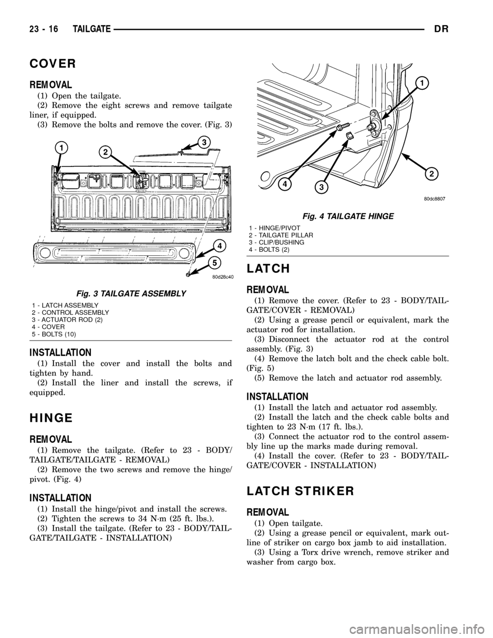
(3) Remove the bolts and remove the cover. (Fig. 3)
INSTALLATION
(1) Install the cover and install the bolts and
tighten by hand.
(2) Install the liner and install the screws, if
equipped.
HINGE
REMOVAL
(1) Remove the tailgate. (Refer to 23 - BODY/
TAILGATE/TAILGATE - REMOVAL)
(2) Remove the two screws and remove the hinge/
pivot. (Fig. 4)
INSTALLATION
(1) Install the hinge/pivot and install the screws.
(2) Tighten the screws to 34 N´m (25 ft. lbs.).
(3) Install the tailgate. (Refer to 23 - BODY/TAIL-
GATE/TAILGATE - INSTALLATION)
LATCH
REMOVAL
(1) Remove the cover. (Refer to 23 - BODY/TAIL-
GATE/COVER - REMOVAL)
(2) Using a grease pencil or equivalent, mark the
actuator rod for installation.
(3) Disconnect the actuator rod at the control
assembly. (Fig. 3)
(4) Remove the latch bolt and the check cable bolt.
(Fig. 5)
(5) Remove the latch and actuator rod assembly.
INSTALLATION
(1) Install the latch and actuator rod assembly.
(2) Install the latch and the check cable bolts and
tighten to 23 N´m (17 ft. lbs.).
(3) Connect the actuator rod to the control assem-
bly line up the marks made during removal.
(4) Install the cover. (Refer to 23 - BODY/TAIL-
GATE/COVER - INSTALLATION)
LATCH STRIKER
REMOVAL
(1) Open tailgate.
(2) Using a grease pencil or equivalent, mark out-
line of striker on cargo box jamb to aid installation.
(3) Using a Torx drive wrench, remove striker and
washer from cargo box.
Fig. 3 TAILGATE ASSEMBLY
1 - LATCH ASSEMBLY
2 - CONTROL ASSEMBLY
3 - ACTUATOR ROD (2)
4 - COVER
5 - BOLTS (10)
Fig. 4 TAILGATE HINGE
1 - HINGE/PIVOT
2 - TAILGATE PILLAR
3 - CLIP/BUSHING
4 - BOLTS (2)
23 - 16 TAILGATEDR
Page 2312 of 2627

INSTALLATION
(1) Position striker and washer on jamb using
alignment outline as reference and install with Torx
drive wrench.
(2) Tighten the striker to 34 N´m (25 ft. lbs.).
RELEASE HANDLE/LATCH
REMOTE
REMOVAL
(1) Remove the tailgate cover. (Refer to 23 - BODY/
TAILGATE/COVER - REMOVAL)
(2) Using a grease pencil or equivalent, mark the
latch actuator rods for ease of installation.
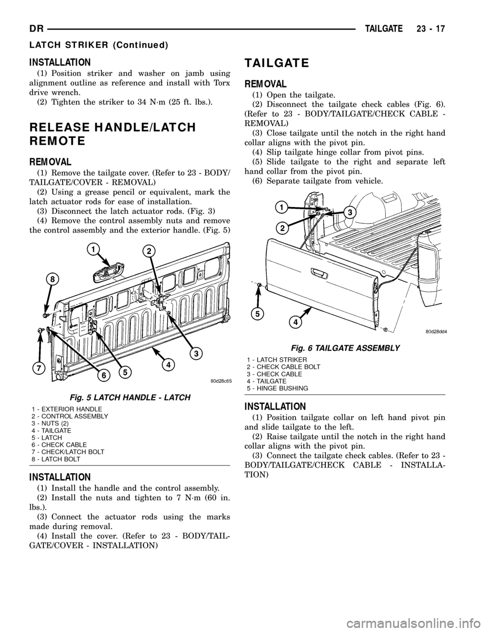
(3) Disconnect the latch actuator rods. (Fig. 3)
(4) Remove the control assembly nuts and remove
the control assembly and the exterior handle. (Fig. 5)
INSTALLATION
(1) Install the handle and the control assembly.
(2) Install the nuts and tighten to 7 N´m (60 in.
lbs.).
(3) Connect the actuator rods using the marks
made during removal.
(4) Install the cover. (Refer to 23 - BODY/TAIL-
GATE/COVER - INSTALLATION)
TAILGATE
REMOVAL
(1) Open the tailgate.
(2) Disconnect the tailgate check cables (Fig. 6).
(Refer to 23 - BODY/TAILGATE/CHECK CABLE -
REMOVAL)
(3) Close tailgate until the notch in the right hand
collar aligns with the pivot pin.
(4) Slip tailgate hinge collar from pivot pins.
(5) Slide tailgate to the right and separate left
hand collar from the pivot pin.
(6) Separate tailgate from vehicle.
INSTALLATION
(1) Position tailgate collar on left hand pivot pin
and slide tailgate to the left.
(2) Raise tailgate until the notch in the right hand
collar aligns with the pivot pin.
(3) Connect the tailgate check cables. (Refer to 23 -
BODY/TAILGATE/CHECK CABLE - INSTALLA-
TION)
Fig. 5 LATCH HANDLE - LATCH
1 - EXTERIOR HANDLE
2 - CONTROL ASSEMBLY
3 - NUTS (2)
4 - TAILGATE
5-LATCH
6 - CHECK CABLE
7 - CHECK/LATCH BOLT
8 - LATCH BOLT
Fig. 6 TAILGATE ASSEMBLY
1 - LATCH STRIKER
2 - CHECK CABLE BOLT
3 - CHECK CABLE
4 - TAILGATE
5 - HINGE BUSHING
DRTAILGATE 23 - 17
LATCH STRIKER (Continued)
Page 2313 of 2627

DOOR - FRONT
TABLE OF CONTENTS
page page
DOOR
REMOVAL.............................18
INSTALLATION.........................18
ADJUSTMENTS
ADJUSTMENT........................19
DOOR GLASS
REMOVAL.............................20
INSTALLATION.........................20
EXTERIOR HANDLE
REMOVAL.............................20
INSTALLATION.........................21
GLASS RUN CHANNEL
REMOVAL.............................21
INSTALLATION.........................22
HINGE
REMOVAL.............................22
INSTALLATION.........................22
INSIDE HANDLE ACTUATOR
REMOVAL.............................22
INSTALLATION.........................22
LATCH
REMOVAL.............................23
INSTALLATION.........................23
ADJUSTMENTS
ADJUSTMENT........................23LATCH STRIKER
REMOVAL.............................23
INSTALLATION.........................23
ADJUSTMENTS
ADJUSTMENT........................24
LOCK CYLINDER
REMOVAL.............................24
INSTALLATION.........................24
TRIM PANEL
REMOVAL.............................24
INSTALLATION.........................24
WATERDAM
REMOVAL.............................25
INSTALLATION.........................25
WINDOW REGULATOR - POWER
REMOVAL.............................25
INSTALLATION.........................26
WINDOW REGULATOR - MANUAL
REMOVAL.............................26
INSTALLATION.........................27
SIDE VIEW MIRROR FLAG
REMOVAL.............................27
INSTALLATION.........................27
DOOR
REMOVAL
(1) Disconnect the door wire harness electrical con-
nector at the A-pillar. (Fig. 1)
(2) Using a grease pencil or equivalent, mark the
outline of the door hinges on the door to aid in instal-
lation.
(3) Support the door with a suitable lifting device.
NOTE: The epoxy bonded washers should not be
seperated from the hinge. If the washers are
removed the door may have to be re-adjusted.
(4) Remove the nuts and bolts attaching the door
hinges to the door.
INSTALLATION
(1) Support the door with a suitable lifting device
and install the door onto the hinges.
(2) Install the washers, if there were removed pre-
viously, nuts and tighten to 28 N´m (21 ft. lbs.).
(3) Connect the electrical connectors.
(4) Adjust the door as necessary. (Refer to 23 -
BODY/DOOR - FRONT/DOOR - ADJUSTMENTS)
23 - 18 DOOR - FRONTDR
Page 2314 of 2627

ADJUSTMENTS
ADJUSTMENT
NOTE: For vehicles with four doors, it is recom-
mended that you adjust the rear door before adjust-
ing the front door. (Refer to 23 - BODY/DOORS -
REAR/DOOR - ADJUSTMENTS)
²Door adjustment measurements should be
taken from stationary or welded body panels like
the roof, rocker or quarter panels.
²During adjustment procedures, it is recom-
mended that all the hinge fasteners be loosened
except for the upper most fasteners. Adjustments
can be made using the upper bolts to hold the door
with final torque of the fasteners occurring after
correct door positioning is achieved.
²A suitable body sealant should be used when
removing or moving the hinges.
FORE/AFT
NOTE: Fore/aft (lateral) door adjustment is done by
loosening the hinge to the hinge pillar fasteners
one hinge at a time and moving the door to the cor-
rect position.
(1) Support the door with a suitable lifting device.
(2)
Loosen the hinge to hinge pillar fasteners. (Refer
to 23 - BODY/DOOR - FRONT/HINGE - REMOVAL)
(3) Adjust the door to the correct position. (Refer
to 23 - BODY/BODY STRUCTURE/GAP AND
FLUSH - SPECIFICATIONS)(4) Tighten the hinge pillar fasteners to 28 N´m
(21 ft. lbs.).
UP/DOWN
NOTE: Up/down door adjustment is done by loosen-
ing either the hinge to the hinge pillar fasteners or
the hinge to door fasteners and moving the door to
the correct position.
NOTE: When adjustment of the door requires the
loosening of the door to hinge fasteners, it will be
necessary to separate the epoxy bonded washers
with a chisel or other suitable tool.
NOTE: When the up/down adjustments are done
correctly, the top of the door is positioned over
flush to the roof. (Refer to 23 - BODY/BODY STRUC-
TURE/GAP AND FLUSH - SPECIFICATIONS)
(1) Support the door with a suitable lifting device.
(2) Loosen the latch striker bolts. (Refer to 23 -
BODY/DOOR - FRONT/LATCH STRIKER -
REMOVAL)
(3) Loosen the hinge to door fasteners (Refer to 23
- BODY/DOOR - FRONT/DOOR - REMOVAL) or
loosen the hinge to hinge pillar fasteners (Refer to 23
- BODY/DOOR - FRONT/HINGE - REMOVAL).
(4) Adjust the door to the correct position. (Refer
to 23 - BODY/BODY STRUCTURE/GAP AND
FLUSH - SPECIFICATIONS)
(5) Tighten the hinge pillar fasteners or the door
to hinges fasteners to 28 N´m (21 ft. lbs.).
(6) Tighten the latch striker bolts. (Refer to 23 -
BODY/DOOR - FRONT/LATCH STRIKER - INSTAL-
LATION)
IN/OUT
NOTE: In/out door adjustment is done by loosening
the hinge to door fasteners one hinge at a time and
moving the door to the correct position.
NOTE: When adjustment of the door requires the
loosening of the door to hinge fasteners, it will be
necessary to separate the epoxy bonded washers
with a chisel or other suitable tool.
(1) Support the door with a suitable lifting device.
(2) Loosen the latch striker bolts. (Refer to 23 -
BODY/DOOR - FRONT/LATCH STRIKER -
REMOVAL)
(3) Loosen the hinge to door fasteners. (Refer to 23
- BODY/DOOR - FRONT/DOOR - REMOVAL)
Fig. 1 FRONT DOOR
1 - NUTS (2)
2 - UPPER HINGE
3 - STUDS
4 - FRONT DOOR
5 - WIRE HARNESS
6 - LOWER HINGE
7 - ELECTRICAL CONNECTORS (2)
8 - BOLTS (2)
DRDOOR - FRONT 23 - 19
DOOR (Continued)
Page 2315 of 2627

(4) Adjust the door to the correct position. (Refer
to 23 - BODY/BODY STRUCTURE/GAP AND
FLUSH - SPECIFICATIONS)
(5) Tighten the door to hinges fasteners to 28 N´m
(21 ft. lbs.).
(6) Tighten the latch striker bolts. (Refer to 23 -
BODY/DOOR - FRONT/LATCH STRIKER - INSTAL-
LATION)
DOOR GLASS
REMOVAL
(1) Remove the waterdam. (Refer to 23 - BODY/
DOOR - FRONT/WATERDAM - REMOVAL)
(2) Reinstall the window handle, if equipped.
(3) Remove the window switch from the door trim
panel and reconnect it to the door wire harness, if
equipped.
(4) Raise the window to the position shown and
remove the two nuts attaching the glass to the win-
dow regulator. (Fig. 2)
(5) Remove the two front run channel screws.
(Refer to 23 - BODY/DOOR - FRONT/GLASS RUN
CHANNEL - REMOVAL)
(6) Remove the inner belt molding. (Refer to 23 -
BODY/WEATHERSTRIP/SEALS/FRONT DOOR
INNER BELT WEATHERSTRIP - REMOVAL)
(7) Disengage the glass from the regulator and
lower into the door.
(8) Twist the glass forward in the door window
opening and remove.
INSTALLATION
(1) Position the glass into the window opening.(2) Engage the glass into the glass run weather-
strip.
(3) Raise the glass within the door opening and
connect the window regulator to the lift plate.
(4) Install the nuts and tighten to 10 N´m (89 in.
lbs.).
(5) Install the inner belt molding. (Refer to 23 -
BODY/WEATHERSTRIP/SEALS/FRONT DOOR
INNER BELT WEATHERSTRIP - INSTALLATION)
(6) Position the front run channel and install the
screws. (Refer to 23 - BODY/DOOR - FRONT/GLASS
RUN CHANNEL - INSTALLATION)
(7) Remove the window switch from the wire har-
ness, if equipped.
(8) Remove the window handle, if equipped.
(9) Install the waterdam. (Refer to 23 - BODY/
DOOR - FRONT/WATERDAM - INSTALLATION)
EXTERIOR HANDLE
REMOVAL
(1) Remove the door glass. (Refer to 23 - BODY/
DOOR - FRONT/DOOR GLASS - REMOVAL)
(2) Disconnect the lock switch electrical connector,
if equipped. (Fig. 3)
(3) Disconnect the actuator rods at the handle.
(4) Remove the nuts and remove the handle.
Fig. 2 DOOR GLASS POSITIONING
1 - SIGHT WINDOW
2 - WIDOW REGULATOR
3 - SIGHT WINDOW
4 - REGULATOR STABILIZER
Fig. 3 EXTERIOR HANDLE
1 - EXTERIOR HANDLE
2 - NUTS (2)
3 - ELECTRICAL CONNECTOR
4 - FRONT DOOR
5 - DOOR LATCH ASSEMBLY
6 - LATCH ACTUATOR ROD
7 - LOCK SWITCH WIRE HARNESS
8 - KEY CYLINDER ACTUATOR ROD
23 - 20 DOOR - FRONTDR
DOOR (Continued)