DODGE RAM 2001 Service Repair Manual
Manufacturer: DODGE, Model Year: 2001, Model line: RAM, Model: DODGE RAM 2001Pages: 2889, PDF Size: 68.07 MB
Page 1161 of 2889
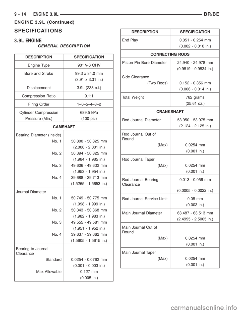
SPECIFICATIONS
3.9L ENGINE
GENERAL DESCRIPTION
DESCRIPTION SPECIFICATION
Engine Type 90É V-6 OHV
Bore and Stroke 99.3 x 84.0 mm
(3.91 x 3.31 in.)
Displacement 3.9L (238 c.i.)
Compression Ratio 9.1:1
Firing Order 1±6±5±4±3±2
Cylinder Compression 689.5 kPa
Pressure (Min.) (100 psi)
CAMSHAFT
Bearing Diameter (Inside)
No. 1 50.800 - 50.825 mm
(2.000 - 2.001 in.)
No. 2 50.394 - 50.825 mm
(1.984 - 1.985 in.)
No. 3 49.606 - 49.632 mm
(1.953 - 1.954 in.)
No. 4 39.688 - 39.713 mm
(1.5265 - 1.5653 in.)
Journal Diameter
No. 1 50.749 - 50.775 mm
(1.998 - 1.999 in.)
No. 2 50.343 - 50.368 mm
(1.982 - 1.983 in.)
No. 3 49.555 - 49.581 mm
(1.951 - 1.952 in.)
No. 4 39.637 - 39.662 mm
(1.5605 - 1.5615 in.)
Bearing to Journal
Clearance
Standard 0.0254 - 0.0762 mm
(0.001 - 0.003 in.)
Max Allowable 0.127 mm
(0.005 in.)
DESCRIPTION SPECIFICATION
End Play 0.051 - 0.254 mm
(0.002 - 0.010 in.)
CONNECTING RODS
Piston Pin Bore Diameter 24.940 - 24.978 mm
(0.9819 - 0.9834 in.)
Side Clearance
(Two Rods) 0.152 - 0.356 mm
(0.006 - 0.014 in.)
Total Weight 762 grams
(25.61 oz.)
CRANKSHAFT
Rod Journal Diameter 53.950 - 53.975 mm
(2.124 - 2.125 in.)
Rod Journal Out of
Round
(Max) 0.0254 mm
(0.001 in.)
Rod Journal Taper
(Max) 0.0254 mm
(0.001 in.)
Rod Journal Bearing
Clearance0.013 - 0.056 mm
(0.0005 - 0.0022 in.)
Rod Journal Service Limit 0.08 mm
(0.003 in.)
Main Journal Diameter 63.487 - 63.513 mm
(2.4995 - 2.5005 in.)
Main Journal Out of
Round
(Max) 0.0254 mm
(0.001 in.)
Main Journal Taper
(Max) 0.0254 mm
(0.001 in.)
9 - 14 ENGINE 3.9LBR/BE
ENGINE 3.9L (Continued)
Page 1162 of 2889
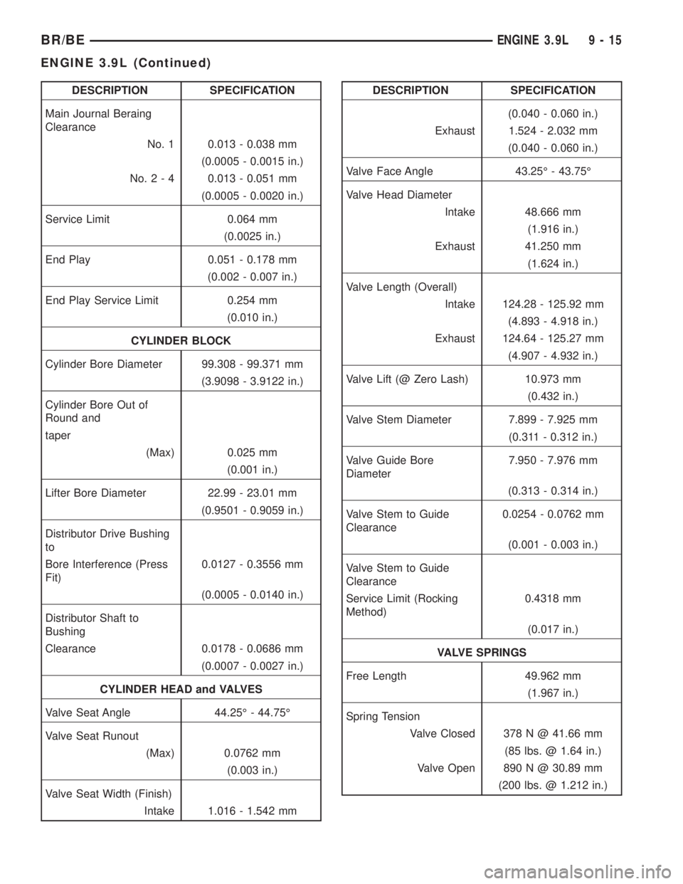
DESCRIPTION SPECIFICATION
Main Journal Beraing
Clearance
No. 1 0.013 - 0.038 mm
(0.0005 - 0.0015 in.)
No.2-40.013 - 0.051 mm
(0.0005 - 0.0020 in.)
Service Limit 0.064 mm
(0.0025 in.)
End Play 0.051 - 0.178 mm
(0.002 - 0.007 in.)
End Play Service Limit 0.254 mm
(0.010 in.)
CYLINDER BLOCK
Cylinder Bore Diameter 99.308 - 99.371 mm
(3.9098 - 3.9122 in.)
Cylinder Bore Out of
Round and
taper
(Max) 0.025 mm
(0.001 in.)
Lifter Bore Diameter 22.99 - 23.01 mm
(0.9501 - 0.9059 in.)
Distributor Drive Bushing
to
Bore Interference (Press
Fit)0.0127 - 0.3556 mm
(0.0005 - 0.0140 in.)
Distributor Shaft to
Bushing
Clearance 0.0178 - 0.0686 mm
(0.0007 - 0.0027 in.)
CYLINDER HEAD and VALVES
Valve Seat Angle 44.25É - 44.75É
Valve Seat Runout
(Max) 0.0762 mm
(0.003 in.)
Valve Seat Width (Finish)
Intake 1.016 - 1.542 mmDESCRIPTION SPECIFICATION
(0.040 - 0.060 in.)
Exhaust 1.524 - 2.032 mm
(0.040 - 0.060 in.)
Valve Face Angle 43.25É - 43.75É
Valve Head Diameter
Intake 48.666 mm
(1.916 in.)
Exhaust 41.250 mm
(1.624 in.)
Valve Length (Overall)
Intake 124.28 - 125.92 mm
(4.893 - 4.918 in.)
Exhaust 124.64 - 125.27 mm
(4.907 - 4.932 in.)
Valve Lift (@ Zero Lash) 10.973 mm
(0.432 in.)
Valve Stem Diameter 7.899 - 7.925 mm
(0.311 - 0.312 in.)
Valve Guide Bore
Diameter7.950 - 7.976 mm
(0.313 - 0.314 in.)
Valve Stem to Guide
Clearance0.0254 - 0.0762 mm
(0.001 - 0.003 in.)
Valve Stem to Guide
Clearance
Service Limit (Rocking
Method)0.4318 mm
(0.017 in.)
VALVE SPRINGS
Free Length 49.962 mm
(1.967 in.)
Spring Tension
Valve Closed 378 N @ 41.66 mm
(85 lbs. @ 1.64 in.)
Valve Open 890 N @ 30.89 mm
(200 lbs. @ 1.212 in.)
BR/BEENGINE 3.9L 9 - 15
ENGINE 3.9L (Continued)
Page 1163 of 2889
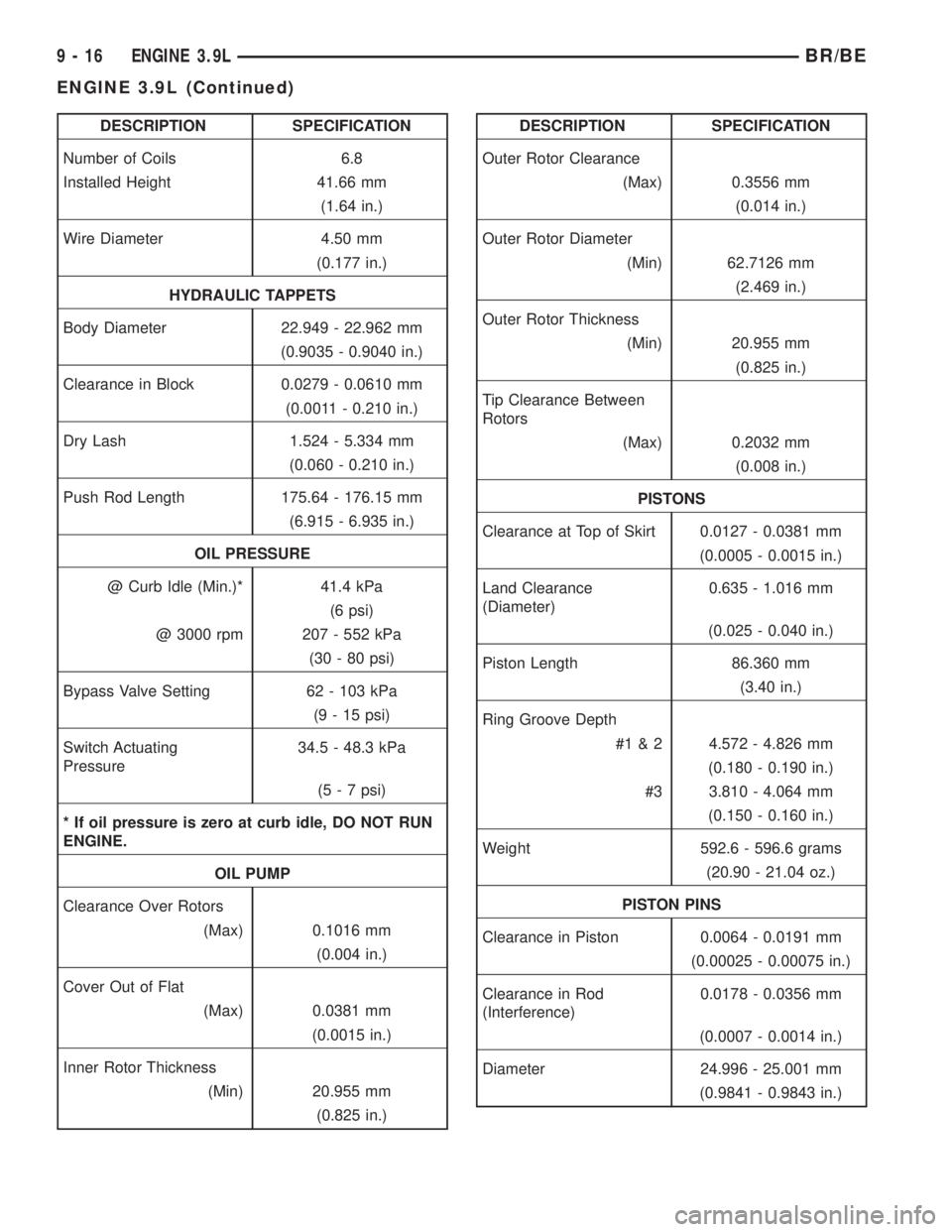
DESCRIPTION SPECIFICATION
Number of Coils 6.8
Installed Height 41.66 mm
(1.64 in.)
Wire Diameter 4.50 mm
(0.177 in.)
HYDRAULIC TAPPETS
Body Diameter 22.949 - 22.962 mm
(0.9035 - 0.9040 in.)
Clearance in Block 0.0279 - 0.0610 mm
(0.0011 - 0.210 in.)
Dry Lash 1.524 - 5.334 mm
(0.060 - 0.210 in.)
Push Rod Length 175.64 - 176.15 mm
(6.915 - 6.935 in.)
OIL PRESSURE
@ Curb Idle (Min.)* 41.4 kPa
(6 psi)
@ 3000 rpm 207 - 552 kPa
(30 - 80 psi)
Bypass Valve Setting 62 - 103 kPa
(9 - 15 psi)
Switch Actuating
Pressure34.5 - 48.3 kPa
(5 - 7 psi)
* If oil pressure is zero at curb idle, DO NOT RUN
ENGINE.
OIL PUMP
Clearance Over Rotors
(Max) 0.1016 mm
(0.004 in.)
Cover Out of Flat
(Max) 0.0381 mm
(0.0015 in.)
Inner Rotor Thickness
(Min) 20.955 mm
(0.825 in.)DESCRIPTION SPECIFICATION
Outer Rotor Clearance
(Max) 0.3556 mm
(0.014 in.)
Outer Rotor Diameter
(Min) 62.7126 mm
(2.469 in.)
Outer Rotor Thickness
(Min) 20.955 mm
(0.825 in.)
Tip Clearance Between
Rotors
(Max) 0.2032 mm
(0.008 in.)
PISTONS
Clearance at Top of Skirt 0.0127 - 0.0381 mm
(0.0005 - 0.0015 in.)
Land Clearance
(Diameter)0.635 - 1.016 mm
(0.025 - 0.040 in.)
Piston Length 86.360 mm
(3.40 in.)
Ring Groove Depth
#1 & 2 4.572 - 4.826 mm
(0.180 - 0.190 in.)
#3 3.810 - 4.064 mm
(0.150 - 0.160 in.)
Weight 592.6 - 596.6 grams
(20.90 - 21.04 oz.)
PISTON PINS
Clearance in Piston 0.0064 - 0.0191 mm
(0.00025 - 0.00075 in.)
Clearance in Rod
(Interference)0.0178 - 0.0356 mm
(0.0007 - 0.0014 in.)
Diameter 24.996 - 25.001 mm
(0.9841 - 0.9843 in.)
9 - 16 ENGINE 3.9LBR/BE
ENGINE 3.9L (Continued)
Page 1164 of 2889
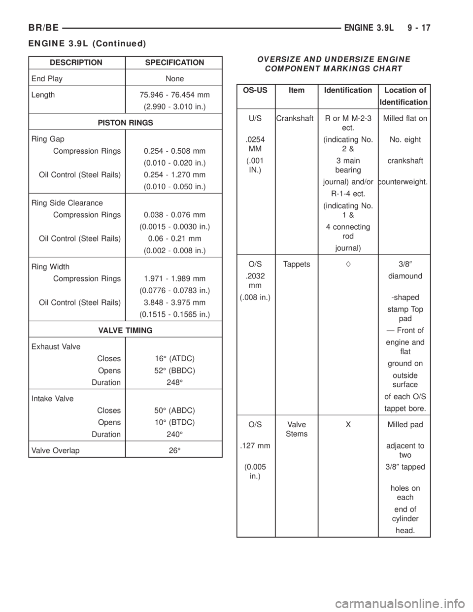
DESCRIPTION SPECIFICATION
End Play None
Length 75.946 - 76.454 mm
(2.990 - 3.010 in.)
PISTON RINGS
Ring Gap
Compression Rings 0.254 - 0.508 mm
(0.010 - 0.020 in.)
Oil Control (Steel Rails) 0.254 - 1.270 mm
(0.010 - 0.050 in.)
Ring Side Clearance
Compression Rings 0.038 - 0.076 mm
(0.0015 - 0.0030 in.)
Oil Control (Steel Rails) 0.06 - 0.21 mm
(0.002 - 0.008 in.)
Ring Width
Compression Rings 1.971 - 1.989 mm
(0.0776 - 0.0783 in.)
Oil Control (Steel Rails) 3.848 - 3.975 mm
(0.1515 - 0.1565 in.)
VALVE TIMING
Exhaust Valve
Closes 16É (ATDC)
Opens 52É (BBDC)
Duration 248É
Intake Valve
Closes 50É (ABDC)
Opens 10É (BTDC)
Duration 240É
Valve Overlap 26ÉOVERSIZE AND UNDERSIZE ENGINE
COMPONENT MARKINGS CHART
OS-US Item Identification Location of
Identification
U/S Crankshaft R or M M-2-3
ect.Milled flat on
.0254
MM(indicating No.
2&No. eight
(.001
IN.)3 main
bearingcrankshaft
journal) and/or counterweight.
R-1-4 ect.
(indicating No.
1&
4 connecting
rod
journal)
O/S TappetsL3/89
.2032
mmdiamound
(.008 in.) -shaped
stamp Top
pad
Ð Front of
engine and
flat
ground on
outside
surface
of each O/S
tappet bore.
O/S Valve
StemsX Milled pad
.127 mm adjacent to
two
(0.005
in.)3/89tapped
holes on
each
end of
cylinder
head.
BR/BEENGINE 3.9L 9 - 17
ENGINE 3.9L (Continued)
Page 1165 of 2889
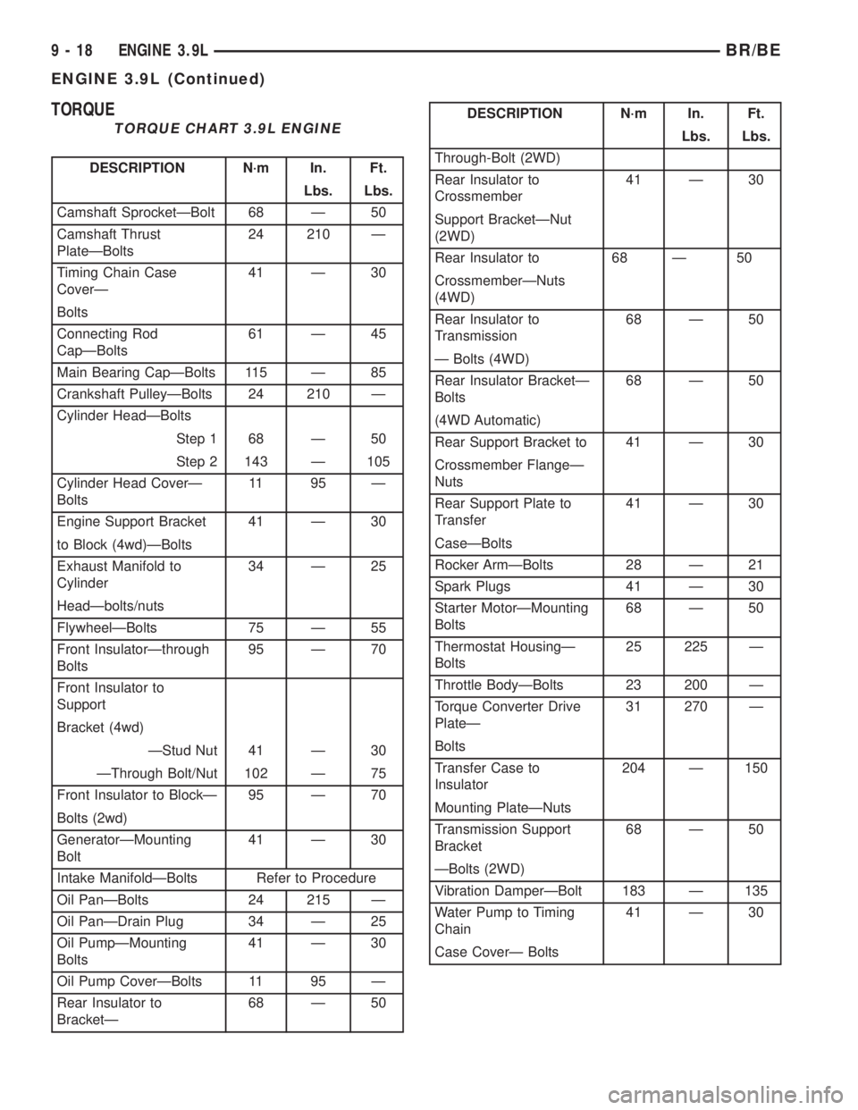
TORQUE
TORQUE CHART 3.9L ENGINE
DESCRIPTION N´m In. Ft.
Lbs. Lbs.
Camshaft SprocketÐBolt 68 Ð 50
Camshaft Thrust
PlateÐBolts24 210 Ð
Timing Chain Case
CoverÐ41 Ð 30
Bolts
Connecting Rod
CapÐBolts61 Ð 45
Main Bearing CapÐBolts 115 Ð 85
Crankshaft PulleyÐBolts 24 210 Ð
Cylinder HeadÐBolts
Step 1 68 Ð 50
Step 2 143 Ð 105
Cylinder Head CoverÐ
Bolts11 95 Ð
Engine Support Bracket 41 Ð 30
to Block (4wd)ÐBolts
Exhaust Manifold to
Cylinder34 Ð 25
HeadÐbolts/nuts
FlywheelÐBolts 75 Ð 55
Front InsulatorÐthrough
Bolts95 Ð 70
Front Insulator to
Support
Bracket (4wd)
ÐStud Nut 41 Ð 30
ÐThrough Bolt/Nut 102 Ð 75
Front Insulator to BlockÐ 95 Ð 70
Bolts (2wd)
GeneratorÐMounting
Bolt41 Ð 30
Intake ManifoldÐBolts Refer to Procedure
Oil PanÐBolts 24 215 Ð
Oil PanÐDrain Plug 34 Ð 25
Oil PumpÐMounting
Bolts41 Ð 30
Oil Pump CoverÐBolts 11 95 Ð
Rear Insulator to
BracketÐ68 Ð 50
DESCRIPTION N´m In. Ft.
Lbs. Lbs.
Through-Bolt (2WD)
Rear Insulator to
Crossmember41 Ð 30
Support BracketÐNut
(2WD)
Rear Insulator to 68 Ð 50
CrossmemberÐNuts
(4WD)
Rear Insulator to
Transmission68 Ð 50
Ð Bolts (4WD)
Rear Insulator BracketÐ
Bolts68 Ð 50
(4WD Automatic)
Rear Support Bracket to 41 Ð 30
Crossmember FlangeÐ
Nuts
Rear Support Plate to
Transfer41 Ð 30
CaseÐBolts
Rocker ArmÐBolts 28 Ð 21
Spark Plugs 41 Ð 30
Starter MotorÐMounting
Bolts68 Ð 50
Thermostat HousingÐ
Bolts25 225 Ð
Throttle BodyÐBolts 23 200 Ð
Torque Converter Drive
PlateÐ31 270 Ð
Bolts
Transfer Case to
Insulator204 Ð 150
Mounting PlateÐNuts
Transmission Support
Bracket68 Ð 50
ÐBolts (2WD)
Vibration DamperÐBolt 183 Ð 135
Water Pump to Timing
Chain41 Ð 30
Case CoverÐ Bolts
9 - 18 ENGINE 3.9LBR/BE
ENGINE 3.9L (Continued)
Page 1166 of 2889
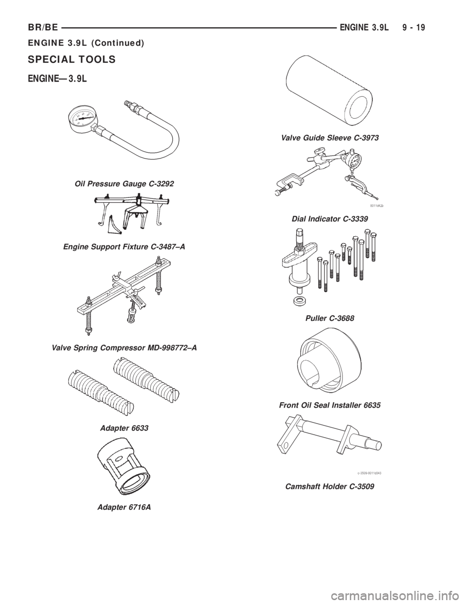
SPECIAL TOOLS
ENGINEÐ3.9L
Oil Pressure Gauge C-3292
Engine Support Fixture C-3487±A
Valve Spring Compressor MD-998772±A
Adapter 6633
Adapter 6716A
Valve Guide Sleeve C-3973
Dial Indicator C-3339
Puller C-3688
Front Oil Seal Installer 6635
Camshaft Holder C-3509
BR/BEENGINE 3.9L 9 - 19
ENGINE 3.9L (Continued)
Page 1167 of 2889
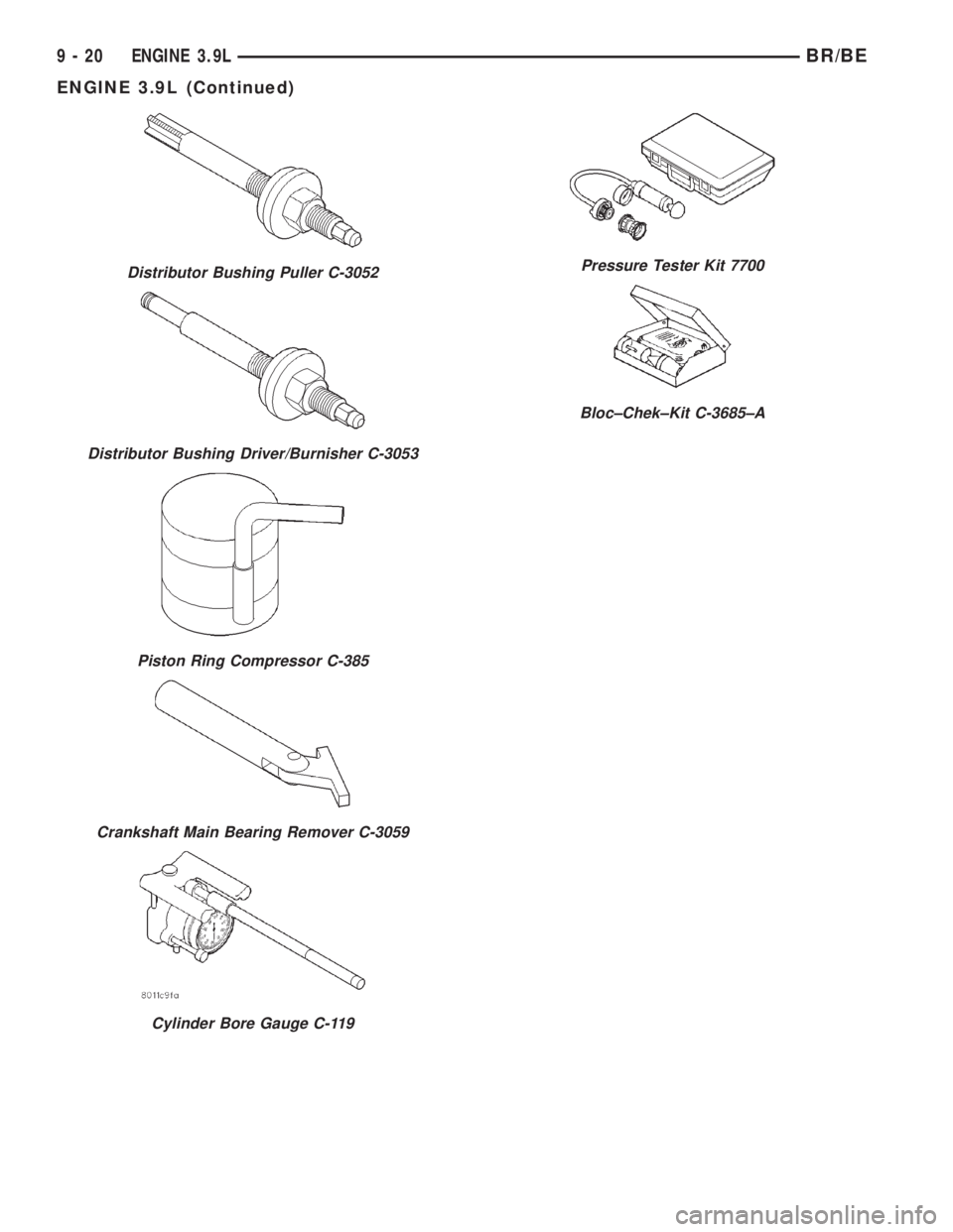
Distributor Bushing Puller C-3052
Distributor Bushing Driver/Burnisher C-3053
Piston Ring Compressor C-385
Crankshaft Main Bearing Remover C-3059
Cylinder Bore Gauge C-119
Pressure Tester Kit 7700
Bloc±Chek±Kit C-3685±A
9 - 20 ENGINE 3.9LBR/BE
ENGINE 3.9L (Continued)
Page 1168 of 2889
AIR CLEANER ELEMENT
REMOVAL - 3.9L/5.2L/5.9L
For air cleaner element required maintenance
schedules (listed in time or mileage intervals), refer
to 0, Lubrication and Maintenance.
CAUTION: Do not attempt to remove air cleaner ele-
ment (filter) from housing by removing top cover
only. To prevent damage to air cleaner housing, the
entire air cleaner housing assembly must be
removed from engine for air cleaner element
replacement.
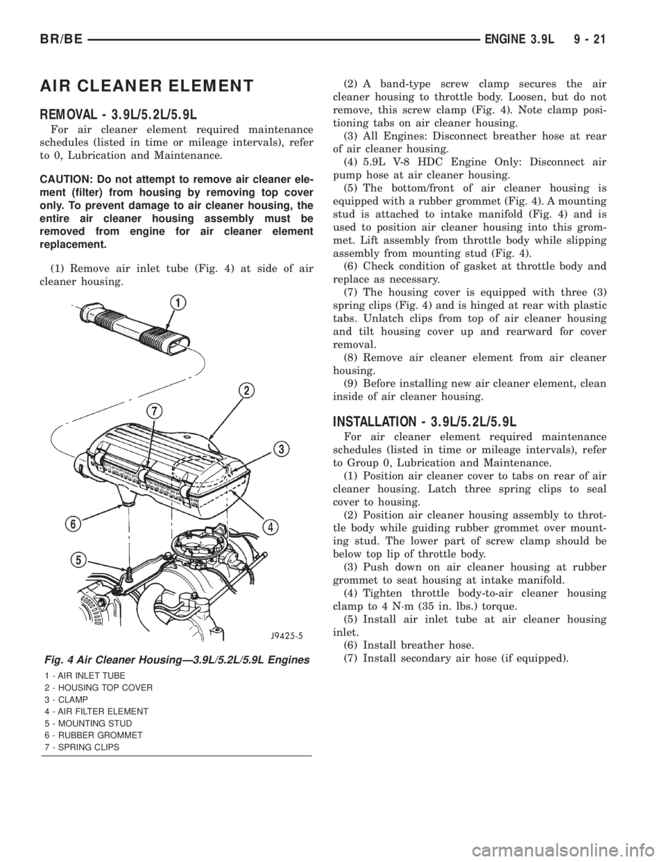
(1) Remove air inlet tube (Fig. 4) at side of air
cleaner housing.(2) A band-type screw clamp secures the air
cleaner housing to throttle body. Loosen, but do not
remove, this screw clamp (Fig. 4). Note clamp posi-
tioning tabs on air cleaner housing.
(3) All Engines: Disconnect breather hose at rear
of air cleaner housing.
(4) 5.9L V-8 HDC Engine Only: Disconnect air
pump hose at air cleaner housing.
(5) The bottom/front of air cleaner housing is
equipped with a rubber grommet (Fig. 4). A mounting
stud is attached to intake manifold (Fig. 4) and is
used to position air cleaner housing into this grom-
met. Lift assembly from throttle body while slipping
assembly from mounting stud (Fig. 4).
(6) Check condition of gasket at throttle body and
replace as necessary.
(7) The housing cover is equipped with three (3)
spring clips (Fig. 4) and is hinged at rear with plastic
tabs. Unlatch clips from top of air cleaner housing
and tilt housing cover up and rearward for cover
removal.
(8) Remove air cleaner element from air cleaner
housing.
(9) Before installing new air cleaner element, clean
inside of air cleaner housing.
INSTALLATION - 3.9L/5.2L/5.9L
For air cleaner element required maintenance
schedules (listed in time or mileage intervals), refer
to Group 0, Lubrication and Maintenance.
(1) Position air cleaner cover to tabs on rear of air
cleaner housing. Latch three spring clips to seal
cover to housing.
(2) Position air cleaner housing assembly to throt-
tle body while guiding rubber grommet over mount-
ing stud. The lower part of screw clamp should be
below top lip of throttle body.
(3) Push down on air cleaner housing at rubber
grommet to seat housing at intake manifold.
(4) Tighten throttle body-to-air cleaner housing
clamp to 4 N´m (35 in. lbs.) torque.
(5) Install air inlet tube at air cleaner housing
inlet.
(6) Install breather hose.
(7) Install secondary air hose (if equipped).
Fig. 4 Air Cleaner HousingÐ3.9L/5.2L/5.9L Engines
1 - AIR INLET TUBE
2 - HOUSING TOP COVER
3 - CLAMP
4 - AIR FILTER ELEMENT
5 - MOUNTING STUD
6 - RUBBER GROMMET
7 - SPRING CLIPS
BR/BEENGINE 3.9L 9 - 21
Page 1169 of 2889
CYLINDER HEAD
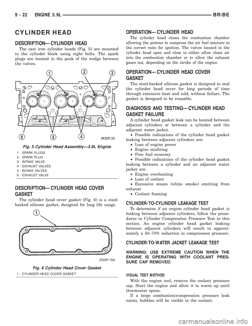
DESCRIPTIONÐCYLINDER HEAD
The cast iron cylinder heads (Fig. 5) are mounted
to the cylinder block using eight bolts. The spark
plugs are located in the peak of the wedge between
the valves.
DESCRIPTIONÐCYLINDER HEAD COVER
GASKET
The cylinder head cover gasket (Fig. 6) is a steel-
backed silicone gasket, designed for long life usage.
OPERATIONÐCYLINDER HEAD
The cylinder head closes the combustion chamber
allowing the pistons to compress the air fuel mixture to
the correct ratio for ignition. The valves located in the
cylinder head open and close to either allow clean air
into the combustion chamber or to allow the exhaust
gases out, depending on the stroke of the engine.
OPERATIONÐCYLINDER HEAD COVER
GASKET
The steel-backed silicone gasket is designed to seal
the cylinder head cover for long periods of time
through extensive heat and cold, without failure. The
gasket is designed to be reusable.
DIAGNOSIS AND TESTINGÐCYLINDER HEAD
GASKET FAILURE
A cylinder head gasket leak can be located between
adjacent cylinders or between a cylinder and the
adjacent water jacket.
²Possible indications of the cylinder head gasket
leaking between adjacent cylinders are:
²Loss of engine power
²Engine misfiring
²Poor fuel economy
²Possible indications of the cylinder head gasket
leaking between a cylinder and an adjacent water
jacket are:
²Engine overheating
²Loss of coolant
²Excessive steam (white smoke) emitting from
exhaust
²Coolant foaming
CYLINDER-TO-CYLINDER LEAKAGE TEST
To determine if an engine cylinder head gasket is
leaking between adjacent cylinders, follow the proce-
dures in Cylinder Compression Pressure Test in this
section. An engine cylinder head gasket leaking
between adjacent cylinders will result in approxi-
mately a 50±70% reduction in compression pressure.
CYLINDER-TO-WATER JACKET LEAKAGE TEST
WARNING: USE EXTREME CAUTION WHEN THE
ENGINE IS OPERATING WITH COOLANT PRES-
SURE CAP REMOVED.
VISUAL TEST METHOD
With the engine cool, remove the coolant pressure
cap. Start the engine and allow it to warm up until
thermostat opens.
If a large combustion/compression pressure leak
exists, bubbles will be visible in the coolant.
Fig. 5 Cylinder Head AssemblyÐ3.9L Engine
1 - SPARK PLUGS
2 - SPARK PLUG
3 - INTAKE VALVE
4 - EXHAUST VALVES
5 - INTAKE VALVES
6 - EXHAUST VALVE
Fig. 6 Cylinder Head Cover Gasket
1 - CYLINDER HEAD COVER GASKET
9 - 22 ENGINE 3.9LBR/BE
Page 1170 of 2889
COOLING SYSTEM TESTER METHOD
WARNING: WITH COOLING SYSTEM TESTER IN
PLACE, PRESSURE WILL BUILD UP FAST. EXCES-
SIVE PRESSURE BUILT UP, BY CONTINUOUS
ENGINE OPERATION, MUST BE RELEASED TO A
SAFE PRESSURE POINT. NEVER PERMIT PRES-
SURE TO EXCEED 138 kPa (20 psi).
Install Cooling System Tester 7700 or equivalent to
pressure cap neck. Start the engine and observe the
tester's pressure gauge. If gauge pulsates with every
power stroke of a cylinder a combustion pressure
leak is evident.
CHEMICAL TEST METHOD
Combustion leaks into the cooling system can also
be checked by using Bloc-Chek Kit C-3685-A or
equivalent. Perform test following the procedures
supplied with the tool kit.
REMOVAL
The alloy cast iron cylinder heads (Fig. 7) are held
in place by eight bolts. The spark plugs are located
at the peak of the wedge between the valves.
(1) Disconnect the battery negative cable from the
battery.
(2) Drain cooling system. (Refer to 7 - COOLING -
STANDARD PROCEDURE).
(3) Remove the intake manifold-to-generator
bracket support rod. Remove the generator.
(4) Remove closed crankcase ventilation system.
(5) Disconnect the evaporation control system.
(6) Remove the air cleaner, air in-let hose and res-
onator.
(7) Perform fuel system pressure release procedure
(Refer to 14 - FUEL SYSTEM/FUEL DELIVERY -
STANDARD PROCEDURE).
(8) Disconnect the fuel supply line from the fuel
rail (Refer to 14 - FUEL SYSTEM/FUEL DELIVERY/
QUICK CONNECT FITTING - STANDARD PROCE-
DURE).
(9) Disconnect accelerator linkage and if so
equipped, the speed control and transmission kick-
down cables.
(10) Remove distributor cap and wires.
(11) Disconnect the coil wires.
(12) Disconnect coolant temperature sending unit
wire.
(13) Disconnect heater hoses and bypass hose.
(14) Disconnect the vacuum supply hoses from the
intake manifold.
(15) Disconnect the fuel injector harness and
secure out of the way.
(16) Remove cylinder head covers and gaskets
(Refer to 9 - ENGINE/CYLINDER HEAD/CYLIN-
DER HEAD COVER(S) - REMOVAL).(17) Remove intake manifold and throttle body as
an assembly. Discard the flange side gaskets and the
front and rear cross-over gaskets.
(18) Remove exhaust manifolds (Refer to 9 -
ENGINE/MANIFOLDS/EXHAUST MANIFOLD -
REMOVAL).
(19) Remove rocker arm assemblies and push rods.
Identify to ensure installation in original locations.
(20) Remove the head bolts from each cylinder
head and remove cylinder heads. Discard the cylin-
der head gasket.
(21) Remove spark plugs.
CLEANING
Clean all surfaces of cylinder block and cylinder
heads.
Clean cylinder block front and rear gasket surfaces
using a suitable solvent.
INSPECTION
Inspect all surfaces with a straightedge if there is
any reason to suspect leakage. If out-of-flatness
exceeds 0.00075mm (0.0001in.) times the span length
in any direction, either replace head or lightly
machine the head surface.
FOR EXAMPLE:ÐA 305 mm (12 in.) span is
0.102 mm (0.004 in.) out-of-flat. The allowable out-of-
flat is 305 x 0.00075 (12 x 0.00075) equals 0.23 mm
(0.009 in.). This amount of out-of-flat is acceptable.
The cylinder head surface finish should be
1.78-3.00 microns (70-125 microinches).
Inspect push rods. Replace worn or bent rods.
INSTALLATION
The alloy cast iron cylinder heads (Fig. 7) are held
in place by eight bolts. The spark plugs are located
at the peak of the wedge between the valves.
(1) Position the new cylinder head gaskets onto
the cylinder block.
(2) Position the cylinder heads onto head gaskets
and cylinder block.
(3) Starting at top center, tighten all cylinder head
bolts, in sequence, to 68 N´m (50 ft. lbs.) torque (Fig.
7). Repeat procedure, tighten all cylinder head bolts
to 143 N´m (105 ft. lbs.) torque. Repeat procedure to
confirm that all bolts are at 143 N´m (105 ft. lbs.)
torque.
CAUTION: When tightening the rocker arm bolts, be
sure the piston in that cylinder is NOT at TDC. Con-
tact between the valves and piston could occur.
(4) Install push rods and rocker arm assemblies in
their original positions. Tighten the bolts to 28 N´m
(21 ft. lbs.) torque.
BR/BEENGINE 3.9L 9 - 23
CYLINDER HEAD (Continued)