DODGE RAM 2001 Service Repair Manual
Manufacturer: DODGE, Model Year: 2001, Model line: RAM, Model: DODGE RAM 2001Pages: 2889, PDF Size: 68.07 MB
Page 1171 of 2889
(5) Install the intake manifold (Refer to 9 -
ENGINE/MANIFOLDS/INTAKE MANIFOLD -
INSTALLATION) and throttle body assembly.
(6) Install exhaust manifolds (Refer to 9 -
ENGINE/MANIFOLDS/EXHAUST MANIFOLD -
INSTALLATION).
(7) Adjust spark plugs to specifications. Install the
plugs and tighten to 41 N´m (30 ft. lbs.) torque.
(8) Install coil wires.
(9) Connect coolant temperature sending unit wire.
(10) Connect the fuel injector harness.
(11) Connect the vacuum supply hoses to the
intake manifold.
(12) Connect the heater hoses and bypass hose.
(13) Install distributor cap and wires.
(14) Connect the accelerator linkage and, if so
equipped, the speed control and transmission kick-
down cables.
(15) Install the fuel supply line.
(16) Install the generator and accessory drive belt
(Refer to 7 - COOLING/ACCESSORY DRIVE/DRIVE
BELTS - INSTALLATION). Tighten generator
mounting bolt to 41 N´m (30 ft. lbs.) torque.
(17) Install the intake manifold-to-generator
bracket support rod. Tighten the bolts.
(18) Install cylinder head covers. (Refer to 9 -
ENGINE/CYLINDER HEAD/CYLINDER HEAD
COVER(S) - INSTALLATION).
(19) Install closed crankcase ventilation system.
(20) Connect the evaporation control system.
(21) Install the resonator assembly, air in-let hose
and air cleaner.
(22) Install the heat shields. Tighten the bolts to
41 N´m (30 ft. lbs.) torque.
(23) Fill cooling system (Refer to 7 - COOLING -
STANDARD PROCEDURE).
(24) Connect the battery negative cable.
CYLINDER HEAD COVER(S)
REMOVAL
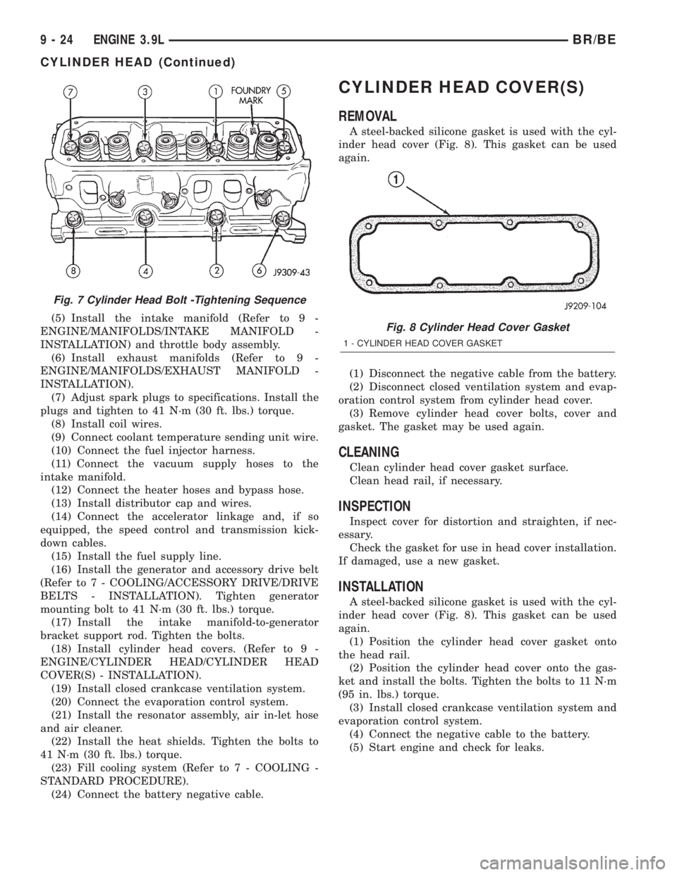
A steel-backed silicone gasket is used with the cyl-
inder head cover (Fig. 8). This gasket can be used
again.
(1) Disconnect the negative cable from the battery.
(2) Disconnect closed ventilation system and evap-
oration control system from cylinder head cover.
(3) Remove cylinder head cover bolts, cover and
gasket. The gasket may be used again.
CLEANING
Clean cylinder head cover gasket surface.
Clean head rail, if necessary.
INSPECTION
Inspect cover for distortion and straighten, if nec-
essary.
Check the gasket for use in head cover installation.
If damaged, use a new gasket.
INSTALLATION
A steel-backed silicone gasket is used with the cyl-
inder head cover (Fig. 8). This gasket can be used
again.
(1) Position the cylinder head cover gasket onto
the head rail.
(2) Position the cylinder head cover onto the gas-
ket and install the bolts. Tighten the bolts to 11 N´m
(95 in. lbs.) torque.
(3) Install closed crankcase ventilation system and
evaporation control system.
(4) Connect the negative cable to the battery.
(5) Start engine and check for leaks.
Fig. 7 Cylinder Head Bolt -Tightening Sequence
Fig. 8 Cylinder Head Cover Gasket
1 - CYLINDER HEAD COVER GASKET
9 - 24 ENGINE 3.9LBR/BE
CYLINDER HEAD (Continued)
Page 1172 of 2889
INTAKE/EXHAUST VALVES &
SEATS
DESCRIPTION
Both the intake and exhaust valves are made of
steel. The intake valve is 48.768 mm (1.92 inches) in
diameter and the exhaust valve is 41.148 mm (1.62
inches) in diameter and has a 2.032 mm (0.080 inch)
wafer interia welded to the tip for durability. These
valves are not splayed.
STANDARD PROCEDUREÐVALVES, GUIDES
AND SPRINGS
VALVE CLEANING
Clean valves thoroughly. Discard burned, warped,
or cracked valves.
Remove carbon and varnish deposits from inside of
valve guides with a reliable guide cleaner.
VALVE GUIDES
Measure valve stems for wear. If wear exceeds
0.051 mm (0.002 in.), replace the valve.
Measure valve stem guide clearance as follows:
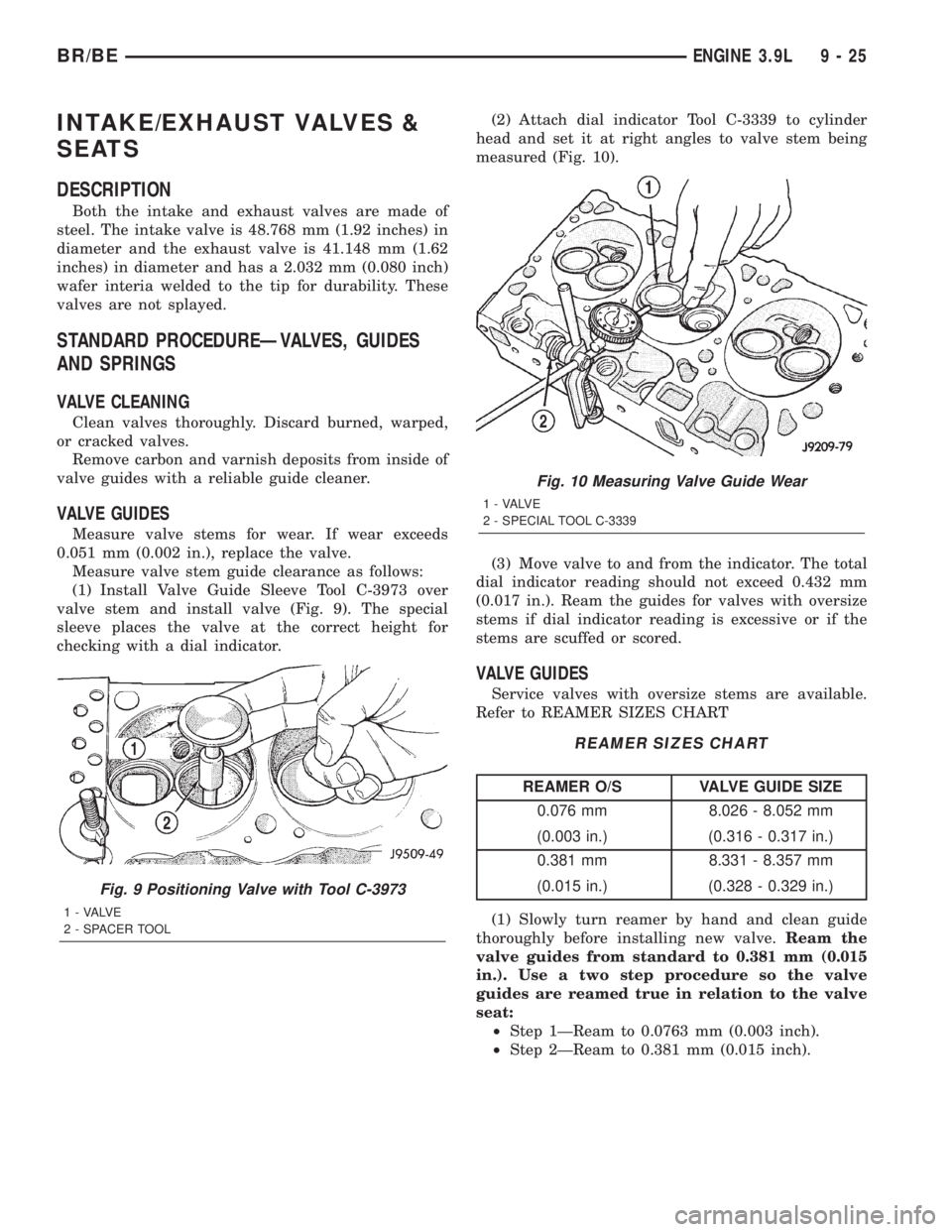
(1) Install Valve Guide Sleeve Tool C-3973 over
valve stem and install valve (Fig. 9). The special
sleeve places the valve at the correct height for
checking with a dial indicator.(2) Attach dial indicator Tool C-3339 to cylinder
head and set it at right angles to valve stem being
measured (Fig. 10).
(3) Move valve to and from the indicator. The total
dial indicator reading should not exceed 0.432 mm
(0.017 in.). Ream the guides for valves with oversize
stems if dial indicator reading is excessive or if the
stems are scuffed or scored.
VALVE GUIDES
Service valves with oversize stems are available.
Refer to REAMER SIZES CHART
REAMER SIZES CHART
REAMER O/S VALVE GUIDE SIZE
0.076 mm 8.026 - 8.052 mm
(0.003 in.) (0.316 - 0.317 in.)
0.381 mm 8.331 - 8.357 mm
(0.015 in.) (0.328 - 0.329 in.)
(1) Slowly turn reamer by hand and clean guide
thoroughly before installing new valve.Ream the
valve guides from standard to 0.381 mm (0.015
in.). Use a two step procedure so the valve
guides are reamed true in relation to the valve
seat:
²Step 1ÐReam to 0.0763 mm (0.003 inch).
²Step 2ÐReam to 0.381 mm (0.015 inch).
Fig. 9 Positioning Valve with Tool C-3973
1 - VALVE
2 - SPACER TOOL
Fig. 10 Measuring Valve Guide Wear
1 - VALVE
2 - SPECIAL TOOL C-3339
BR/BEENGINE 3.9L 9 - 25
Page 1173 of 2889
REFACING VALVES AND VALVE SEATS
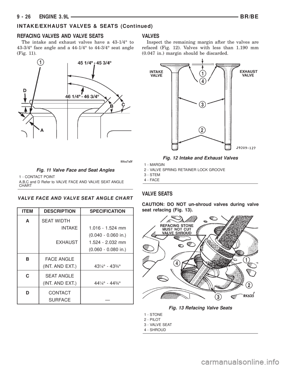
The intake and exhaust valves have a 43-1/4É to
43-3/4É face angle and a 44-1/4É to 44-3/4É seat angle
(Fig. 11).
VALVE FACE AND VALVE SEAT ANGLE CHART
ITEM DESCRIPTION SPECIFICATION
ASEAT WIDTH
INTAKE 1.016 - 1.524 mm
(0.040 - 0.060 in.)
EXHAUST 1.524 - 2.032 mm
(0.060 - 0.080 in.)
BFACE ANGLE
(INT. AND EXT.) 43òÉ - 43ôÉ
CSEAT ANGLE
(INT. AND EXT.) 44òÉ - 44ôÉ
DCONTACT
SURFACE Ð
VALVES
Inspect the remaining margin after the valves are
refaced (Fig. 12). Valves with less than 1.190 mm
(0.047 in.) margin should be discarded.
VALVE SEATS
CAUTION: DO NOT un-shroud valves during valve
seat refacing (Fig. 13).
Fig. 11 Valve Face and Seat Angles
1 - CONTACT POINT
A,B,C and D Refer to VALVE FACE AND VALVE SEAT ANGLE
CHART
Fig. 12 Intake and Exhaust Valves
1 - MARGIN
2 - VALVE SPRING RETAINER LOCK GROOVE
3 - STEM
4-FACE
Fig. 13 Refacing Valve Seats
1-STONE
2 - PILOT
3 - VALVE SEAT
4 - SHROUD
9 - 26 ENGINE 3.9LBR/BE
INTAKE/EXHAUST VALVES & SEATS (Continued)
Page 1174 of 2889
(1) When refacing valve seats, it is important that
the correct size valve guide pilot be used for reseat-
ing stones. A true and complete surface must be
obtained.
(2) Measure the concentricity of valve seat using a
dial indicator. Total runout should not exceed 0.051
mm (0.002 in.) total indicator reading.
(3) Inspect the valve seat with Prussian blue, to
determine where the valve contacts the seat. To do
this, coat valve seat LIGHTLY with Prussian blue
then set valve in place. Rotate the valve with light
pressure. If the blue is transferred to the center of
valve face, contact is satisfactory. If the blue is trans-
ferred to the top edge of valve face, lower valve seat
with a 15É stone. If the blue is transferred to bottom
edge of valve face raise valve seat with a 60É stone.
(4) When seat is properly positioned the width of
intake seats should be 1.016-1.524 mm (0.040-0.060
in.). The width of the exhaust seats should be 1.524-
2.032 mm (0.060-0.080 in.).
VALVE SPRINGS
Whenever valves have been removed for inspection,
reconditioning or replacement, valve springs should
be tested. As an example the compression length of
the spring to be tested is 1-5/16 in.. Turn table of
Universal Valve Spring Tester Tool until surface is in
line with the 1-5/16 in. mark on the threaded stud.
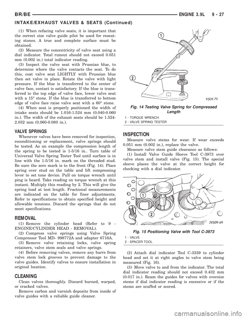
Be sure the zero mark is to the front (Fig. 14). Place
spring over stud on the table and lift compressing
lever to set tone device. Pull on torque wrench until
ping is heard. Take reading on torque wrench at this
instant. Multiply this reading by 2. This will give the
spring load at test length. Fractional measurements
are indicated on the table for finer adjustments.
Refer to specifications to obtain specified height and
allowable tensions. Discard the springs that do not
meet specifications.
REMOVAL
(1) Remove the cylinder head (Refer to 9 -
ENGINE/CYLINDER HEAD - REMOVAL).
(2) Compress valve springs using Valve Spring
Compressor Tool MD- 998772A and adapter 6716A.
(3) Remove valve retaining locks, valve spring
retainers, valve stem seals and valve springs.
(4) Before removing valves, remove any burrs from
valve stem lock grooves to prevent damage to the
valve guides. Identify valves to ensure installation in
original location.
CLEANING
Clean valves thoroughly. Discard burned, warped,
or cracked valves.
Remove carbon and varnish deposits from inside of
valve guides with a reliable guide cleaner.
INSPECTION
Measure valve stems for wear. If wear exceeds
0.051 mm (0.002 in.), replace the valve.
Measure valve stem guide clearance as follows:
(1) Install Valve Guide Sleeve Tool C-3973 over
valve stem and install valve (Fig. 15). The special
sleeve places the valve at the correct height for
checking with a dial indicator.
(2) Attach dial indicator Tool C-3339 to cylinder
head and set it at right angles to valve stem being
measured (Fig. 16).
(3) Move valve to and from the indicator. The total
dial indicator reading should not exceed 0.432 mm
(0.017 in.). Ream the guides for valves with oversize
stems if dial indicator reading is excessive or if the
stems are scuffed or scored.
Fig. 14 Testing Valve Spring for Compressed
Length
1 - TORQUE WRENCH
2 - VALVE SPRING TESTER
Fig. 15 Positioning Valve with Tool C-3973
1 - VALVE
2 - SPACER TOOL
BR/BEENGINE 3.9L 9 - 27
INTAKE/EXHAUST VALVES & SEATS (Continued)
Page 1175 of 2889
INSTALLATION
(1) Clean valves thoroughly. Discard burned,
warped and cracked valves.
(2) Remove carbon and varnish deposits from
inside of valve guides with a reliable guide cleaner.
(3) Measure valve stems for wear. If wear exceeds
0.051 mm (0.002 inch), replace the valve.
(4) Coat valve stems with lubrication oil and insert
them in cylinder head.
(5) If valves or seats are reground, check valve
stem height. If valve is too long, replace cylinder
head.
(6) Install new seals on all valve guides. Install
valve springs and valve retainers.
(7) Compress valve springs with Valve Spring
Compressor Tool MD-998772A and adapter 6716A,
install locks and release tool. If valves and/or seats
are ground, measure the installed height of springs.
Make sure the measurement is taken from bottom of
spring seat in cylinder head to the bottom surface of
spring retainer. If spacers are installed, measure
from the top of spacer. If height is greater than 42.86
mm (1-11/16 inches), install a 1.587 mm (1/16 inch)
spacer in head counterbore. This should bring spring
height back to normal 41.27 to 42.86 mm (1-5/8 to
1-11/16 inch).
(8) Install cylinder head (Refer to 9 - ENGINE/
CYLINDER HEAD - INSTALLATION).
ENGINE BLOCK
CLEANING
Clean cylinder block thoroughly and check all core
hole plugs for evidence of leakage.
INSPECTION
Examine block for cracks or fractures.
The cylinder walls should be checked for out-of-
round and taper. Refer to Honing Cylinder Bores in
the Service Procedures portion of this Section.
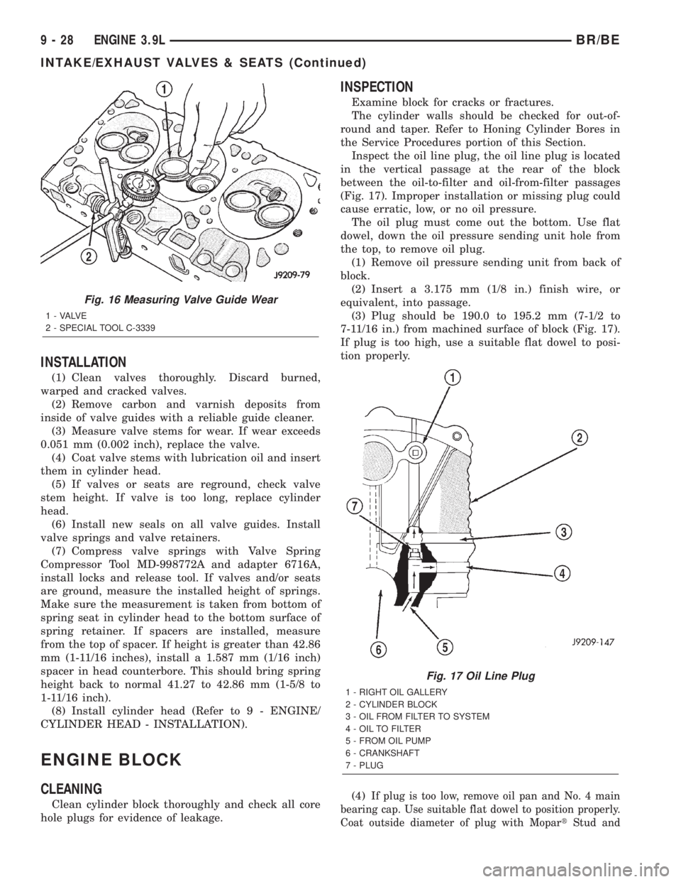
Inspect the oil line plug, the oil line plug is located
in the vertical passage at the rear of the block
between the oil-to-filter and oil-from-filter passages
(Fig. 17). Improper installation or missing plug could
cause erratic, low, or no oil pressure.
The oil plug must come out the bottom. Use flat
dowel, down the oil pressure sending unit hole from
the top, to remove oil plug.
(1) Remove oil pressure sending unit from back of
block.
(2) Insert a 3.175 mm (1/8 in.) finish wire, or
equivalent, into passage.
(3) Plug should be 190.0 to 195.2 mm (7-1/2 to
7-11/16 in.) from machined surface of block (Fig. 17).
If plug is too high, use a suitable flat dowel to posi-
tion properly.
(4)
If plug is too low, remove oil pan and No. 4 main
bearing cap. Use suitable flat dowel to position properly.
Coat outside diameter of plug with MopartStud and
Fig. 16 Measuring Valve Guide Wear
1 - VALVE
2 - SPECIAL TOOL C-3339
Fig. 17 Oil Line Plug
1 - RIGHT OIL GALLERY
2 - CYLINDER BLOCK
3 - OIL FROM FILTER TO SYSTEM
4 - OIL TO FILTER
5 - FROM OIL PUMP
6 - CRANKSHAFT
7 - PLUG
9 - 28 ENGINE 3.9LBR/BE
INTAKE/EXHAUST VALVES & SEATS (Continued)
Page 1176 of 2889
Bearing Mount Adhesive. Plug should be 54.0 to 57.7
mm (2-1/8 to 2-5/16 in.) from bottom of the block.
CAMSHAFT & BEARINGS (IN
BLOCK)
REMOVALÐCAMSHAFT BEARINGS
(1) With engine completely disassembled, drive out
rear cam bearing core hole plug.
(2) Install proper size adapters and horseshoe
washers (part of Camshaft Bearing Remover/Installer
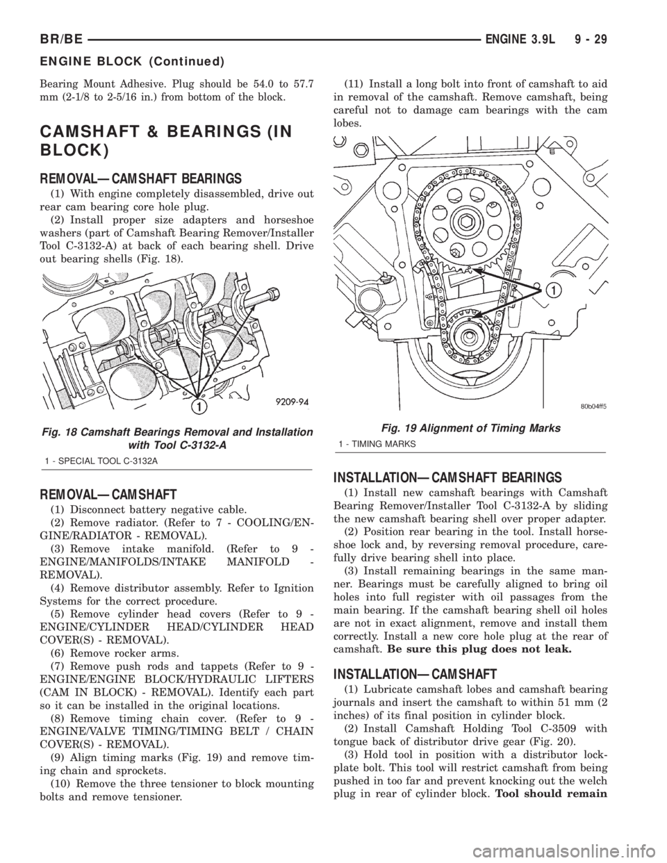
Tool C-3132-A) at back of each bearing shell. Drive
out bearing shells (Fig. 18).
REMOVALÐCAMSHAFT
(1) Disconnect battery negative cable.
(2) Remove radiator. (Refer to 7 - COOLING/EN-
GINE/RADIATOR - REMOVAL).
(3) Remove intake manifold. (Refer to 9 -
ENGINE/MANIFOLDS/INTAKE MANIFOLD -
REMOVAL).
(4) Remove distributor assembly. Refer to Ignition
Systems for the correct procedure.
(5) Remove cylinder head covers (Refer to 9 -
ENGINE/CYLINDER HEAD/CYLINDER HEAD
COVER(S) - REMOVAL).
(6) Remove rocker arms.
(7) Remove push rods and tappets (Refer to 9 -
ENGINE/ENGINE BLOCK/HYDRAULIC LIFTERS
(CAM IN BLOCK) - REMOVAL). Identify each part
so it can be installed in the original locations.
(8) Remove timing chain cover. (Refer to 9 -
ENGINE/VALVE TIMING/TIMING BELT / CHAIN
COVER(S) - REMOVAL).
(9) Align timing marks (Fig. 19) and remove tim-
ing chain and sprockets.
(10) Remove the three tensioner to block mounting
bolts and remove tensioner.(11) Install a long bolt into front of camshaft to aid
in removal of the camshaft. Remove camshaft, being
careful not to damage cam bearings with the cam
lobes.
INSTALLATIONÐCAMSHAFT BEARINGS
(1) Install new camshaft bearings with Camshaft
Bearing Remover/Installer Tool C-3132-A by sliding
the new camshaft bearing shell over proper adapter.
(2) Position rear bearing in the tool. Install horse-
shoe lock and, by reversing removal procedure, care-
fully drive bearing shell into place.
(3) Install remaining bearings in the same man-
ner. Bearings must be carefully aligned to bring oil
holes into full register with oil passages from the
main bearing. If the camshaft bearing shell oil holes
are not in exact alignment, remove and install them
correctly. Install a new core hole plug at the rear of
camshaft.Be sure this plug does not leak.
INSTALLATIONÐCAMSHAFT
(1) Lubricate camshaft lobes and camshaft bearing
journals and insert the camshaft to within 51 mm (2
inches) of its final position in cylinder block.
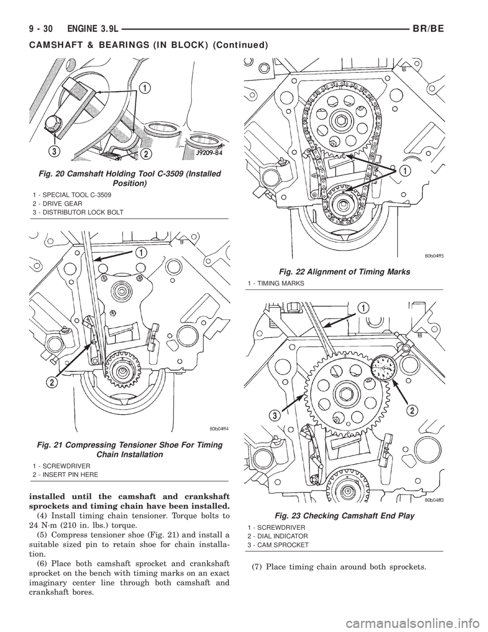
(2) Install Camshaft Holding Tool C-3509 with
tongue back of distributor drive gear (Fig. 20).
(3) Hold tool in position with a distributor lock-
plate bolt. This tool will restrict camshaft from being
pushed in too far and prevent knocking out the welch
plug in rear of cylinder block.Tool should remain
Fig. 18 Camshaft Bearings Removal and Installation
with Tool C-3132-A
1 - SPECIAL TOOL C-3132A
Fig. 19 Alignment of Timing Marks
1 - TIMING MARKS
BR/BEENGINE 3.9L 9 - 29
ENGINE BLOCK (Continued)
Page 1177 of 2889
installed until the camshaft and crankshaft
sprockets and timing chain have been installed.
(4) Install timing chain tensioner. Torque bolts to
24 N´m (210 in. lbs.) torque.
(5) Compress tensioner shoe (Fig. 21) and install a
suitable sized pin to retain shoe for chain installa-
tion.
(6) Place both camshaft sprocket and crankshaft
sprocket on the bench with timing marks on an exact
imaginary center line through both camshaft and
crankshaft bores.(7) Place timing chain around both sprockets.
Fig. 20 Camshaft Holding Tool C-3509 (Installed
Position)
1 - SPECIAL TOOL C-3509
2 - DRIVE GEAR
3 - DISTRIBUTOR LOCK BOLT
Fig. 21 Compressing Tensioner Shoe For Timing
Chain Installation
1 - SCREWDRIVER
2 - INSERT PIN HERE
Fig. 22 Alignment of Timing Marks
1 - TIMING MARKS
Fig. 23 Checking Camshaft End Play
1 - SCREWDRIVER
2 - DIAL INDICATOR
3 - CAM SPROCKET
9 - 30 ENGINE 3.9LBR/BE
CAMSHAFT & BEARINGS (IN BLOCK) (Continued)
Page 1178 of 2889
(8) Turn crankshaft and camshaft to line up with
keyway location in crankshaft sprocket and in cam-
shaft sprocket.
(9) Lift sprockets and chain (keep sprockets tight
against the chain in position as described).
(10) Slide both sprockets evenly over their respec-
tive shafts and use a straightedge to check alignment
of timing marks (Fig. 22).
(11) Install the camshaft bolt/cup washer. Tighten
bolt to 68 N´m (50 ft. lbs.) torque.
(12) Measure camshaft end play (Fig. 23). (Refer to
9 - ENGINE - SPECIFICATIONS) for proper clear-
ance. If not within limits, install a new timing chain
tensioner.
(13) Each tappet reused must be installed in the
same position at which it was removed.When cam-
shaft is replaced, all of the tappets must be
replaced.Install hydraulic tappets (Refer to 9 -
ENGINE/ENGINE BLOCK/HYDRAULIC LIFTERS
(CAM IN BLOCK) - INSTALLATION).
(14) Install timing chain cover (Refer to 9 -
ENGINE/VALVE TIMING/TIMING BELT / CHAIN
COVER(S) - INSTALLATION).
(15) Install intake manifold (Refer to 9 - ENGINE/
MANIFOLDS/INTAKE MANIFOLD - INSTALLA-
TION).
(16) Install distributor.
(17) Install cylinder head covers (Refer to 9 -
ENGINE/CYLINDER HEAD/CYLINDER HEAD
COVER(S) - INSTALLATION).
(18) Install radiator (Refer to 7 - COOLING/EN-
GINE/RADIATOR - INSTALLATION).
(19) Fill cooling system (Refer to 7 - COOLING -
STANDARD PROCEDURE).
(20) Connect battery negative cable.
(21) Start engine and check for leaks.
CONNECTING ROD BEARINGS
STANDARD PROCEDURE-CONNECTING ROD
BEARING FITTING
Fit all rods on a bank until completed. DO NOT
alternate from one bank to another, because connect-
ing rods and pistons are not interchangeable from
one bank to another.
The bearing caps are not interchangeable and
should be marked at removal to ensure correct
assembly.
Each bearing cap has a small V-groove across the
parting face. When installing the lower bearing shell,
be certain that the V-groove in the shell is in line
with the V-groove in the cap. This provides lubrica-
tion of the cylinder wall in the opposite bank.The bearing shells must be installed so that the
tangs are in the machined grooves in the rods and
caps.
Limits of taper or out-of-round on any crankshaft
journals should be held to 0.025 mm (0.001 in.).
Bearings are available in 0.025 mm (0.001 in.), 0.051
mm (0.002 in.), 0.076 mm (0.003 in.), 0.254 mm
(0.010 in.) and 0.305 mm (0.012 in.) undersize.
Install the bearings in pairs. DO NOT use a new
bearing half with an old bearing half. DO NOT
file the rods or bearing caps.
CRANKSHAFT
DESCRIPTION
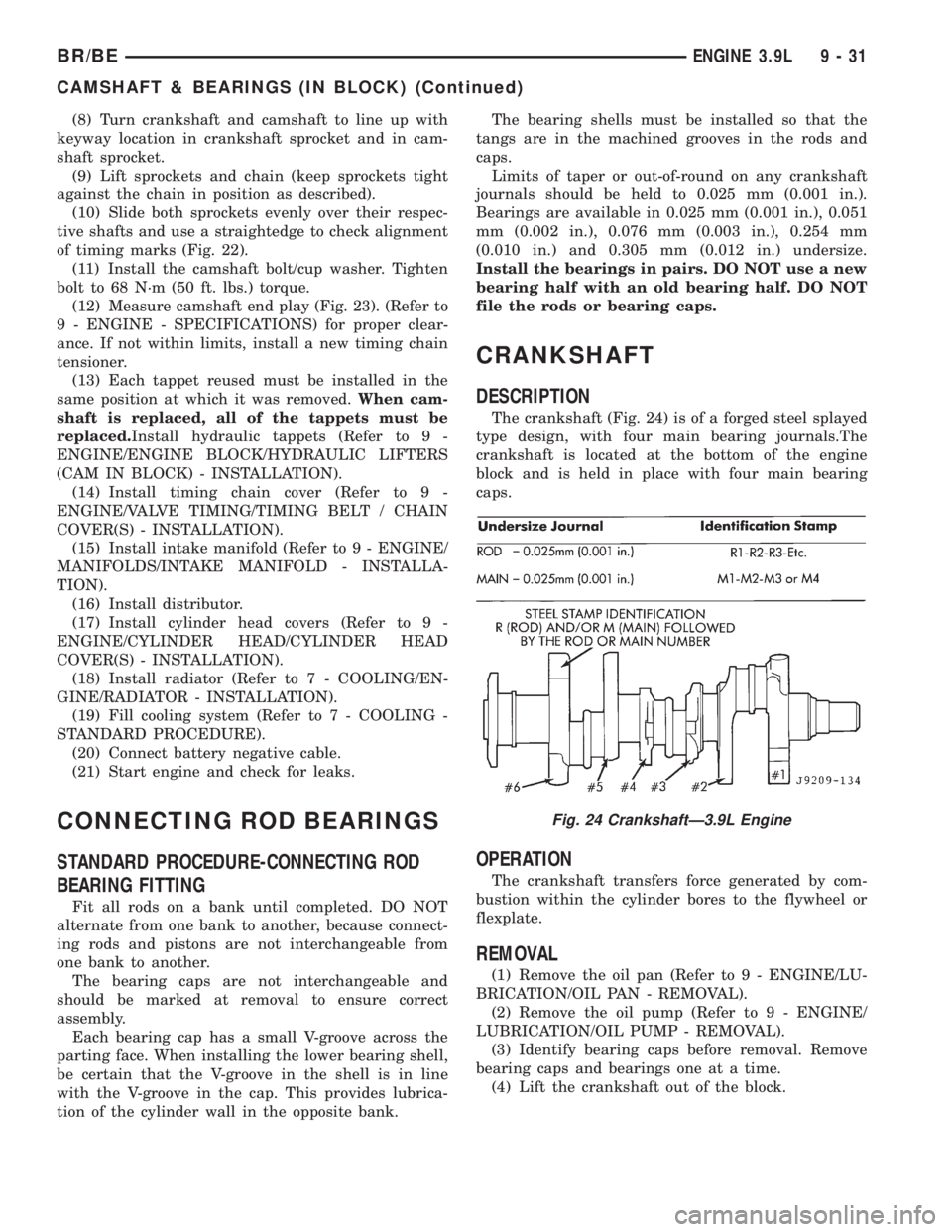
The crankshaft (Fig. 24) is of a forged steel splayed
type design, with four main bearing journals.The
crankshaft is located at the bottom of the engine
block and is held in place with four main bearing
caps.
OPERATION
The crankshaft transfers force generated by com-
bustion within the cylinder bores to the flywheel or
flexplate.
REMOVAL
(1) Remove the oil pan (Refer to 9 - ENGINE/LU-
BRICATION/OIL PAN - REMOVAL).
(2) Remove the oil pump (Refer to 9 - ENGINE/
LUBRICATION/OIL PUMP - REMOVAL).
(3) Identify bearing caps before removal. Remove
bearing caps and bearings one at a time.
(4) Lift the crankshaft out of the block.
Fig. 24 CrankshaftÐ3.9L Engine
BR/BEENGINE 3.9L 9 - 31
CAMSHAFT & BEARINGS (IN BLOCK) (Continued)
Page 1179 of 2889
(5) Remove and discard the crankshaft rear oil
seals.
(6) Remove and discard the front crankshaft oil
seal.
INSTALLATION
(1) Lightly oil the new upper seal lips with engine
oil.
(2) Install the new upper rear bearing oil seal with
the white paint facing towards the rear of the engine.
(3) Position the crankshaft into the cylinder block.
(4) Lightly oil the new lower seal lips with engine
oil.
(5) Install the new lower rear bearing oil seal into
the bearing cap with the white paint facing towards
the rear of the engine.
(6) Apply 5 mm (0.20 in.) drop of Loctite 518, or
equivalent, on each side of the rear main bearing cap
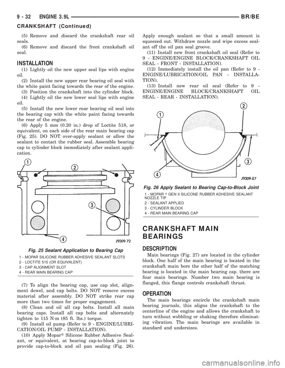
(Fig. 25). DO NOT over-apply sealant or allow the
sealant to contact the rubber seal. Assemble bearing
cap to cylinder block immediately after sealant appli-
cation.
(7) To align the bearing cap, use cap slot, align-
ment dowel, and cap bolts. DO NOT remove excess
material after assembly. DO NOT strike rear cap
more than two times for proper engagement.
(8) Clean and oil all cap bolts. Install all main
bearing caps. Install all cap bolts and alternately
tighten to 115 N´m (85 ft. lbs.) torque.
(9) Install oil pump (Refer to 9 - ENGINE/LUBRI-
CATION/OIL PUMP - INSTALLATION).
(10) Apply MopartSilicone Rubber Adhesive Seal-
ant, or equivalent, at bearing cap-to-block joint to
provide cap-to-block and oil pan sealing (Fig. 26).Apply enough sealant so that a small amount is
squeezed out. Withdraw nozzle and wipe excess seal-
ant off the oil pan seal groove.
(11) Install new front crankshaft oil seal (Refer to
9 - ENGINE/ENGINE BLOCK/CRANKSHAFT OIL
SEAL - FRONT - INSTALLATION).
(12) Immediately install the oil pan (Refer to 9 -
ENGINE/LUBRICATION/OIL PAN - INSTALLA-
TION).
(13) Install new rear oil seal (Refer to 9 -
ENGINE/ENGINE BLOCK/CRANKSHAFT OIL
SEAL - REAR - INSTALLATION).
CRANKSHAFT MAIN
BEARINGS
DESCRIPTION
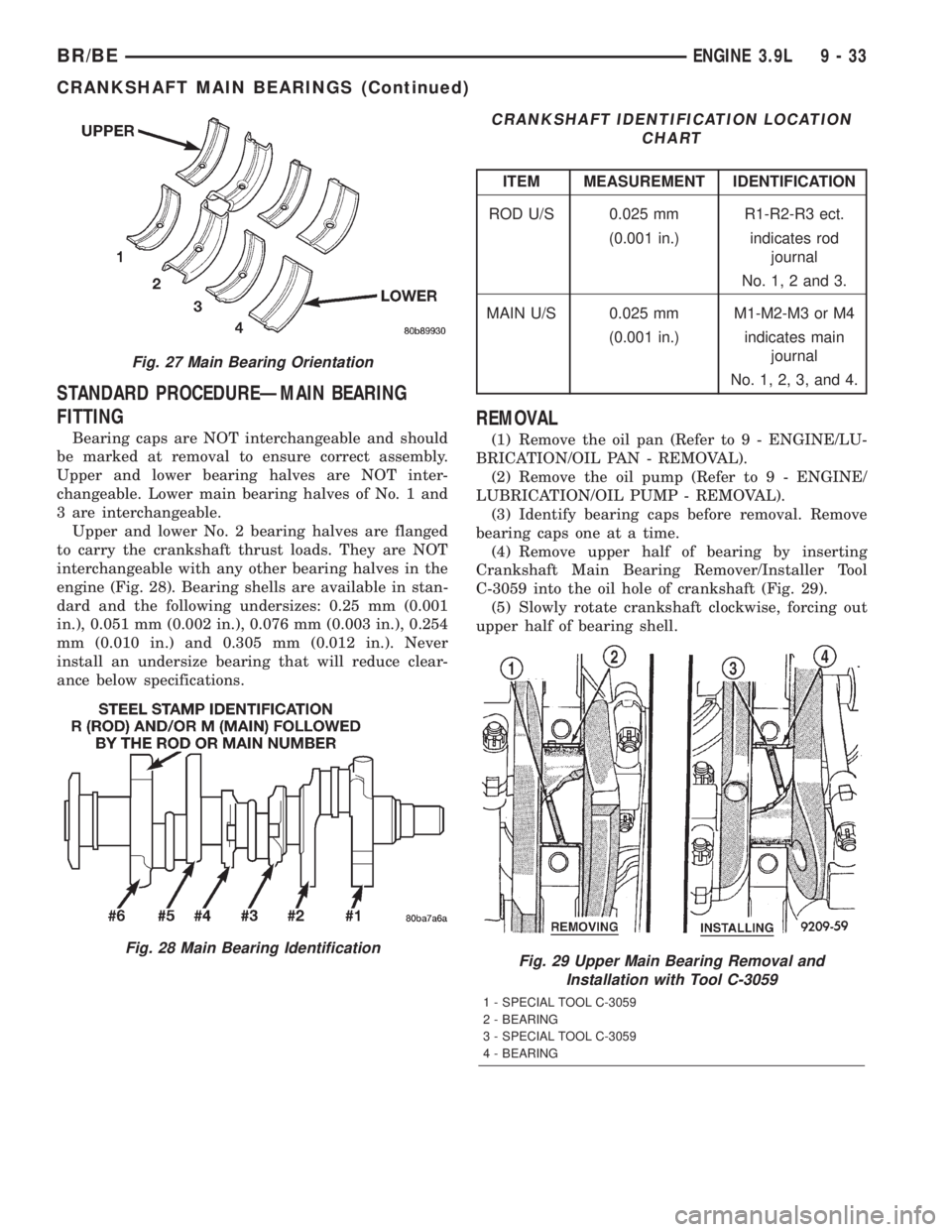
Main bearings (Fig. 27) are located in the cylinder
block. One half of the main bearing is located in the
crankshaft main bore the other half of the matching
bearing is located in the main bearing cap. there are
four main bearings. Number two main bearing is
flanged, this flange controls crankshaft thrust.
OPERATION
The main bearings encircle the crankshaft main
bearing journals, this aligns the crankshaft to the
centerline of the engine and allows the crankshaft to
turn without wobbling or shaking therefore eliminat-
ing vibration. The main bearings are available in
standard and undersizes.
Fig. 25 Sealant Application to Bearing Cap
1 - MOPAR SILICONE RUBBER ADHESIVE SEALANT SLOTS
2 - LOCTITE 515 (OR EQUIVALENT)
3 - CAP ALIGNMENT SLOT
4 - REAR MAIN BEARING CAP
Fig. 26 Apply Sealant to Bearing Cap-to-Block Joint
1 - MOPARTGEN II SILICONE RUBBER ADHESIVE SEALANT
NOZZLE TIP
2 - SEALANT APPLIED
3 - CYLINDER BLOCK
4 - REAR MAIN BEARING CAP
9 - 32 ENGINE 3.9LBR/BE
CRANKSHAFT (Continued)
Page 1180 of 2889
STANDARD PROCEDUREÐMAIN BEARING
FITTING
Bearing caps are NOT interchangeable and should
be marked at removal to ensure correct assembly.
Upper and lower bearing halves are NOT inter-
changeable. Lower main bearing halves of No. 1 and
3 are interchangeable.
Upper and lower No. 2 bearing halves are flanged
to carry the crankshaft thrust loads. They are NOT
interchangeable with any other bearing halves in the
engine (Fig. 28). Bearing shells are available in stan-
dard and the following undersizes: 0.25 mm (0.001
in.), 0.051 mm (0.002 in.), 0.076 mm (0.003 in.), 0.254
mm (0.010 in.) and 0.305 mm (0.012 in.). Never
install an undersize bearing that will reduce clear-
ance below specifications.
CRANKSHAFT IDENTIFICATION LOCATION
CHART
ITEM MEASUREMENT IDENTIFICATION
ROD U/S 0.025 mm R1-R2-R3 ect.
(0.001 in.) indicates rod
journal
No. 1, 2 and 3.
MAIN U/S 0.025 mm M1-M2-M3 or M4
(0.001 in.) indicates main
journal
No. 1, 2, 3, and 4.
REMOVAL
(1) Remove the oil pan (Refer to 9 - ENGINE/LU-
BRICATION/OIL PAN - REMOVAL).
(2) Remove the oil pump (Refer to 9 - ENGINE/
LUBRICATION/OIL PUMP - REMOVAL).
(3) Identify bearing caps before removal. Remove
bearing caps one at a time.
(4) Remove upper half of bearing by inserting
Crankshaft Main Bearing Remover/Installer Tool
C-3059 into the oil hole of crankshaft (Fig. 29).
(5) Slowly rotate crankshaft clockwise, forcing out
upper half of bearing shell.
Fig. 27 Main Bearing Orientation
Fig. 28 Main Bearing IdentificationFig. 29 Upper Main Bearing Removal and
Installation with Tool C-3059
1 - SPECIAL TOOL C-3059
2 - BEARING
3 - SPECIAL TOOL C-3059
4 - BEARING
BR/BEENGINE 3.9L 9 - 33
CRANKSHAFT MAIN BEARINGS (Continued)