DODGE RAM 2001 Service Repair Manual
Manufacturer: DODGE, Model Year: 2001, Model line: RAM, Model: DODGE RAM 2001Pages: 2889, PDF Size: 68.07 MB
Page 681 of 2889
(9) Turn the ignition switch to the Off position for
about fifteen seconds, and then back to the On posi-
tion. Observe the airbag indicator in the instrument
cluster. It should light for six to eight seconds, and
then go out. This indicates that the airbag system is
functioning normally and that the repairs are com-
plete. If the airbag indicator fails to light, or lights
and stays on, there is still an active airbag system
fault or malfunction. Refer to the appropriate diag-
nostic information to diagnose the problem.
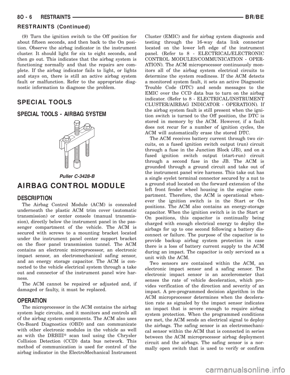
SPECIAL TOOLS
SPECIAL TOOLS - AIRBAG SYSTEM
AIRBAG CONTROL MODULE
DESCRIPTION
The Airbag Control Module (ACM) is concealed
underneath the plastic ACM trim cover (automatic
transmission) or center console (manual transmis-
sion), directly below the instrument panel in the pas-
senger compartment of the vehicle. The ACM is
secured with screws to a mounting bracket located
under the instrument panel center support bracket
on the floor panel transmission tunnel. The ACM
contains an electronic microprocessor, an electronic
impact sensor, an electromechanical safing sensor,
and an energy storage capacitor. The ACM is con-
nected to the vehicle electrical system through a take
out and connector of the instrument panel wire har-
ness.
The ACM cannot be repaired or adjusted and, if
damaged or faulty, it must be replaced.
OPERATION
The microprocessor in the ACM contains the airbag
system logic circuits, and it monitors and controls all
of the airbag system components. The ACM also uses
On-Board Diagnostics (OBD) and can communicate
with other electronic modules in the vehicle as well
as with the DRBIIItscan tool using the Chrysler
Collision Detection (CCD) data bus network. This
method of communication is used for control of the
airbag indicator in the ElectroMechanical InstrumentCluster (EMIC) and for airbag system diagnosis and
testing through the 16-way data link connector
located on the lower left edge of the instrument
panel. (Refer to 8 - ELECTRICAL/ELECTRONIC
CONTROL MODULES/COMMUNICATION - OPER-
ATION). The ACM microprocessor continuously mon-
itors all of the airbag system electrical circuits to
determine the system readiness. If the ACM detects
a monitored system fault, it sets an active Diagnostic
Trouble Code (DTC) and sends messages to the
EMIC over the CCD data bus to turn on the airbag
indicator. (Refer to 8 - ELECTRICAL/INSTRUMENT
CLUSTER/AIRBAG INDICATOR - OPERATION). If
the airbag system fault is still present when the igni-
tion switch is turned to the Off position, the DTC is
stored in memory by the ACM. However, if a fault
does not recur for a number of ignition cycles, the
ACM will automatically erase the stored DTC.
The ACM receives battery current through two cir-
cuits, on a fused ignition switch output (run) circuit
through a fuse in the Junction Block (JB), and on a
fused ignition switch output (start-run) circuit
through a second fuse in the JB. The ACM is
grounded through a ground circuit and take out of
the instrument panel wire harness. This take out has
a single eyelet terminal connector secured by a nut to
a ground stud located on the forward extension of the
left front fender wheel housing in the engine com-
partment. Therefore, the ACM is operational when-
ever the ignition switch is in the Start or On
positions. The ACM also contains an energy-storage
capacitor. When the ignition switch is in the Start or
On positions, this capacitor is continually being
charged with enough electrical energy to deploy the
airbags for up to one second following a battery dis-
connect or failure. The purpose of the capacitor is to
provide backup airbag system protection in case
there is a loss of battery current supply to the ACM
during an impact. The capacitor is only serviced as a
unit with the ACM.
Two sensors are contained within the ACM, an
electronic impact sensor and a safing sensor. The
electronic impact sensor is an accelerometer that
senses the rate of vehicle deceleration, which pro-
vides verification of the direction and severity of an
impact. A pre-programmed decision algorithm in the
ACM microprocessor determines when the decelera-
tion rate as signaled by the impact sensor indicates
an impact that is severe enough to require airbag
system protection. When the programmed conditions
are met, the ACM sends an electrical signal to deploy
the airbags. The safing sensor is an electromechani-
cal sensor within the ACM that is connected in series
between the ACM microprocessor airbag deployment
circuit and the airbags. The safing sensor is a nor-
mally open switch that is used to verify or confirm
Puller C-3428-B
8O - 6 RESTRAINTSBR/BE
RESTRAINTS (Continued)
Page 682 of 2889
the need for an airbag deployment by detecting
impact energy of a lesser magnitude than that of the
electronic impact sensor, and must be closed in order
for the airbags to deploy. The impact sensor and saf-
ing sensor are calibrated for the specific vehicle, and
are only serviced as a unit with the ACM.
REMOVAL
WARNING: DISABLE THE AIRBAG SYSTEM
BEFORE ATTEMPTING ANY STEERING WHEEL,
STEERING COLUMN, OR INSTRUMENT PANEL
COMPONENT DIAGNOSIS OR SERVICE. DISCON-
NECT AND ISOLATE THE BATTERY NEGATIVE
(GROUND) CABLE, THEN WAIT TWO MINUTES FOR
THE AIRBAG SYSTEM CAPACITOR TO DISCHARGE
BEFORE PERFORMING FURTHER DIAGNOSIS OR
SERVICE. THIS IS THE ONLY SURE WAY TO DIS-
ABLE THE AIRBAG SYSTEM. FAILURE TO TAKE
THE PROPER PRECAUTIONS COULD RESULT IN
ACCIDENTAL AIRBAG DEPLOYMENT AND POSSI-
BLE PERSONAL INJURY.
WARNING: THE AIRBAG CONTROL MODULE CON-
TAINS THE IMPACT SENSOR, WHICH ENABLES
THE SYSTEM TO DEPLOY THE AIRBAGS. NEVER
STRIKE OR KICK THE AIRBAG CONTROL MODULE,
AS IT CAN DAMAGE THE IMPACT SENSOR OR
AFFECT ITS CALIBRATION. IF AN AIRBAG CON-
TROL MODULE IS ACCIDENTALLY DROPPED DUR-
ING SERVICE, THE MODULE MUST BE SCRAPPED
AND REPLACED WITH A NEW UNIT. FAILURE TO
OBSERVE THIS WARNING COULD RESULT IN ACCI-
DENTAL, INCOMPLETE, OR IMPROPER AIRBAG
DEPLOYMENT AND POSSIBLE OCCUPANT INJU-
RIES.
(1) Disconnect and isolate the battery negative
cable. If either of the airbags has not been deployed,
wait two minutes for the system capacitor to dis-
charge before further service.
(2) If the vehicle is equipped with a manual trans-
mission, remove the center floor console from the
floor panel transmission tunnel. (Refer to 23 - BODY/
INTERIOR/CENTER CONSOLE - REMOVAL).
(3) If the vehicle is equipped with an automatic
transmission, remove the two screws that secure the
trim cover to the Airbag Control Module (ACM)
mounting bracket on the floor panel transmission
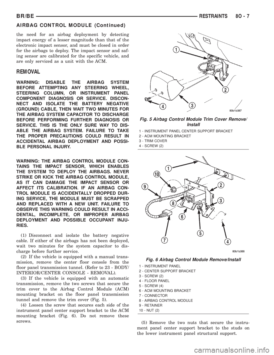
tunnel and remove the trim cover (Fig. 5).
(4) Loosen the screw that secures each side of the
instrument panel center support bracket to the ACM
mounting bracket (Fig. 6). Do not remove these
screws.
(5) Remove the two nuts that secure the instru-
ment panel center support bracket to the studs on
the lower instrument panel structural support.
Fig. 5 Airbag Control Module Trim Cover Remove/
Install
1 - INSTRUMENT PANEL CENTER SUPPORT BRACKET
2 - ACM MOUNTING BRACKET
3 - TRIM COVER
4 - SCREW (2)
Fig. 6 Airbag Control Module Remove/Install
1 - INSTRUMENT PANEL
2 - CENTER SUPPORT BRACKET
3 - SCREW (2)
4 - FLOOR PANEL
5 - SCREW (4)
6 - ACM MOUNTING BRACKET
7 - CONNECTOR
8 - AIRBAG CONTROL MODULE
9 - RETAINER
10 - NUT (2)
BR/BERESTRAINTS 8O - 7
AIRBAG CONTROL MODULE (Continued)
Page 683 of 2889
(6) Disengage the retainer on the instrument
panel wire harness take out to the ACM from the
retainer hole in the left side of the instrument panel
center support bracket.
(7) Pull the top of the instrument panel center
support bracket rearward and down from the instru-
ment panel studs. Fold it down over the top of the
ACM until it is laying flat on the floor panel trans-
mission tunnel.
(8) Disconnect the instrument panel wire harness
connector for the ACM from the ACM connector
receptacle. To disconnect this connector:
(a) Slide the red Connector Position Assurance
(CPA) lock on the top of the connector toward the
side of the vehicle.
(b) Depress the connector latch tab and pull the
connector straight away from the ACM connector
receptacle.
NOTE: Always remove and replace the ACM and its
mounting bracket as a unit. Replacement modules
include a replacement mounting bracket. Do not
transfer the ACM to another mounting bracket.
(9) Remove the four screws that secure the ACM
mounting bracket to the floor panel transmission
tunnel.
(10) Remove the ACM, the mounting bracket, and
the instrument panel center support bracket from the
floor panel transmission tunnel as a unit.
INSTALLATION
WARNING: DISABLE THE AIRBAG SYSTEM
BEFORE ATTEMPTING ANY STEERING WHEEL,
STEERING COLUMN, OR INSTRUMENT PANEL
COMPONENT DIAGNOSIS OR SERVICE. DISCON-
NECT AND ISOLATE THE BATTERY NEGATIVE
(GROUND) CABLE, THEN WAIT TWO MINUTES FOR
THE AIRBAG SYSTEM CAPACITOR TO DISCHARGE
BEFORE PERFORMING FURTHER DIAGNOSIS OR
SERVICE. THIS IS THE ONLY SURE WAY TO DIS-
ABLE THE AIRBAG SYSTEM. FAILURE TO TAKE
THE PROPER PRECAUTIONS COULD RESULT IN
ACCIDENTAL AIRBAG DEPLOYMENT AND POSSI-
BLE PERSONAL INJURY.
WARNING: THE AIRBAG CONTROL MODULE CON-
TAINS THE IMPACT SENSOR, WHICH ENABLES
THE SYSTEM TO DEPLOY THE AIRBAGS. NEVER
STRIKE OR KICK THE AIRBAG CONTROL MODULE,
AS IT CAN DAMAGE THE IMPACT SENSOR OR
AFFECT ITS CALIBRATION. IF AN AIRBAG CON-
TROL MODULE IS ACCIDENTALLY DROPPED DUR-
ING SERVICE, THE MODULE MUST BE SCRAPPED
AND REPLACED WITH A NEW UNIT. FAILURE TOOBSERVE THIS WARNING COULD RESULT IN ACCI-
DENTAL, INCOMPLETE, OR IMPROPER AIRBAG
DEPLOYMENT AND POSSIBLE OCCUPANT INJU-
RIES.
(1) Carefully position the Airbag Control Module
(ACM), the mounting bracket, and the instrument
panel center support bracket onto the floor panel
transmission tunnel as a unit (Fig. 6). When the
ACM is correctly positioned, the arrow on the ACM
label will be pointed forward in the vehicle.
(2) Install and tighten the four screws that secure
the ACM mounting bracket to the floor panel trans-
mission tunnel. Tighten the screws to 14 N´m (125
in. lbs.).
(3) With the instrument panel center support
bracket still folded down flat on the floor panel trans-
mission tunnel, reconnect the instrument panel wire
harness connector for the ACM to the ACM connector
receptacle. Be certain that the connector latch and
the red Connector Position Assurance (CPA) lock are
fully engaged.
(4) Fold the top of the instrument panel center
support bracket up over the top of the ACM and for-
ward over the studs on the lower instrument panel
structural support.
(5) Install and tighten the nuts that secure the
instrument panel center support bracket to the studs
on the lower instrument panel structural support.
Tighten the nuts to 14 N´m (125 in. lbs.).
(6) Engage the retainer on the instrument panel
wire harness take out for the ACM in the retainer
hole on the left side of the instrument panel center
support bracket.
(7) Tighten the screws that secure each side of the
instrument panel center support bracket to the ACM
mounting bracket. Tighten the screws 14 N´m (125
in. lbs.).
(8) If the vehicle is equipped with an automatic
transmission, position the ACM trim cover to the
ACM mounting bracket on the floor panel transmis-
sion tunnel (Fig. 5).
(9) If the vehicle is equipped with an automatic
transmission, install and tighten the two screws that
secure the ACM trim cover to the ACM mounting
bracket. Tighten the screws to 2.2 N´m (20 in. lbs.).
(10) If the vehicle is equipped with a manual
transmission, reinstall the center floor console onto
the floor panel transmission tunnel. (Refer to 23 -
BODY/INTERIOR/CENTER CONSOLE - INSTALLA-
TION).
(11) Do not reconnect the battery negative cable at
this time. The airbag system verification test proce-
dure should be performed following service of any
airbag system component. (Refer to 8 - ELECTRI-
CAL/RESTRAINTS - STANDARD PROCEDURE -
VERIFICATION TEST).
8O - 8 RESTRAINTSBR/BE
AIRBAG CONTROL MODULE (Continued)
Page 684 of 2889
CHILD TETHER
REMOVAL
Standard cab models have two child tether anchors
secured near the top of the cab back panel. Club cab
and quad cab models have three child tethers
secured near the top of the cab back panel.
WARNING: DURING AND FOLLOWING ANY SEAT
BELT SERVICE, CAREFULLY INSPECT ALL SEAT
BELTS, BUCKLES, MOUNTING HARDWARE, AND
RETRACTORS FOR PROPER INSTALLATION,
OPERATION, OR DAMAGE. REPLACE ANY BELT
THAT IS CUT, FRAYED, OR TORN. STRAIGHTEN
ANY BELT THAT IS TWISTED. TIGHTEN ANY
LOOSE FASTENERS. REPLACE ANY BELT THAT
HAS A DAMAGED OR INOPERATIVE BUCKLE OR
RETRACTOR. REPLACE ANY BELT THAT HAS A
BENT OR DAMAGED LATCH PLATE OR ANCHOR
PLATE. NEVER ATTEMPT TO REPAIR A SEAT BELT
COMPONENT. ALWAYS REPLACE DAMAGED OR
FAULTY SEAT BELT COMPONENTS WITH THE COR-
RECT, NEW AND UNUSED REPLACEMENT PARTS
LISTED IN THE MOPAR PARTS CATALOG.
(1) Remove the trim from the inside of the cab
back panel. (Refer to 23 - BODY/INTERIOR/REAR
CLOSURE PANEL TRIM - REMOVAL).(2) Remove the screw that secures the child tether
anchor (standard cab) or child tether (club/quad cab)
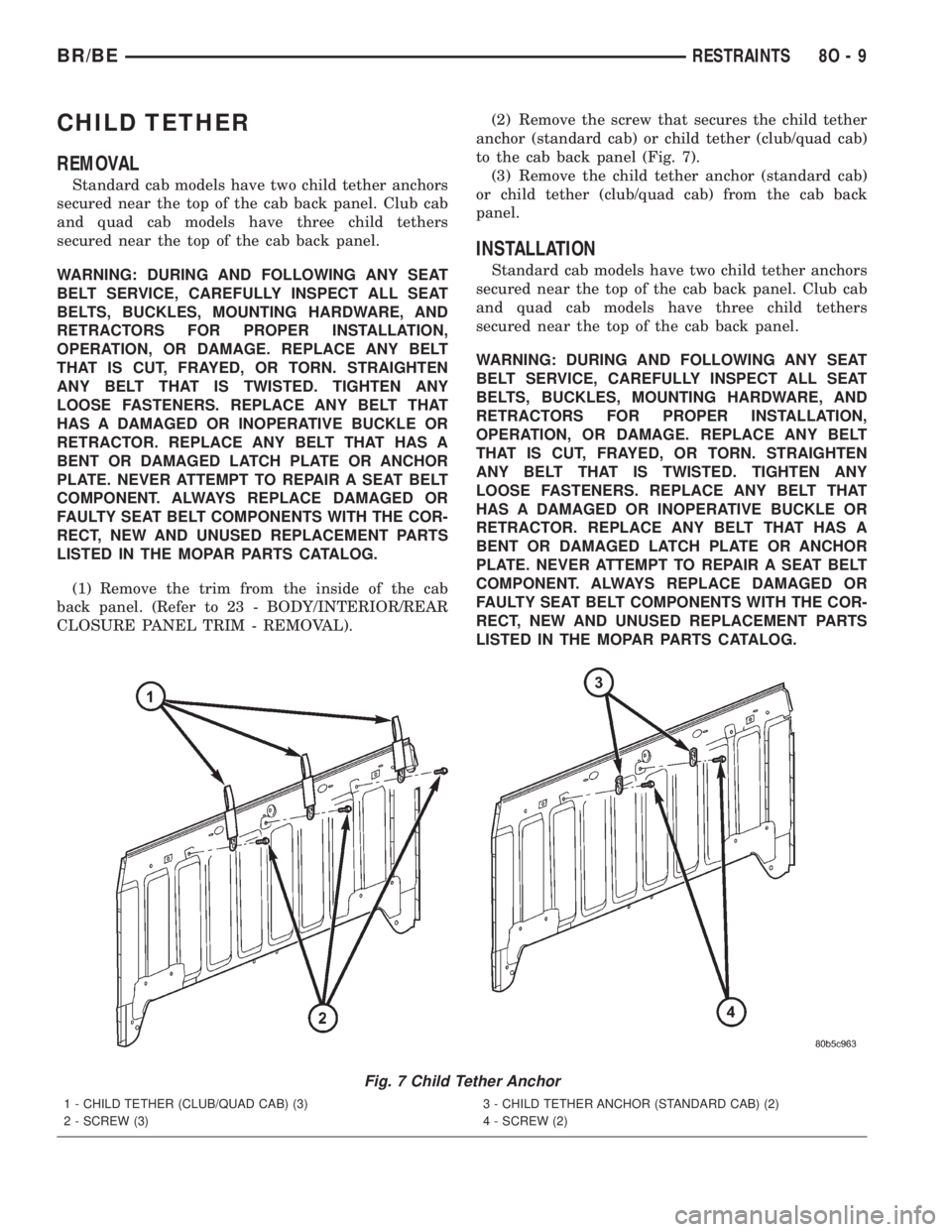
to the cab back panel (Fig. 7).
(3) Remove the child tether anchor (standard cab)
or child tether (club/quad cab) from the cab back
panel.
INSTALLATION
Standard cab models have two child tether anchors
secured near the top of the cab back panel. Club cab
and quad cab models have three child tethers
secured near the top of the cab back panel.
WARNING: DURING AND FOLLOWING ANY SEAT
BELT SERVICE, CAREFULLY INSPECT ALL SEAT
BELTS, BUCKLES, MOUNTING HARDWARE, AND
RETRACTORS FOR PROPER INSTALLATION,
OPERATION, OR DAMAGE. REPLACE ANY BELT
THAT IS CUT, FRAYED, OR TORN. STRAIGHTEN
ANY BELT THAT IS TWISTED. TIGHTEN ANY
LOOSE FASTENERS. REPLACE ANY BELT THAT
HAS A DAMAGED OR INOPERATIVE BUCKLE OR
RETRACTOR. REPLACE ANY BELT THAT HAS A
BENT OR DAMAGED LATCH PLATE OR ANCHOR
PLATE. NEVER ATTEMPT TO REPAIR A SEAT BELT
COMPONENT. ALWAYS REPLACE DAMAGED OR
FAULTY SEAT BELT COMPONENTS WITH THE COR-
RECT, NEW AND UNUSED REPLACEMENT PARTS
LISTED IN THE MOPAR PARTS CATALOG.
Fig. 7 Child Tether Anchor
1 - CHILD TETHER (CLUB/QUAD CAB) (3)
2 - SCREW (3)3 - CHILD TETHER ANCHOR (STANDARD CAB) (2)
4 - SCREW (2)
BR/BERESTRAINTS 8O - 9
Page 685 of 2889
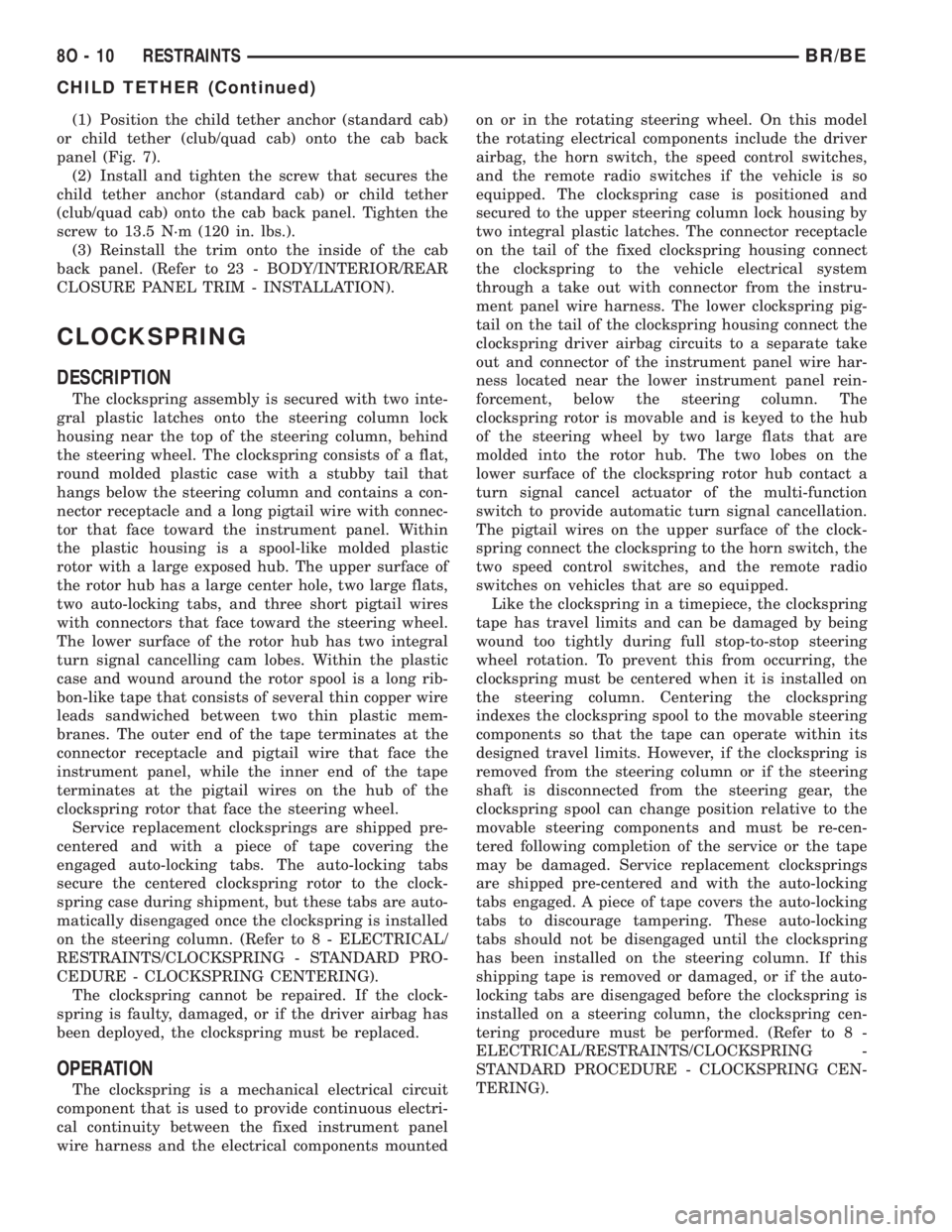
(1) Position the child tether anchor (standard cab)
or child tether (club/quad cab) onto the cab back
panel (Fig. 7).
(2) Install and tighten the screw that secures the
child tether anchor (standard cab) or child tether
(club/quad cab) onto the cab back panel. Tighten the
screw to 13.5 N´m (120 in. lbs.).
(3) Reinstall the trim onto the inside of the cab
back panel. (Refer to 23 - BODY/INTERIOR/REAR
CLOSURE PANEL TRIM - INSTALLATION).
CLOCKSPRING
DESCRIPTION
The clockspring assembly is secured with two inte-
gral plastic latches onto the steering column lock
housing near the top of the steering column, behind
the steering wheel. The clockspring consists of a flat,
round molded plastic case with a stubby tail that
hangs below the steering column and contains a con-
nector receptacle and a long pigtail wire with connec-
tor that face toward the instrument panel. Within
the plastic housing is a spool-like molded plastic
rotor with a large exposed hub. The upper surface of
the rotor hub has a large center hole, two large flats,
two auto-locking tabs, and three short pigtail wires
with connectors that face toward the steering wheel.
The lower surface of the rotor hub has two integral
turn signal cancelling cam lobes. Within the plastic
case and wound around the rotor spool is a long rib-
bon-like tape that consists of several thin copper wire
leads sandwiched between two thin plastic mem-
branes. The outer end of the tape terminates at the
connector receptacle and pigtail wire that face the
instrument panel, while the inner end of the tape
terminates at the pigtail wires on the hub of the
clockspring rotor that face the steering wheel.
Service replacement clocksprings are shipped pre-
centered and with a piece of tape covering the
engaged auto-locking tabs. The auto-locking tabs
secure the centered clockspring rotor to the clock-
spring case during shipment, but these tabs are auto-
matically disengaged once the clockspring is installed
on the steering column. (Refer to 8 - ELECTRICAL/
RESTRAINTS/CLOCKSPRING - STANDARD PRO-
CEDURE - CLOCKSPRING CENTERING).
The clockspring cannot be repaired. If the clock-
spring is faulty, damaged, or if the driver airbag has
been deployed, the clockspring must be replaced.
OPERATION
The clockspring is a mechanical electrical circuit
component that is used to provide continuous electri-
cal continuity between the fixed instrument panel
wire harness and the electrical components mountedon or in the rotating steering wheel. On this model
the rotating electrical components include the driver
airbag, the horn switch, the speed control switches,
and the remote radio switches if the vehicle is so
equipped. The clockspring case is positioned and
secured to the upper steering column lock housing by
two integral plastic latches. The connector receptacle
on the tail of the fixed clockspring housing connect
the clockspring to the vehicle electrical system
through a take out with connector from the instru-
ment panel wire harness. The lower clockspring pig-
tail on the tail of the clockspring housing connect the
clockspring driver airbag circuits to a separate take
out and connector of the instrument panel wire har-
ness located near the lower instrument panel rein-
forcement, below the steering column. The
clockspring rotor is movable and is keyed to the hub
of the steering wheel by two large flats that are
molded into the rotor hub. The two lobes on the
lower surface of the clockspring rotor hub contact a
turn signal cancel actuator of the multi-function
switch to provide automatic turn signal cancellation.
The pigtail wires on the upper surface of the clock-
spring connect the clockspring to the horn switch, the
two speed control switches, and the remote radio
switches on vehicles that are so equipped.
Like the clockspring in a timepiece, the clockspring
tape has travel limits and can be damaged by being
wound too tightly during full stop-to-stop steering
wheel rotation. To prevent this from occurring, the
clockspring must be centered when it is installed on
the steering column. Centering the clockspring
indexes the clockspring spool to the movable steering
components so that the tape can operate within its
designed travel limits. However, if the clockspring is
removed from the steering column or if the steering
shaft is disconnected from the steering gear, the
clockspring spool can change position relative to the
movable steering components and must be re-cen-
tered following completion of the service or the tape
may be damaged. Service replacement clocksprings
are shipped pre-centered and with the auto-locking
tabs engaged. A piece of tape covers the auto-locking
tabs to discourage tampering. These auto-locking
tabs should not be disengaged until the clockspring
has been installed on the steering column. If this
shipping tape is removed or damaged, or if the auto-
locking tabs are disengaged before the clockspring is
installed on a steering column, the clockspring cen-
tering procedure must be performed. (Refer to 8 -
ELECTRICAL/RESTRAINTS/CLOCKSPRING -
STANDARD PROCEDURE - CLOCKSPRING CEN-
TERING).
8O - 10 RESTRAINTSBR/BE
CHILD TETHER (Continued)
Page 686 of 2889
STANDARD PROCEDURE - CLOCKSPRING
CENTERING
The clockspring is designed to wind and unwind
when the steering wheel is rotated, but is only
designed to rotate the same number of turns (about
five complete rotations) as the steering wheel can be
turned from stop to stop. Centering the clockspring
indexes the clockspring tape to other steering compo-
nents so that it can operate within its designed
travel limits. The rotor of a centered clockspring can
be rotated two and one-half turns in either direction
from the centered position, without damaging the
clockspring tape.
However, if the clockspring is removed for service
or if the steering column is disconnected from the
steering gear, the clockspring tape can change posi-
tion relative to the other steering components. The
clockspring must then be re-centered following com-
pletion of such service or the clockspring tape may be
damaged. Service replacement clocksprings are
shipped pre-centered and with the auto-locking tabs
engaged (raised). These auto-locking tabs should not
be disengaged until the clockspring has been
installed on the steering column. If the auto-locking
tabs are disengaged before the clockspring is
installed on a steering column, the clockspring cen-
tering procedure must be performed.
WARNING: DISABLE THE AIRBAG SYSTEM
BEFORE ATTEMPTING ANY STEERING WHEEL,
STEERING COLUMN, OR INSTRUMENT PANEL
COMPONENT DIAGNOSIS OR SERVICE. DISCON-
NECT AND ISOLATE THE BATTERY NEGATIVE
(GROUND) CABLE, THEN WAIT TWO MINUTES FOR
THE AIRBAG SYSTEM CAPACITOR TO DISCHARGE
BEFORE PERFORMING FURTHER DIAGNOSIS OR
SERVICE. THIS IS THE ONLY SURE WAY TO DIS-
ABLE THE AIRBAG SYSTEM. FAILURE TO TAKE
THE PROPER PRECAUTIONS COULD RESULT IN
ACCIDENTAL AIRBAG DEPLOYMENT AND POSSI-
BLE PERSONAL INJURY.
NOTE: Before starting this procedure, be certain to
turn the steering wheel until the front wheels are in
the straight-ahead position.
(1) Place the front wheels in the straight-ahead
position.
(2) Remove the clockspring from the steering col-
umn. (Refer to 8 - ELECTRICAL/RESTRAINTS/
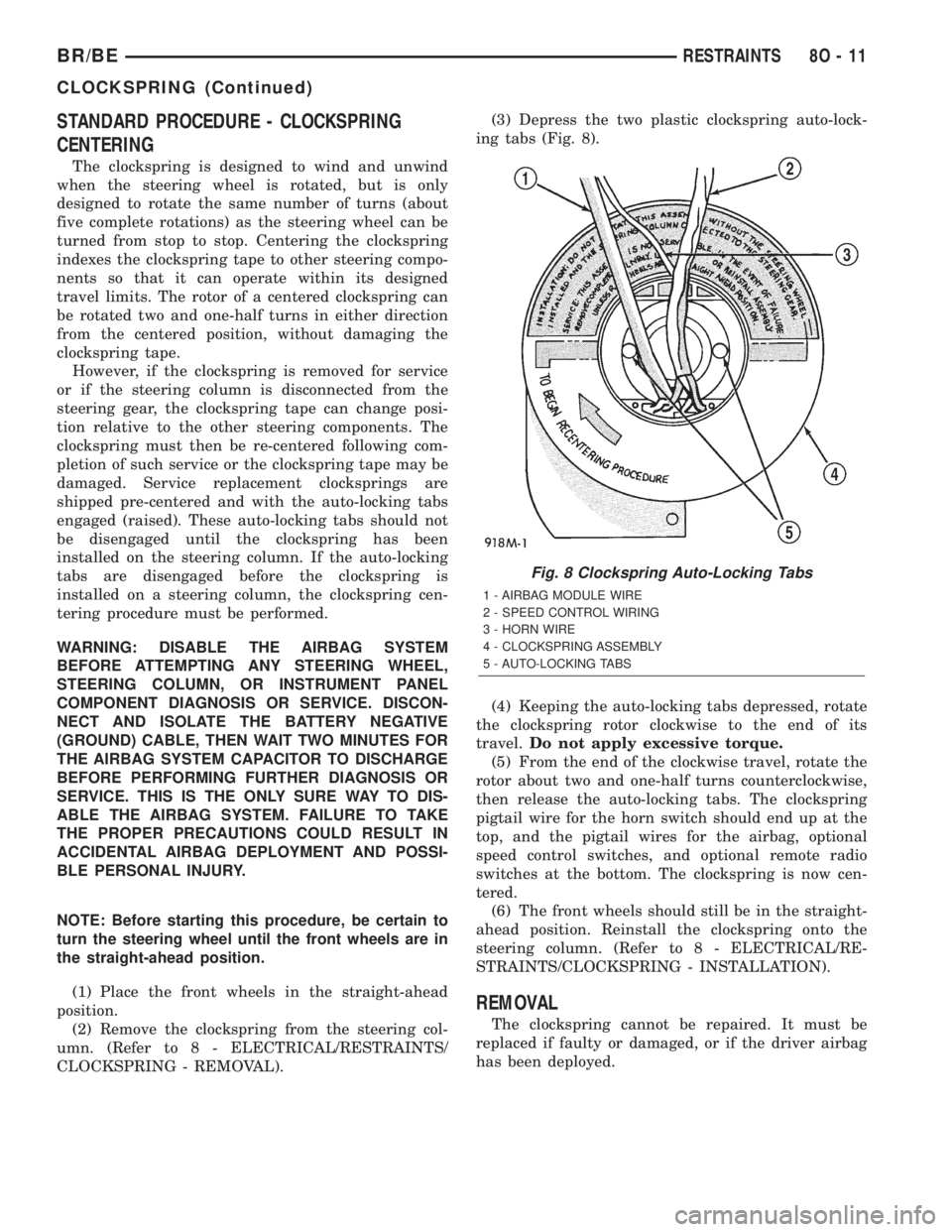
CLOCKSPRING - REMOVAL).(3) Depress the two plastic clockspring auto-lock-
ing tabs (Fig. 8).
(4) Keeping the auto-locking tabs depressed, rotate
the clockspring rotor clockwise to the end of its
travel.Do not apply excessive torque.
(5) From the end of the clockwise travel, rotate the
rotor about two and one-half turns counterclockwise,
then release the auto-locking tabs. The clockspring
pigtail wire for the horn switch should end up at the
top, and the pigtail wires for the airbag, optional
speed control switches, and optional remote radio
switches at the bottom. The clockspring is now cen-
tered.
(6) The front wheels should still be in the straight-
ahead position. Reinstall the clockspring onto the
steering column. (Refer to 8 - ELECTRICAL/RE-
STRAINTS/CLOCKSPRING - INSTALLATION).
REMOVAL
The clockspring cannot be repaired. It must be
replaced if faulty or damaged, or if the driver airbag
has been deployed.
Fig. 8 Clockspring Auto-Locking Tabs
1 - AIRBAG MODULE WIRE
2 - SPEED CONTROL WIRING
3 - HORN WIRE
4 - CLOCKSPRING ASSEMBLY
5 - AUTO-LOCKING TABS
BR/BERESTRAINTS 8O - 11
CLOCKSPRING (Continued)
Page 687 of 2889
WARNING: DISABLE THE AIRBAG SYSTEM
BEFORE ATTEMPTING ANY STEERING WHEEL,
STEERING COLUMN, OR INSTRUMENT PANEL
COMPONENT DIAGNOSIS OR SERVICE. DISCON-
NECT AND ISOLATE THE BATTERY NEGATIVE
(GROUND) CABLE, THEN WAIT TWO MINUTES FOR
THE AIRBAG SYSTEM CAPACITOR TO DISCHARGE
BEFORE PERFORMING FURTHER DIAGNOSIS OR
SERVICE. THIS IS THE ONLY SURE WAY TO DIS-
ABLE THE AIRBAG SYSTEM. FAILURE TO TAKE
THE PROPER PRECAUTIONS COULD RESULT IN
ACCIDENTAL AIRBAG DEPLOYMENT AND POSSI-
BLE PERSONAL INJURY.
NOTE: Before starting this procedure, be certain to
turn the steering wheel until the front wheels are in
the straight-ahead position.
(1) Place the front wheels in the straight-ahead
position.
(2) Remove the driver airbag from the steering
wheel. (Refer to 8 - ELECTRICAL/RESTRAINTS/
DRIVER AIRBAG - REMOVAL).
(3) If the vehicle is so equipped, disconnect the
clockspring pigtail wire connectors from the speed
control switches and the remote radio switches
located within the hub cavity of the steering wheel.
(4) Remove the nut that secures the steering wheel
armature to the steering column upper shaft, which
is located within the hub cavity of the steering wheel.
(5) Pull the steering wheel off of the steering col-
umn upper shaft spline using a steering wheel puller
(Special Tool C-3428-B).
(6) Remove the steering column opening cover
from the instrument panel. (Refer to 23 - BODY/IN-
STRUMENT PANEL/STEERING COLUMN OPEN-
ING COVER - REMOVAL).
(7) If the vehicle is so equipped, unscrew the lever
from the tilt steering column adjuster mechanism
located on the left side of the column just below the
multi-function switch control stalk. Turn the lever
counterclockwise to unscrew it from the adjuster.
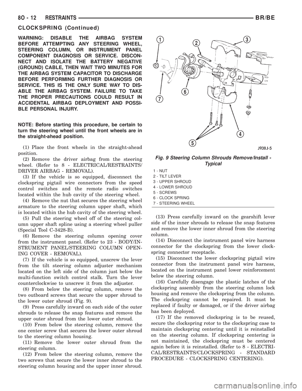
(8) From below the steering column, remove the
two outboard screws that secure the upper shroud to
the lower outer shroud (Fig. 9).
(9) Press carefully inward on each side of the outer
shrouds to release the snap features and remove the
upper outer shroud from the lower outer shroud.
(10) From below the steering column, remove the
one center screw that secures the lower outer shroud
to the steering column housing.
(11) Remove the lower outer shroud from the
steering column.
(12) From below the steering column, remove the
two screws that secure the lower inner shroud to the
steering column housing and the upper inner shroud.(13) Press carefully inward on the gearshift lever
side of the inner shrouds to release the snap features
and remove the lower inner shroud from the steering
column.
(14) Disconnect the instrument panel wire harness
connector for the clockspring from the lower clock-
spring connector receptacle.
(15) Disconnect the lower clockspring pigtail wire
connector from the instrument panel wire harness,
located on the instrument panel lower reinforcement
below the steering column.
(16) Carefully disengage the plastic latches of the
clockspring assembly from the steering column lock
housing and remove the clockspring from the column.
The clockspring cannot be repaired. It must be
replaced if faulty or damaged, or if the driver airbag
has been deployed.
(17) If the removed clockspring is to be reused,
secure the clockspring rotor to the clockspring case to
maintain clockspring centering until it is reinstalled
on the steering column. If clockspring centering is
not maintained, the clockspring must be centered
again before it is reinstalled. (Refer to 8 - ELECTRI-
CAL/RESTRAINTS/CLOCKSPRING - STANDARD
PROCEDURE - CLOCKSPRING CENTERING).
Fig. 9 Steering Column Shrouds Remove/Install -
Typical
1 - NUT
2 - TILT LEVER
3 - UPPER SHROUD
4 - LOWER SHROUD
5 - SCREWS
6 - CLOCK SPRING
7 - STEERING WHEEL
8O - 12 RESTRAINTSBR/BE
CLOCKSPRING (Continued)
Page 688 of 2889
INSTALLATION
The clockspring cannot be repaired. It must be
replaced if faulty or damaged, or if the driver airbag
has been deployed.
If the clockspring is not properly centered in rela-
tion to the steering wheel, steering shaft and steer-
ing gear, it may be damaged. (Refer to 8 -
ELECTRICAL/RESTRAINTS/CLOCKSPRING -
STANDARD PROCEDURE - CLOCKSPRING CEN-
TERING). Service replacement clocksprings are
shipped pre-centered and with a piece of tape cover-
ing the engaged clockspring auto-locking tabs. This
tape should not be removed until the clockspring has
been installed on the steering column. If the tape is
removed before the clockspring is installed on a
steering column, the clockspring centering procedure
must be performed.
WARNING: DISABLE THE AIRBAG SYSTEM
BEFORE ATTEMPTING ANY STEERING WHEEL,
STEERING COLUMN, OR INSTRUMENT PANEL
COMPONENT DIAGNOSIS OR SERVICE. DISCON-
NECT AND ISOLATE THE BATTERY NEGATIVE
(GROUND) CABLE, THEN WAIT TWO MINUTES FOR
THE AIRBAG SYSTEM CAPACITOR TO DISCHARGE
BEFORE PERFORMING FURTHER DIAGNOSIS OR
SERVICE. THIS IS THE ONLY SURE WAY TO DIS-
ABLE THE AIRBAG SYSTEM. FAILURE TO TAKE
THE PROPER PRECAUTIONS COULD RESULT IN
ACCIDENTAL AIRBAG DEPLOYMENT AND POSSI-
BLE PERSONAL INJURY.
NOTE: Before starting this procedure, be certain
that the front wheels are still in the straight-ahead
position.
(1) Carefully slide the centered clockspring down
over the steering column upper shaft until the clock-
spring latches engage the steering column lock hous-
ing (Fig. 9).
(2) Reconnect the lower clockspring pigtail wire
connector to the instrument panel wire harness con-
nector located near the instrument panel lower rein-
forcement, below the steering column. Be certain that
the pigtail wire locator clips are properly seated on
the outside of the wiring trough and that the connec-
tor latches are fully engaged.
(3) Reconnect the instrument panel wire harness
connector for the clockspring to the lower clockspring
connector receptacle.
(4) Position the lower inner shroud onto the steer-
ing column. Be certain to insert the gearshift lever
hider strip into the channel located on the inside sur-
face of the shroud.
(5) Align the locking tabs on the gearshift lever
side of the upper inner shroud with the receptacleson the lower inner shroud and apply hand pressure
to snap them together.
(6) From below the steering column, install and
tighten the two screws that secure the lower inner
shroud to the steering column housing and the upper
inner shroud. Tighten the screws to 2 N´m (18 in.
lbs.).
(7) Position the lower outer shroud onto the steer-
ing column. Be certain that the lower clockspring
pigtail wire is routed inside the shrouds.
(8) From below the steering column, install and
tighten the one center screw that secures the lower
outer shroud to the steering column housing. Tighten
the screw to 2 N´m (18 in. lbs.).
(9) Align the locking tabs on the upper outer
shroud with the receptacles on the lower outer
shroud and apply hand pressure to snap them
together.
(10) From below the steering column, install and
tighten the two outboard screws that secure the
lower outer shroud to the upper outer shroud.
Tighten the screws to 2 N´m (18 in. lbs.).
(11) If the vehicle is so equipped, reinstall the
lever into the tilt steering column adjuster on the left
side of the column. Turn the lever clockwise to screw
it into the adjuster.
(12) Reinstall the steering column opening cover
onto the instrument panel. (Refer to 23 - BODY/IN-
STRUMENT PANEL/STEERING COLUMN OPEN-
ING COVER - INSTALLATION).
(13) Reinstall the steering wheel onto the steering
column upper shaft. Be certain to index the flats on
the hub of the steering wheel with the formations on
the inside of the clockspring hub. Pull the upper
clockspring pigtail wires through the upper and
lower holes between the steering wheel back trim
cover and the steering wheel armature.
(14) Install and tighten the steering wheel mount-
ing nut. Tighten the nut to 61 N´m (45 ft. lbs.). Be
certain not to pinch the pigtail wires between the
steering wheel and the nut.
(15) If the vehicle is so equipped, reconnect the
upper clockspring pigtail wire connectors to the
speed control switches and/or the remote radio
switches. Be certain that the upper clockspring pig-
tail wires are routed between the steering wheel back
trim cover and the steering wheel armature.
(16) Reinstall the driver airbag onto the steering
wheel. (Refer to 8 - ELECTRICAL/RESTRAINTS/
DRIVER AIRBAG - INSTALLATION).
BR/BERESTRAINTS 8O - 13
CLOCKSPRING (Continued)
Page 689 of 2889
DRIVER AIRBAG
DESCRIPTION
The driver airbag protective trim cover is the most
visible part of the driver airbag. The airbag used in
this model is a Next Generation-type that complies
with revised federal airbag standards to deploy with
less force than those used in some prior models. The
driver airbag is located in the center of the steering
wheel, where it is secured with two screws to the
steering wheel armature. Concealed beneath the
driver airbag trim cover are the horn switch, the
folded airbag cushion, the airbag retainer or housing,
the airbag inflator, and the retainers that secure the
trim cover to the airbag housing. The resistive mem-
brane-type horn switch is secured with heat stakes to
the inside surface of the airbag trim cover, between
the trim cover and the folded airbag cushion. The air-
bag inflator is a conventional pyrotechnic-type unit
that is secured with nuts to four studs on the back of
the stamped metal airbag housing.
The driver airbag trim cover has locking blocks
molded into the back side of it that engage a lip
formed around the perimeter of the airbag housing.
Two stamped metal retainers then fit over the infla-
tor mounting studs on the back of the airbag housing
and tabs on the retainer are engaged in slots on the
inside of the trim cover, securely locking the cover
into place. One horn switch pigtail wire has an eyelet
terminal connector that is captured on the upper left
inflator mounting stud between the inflator and the
upper trim cover retainer. The connector insulator of
the other horn switch pigtail wire is routed between
the upper right inflator mounting stud and the infla-
tor, where it is captured by a small plastic that is
pushed onto the stud. The driver airbag cannot be
repaired, and must be replaced if deployed or in any
way damaged. The driver airbag trim cover and horn
switch are available as a unit, and may be disassem-
bled from the driver airbag for service replacement.
OPERATION
The driver airbag is deployed by an electrical sig-
nal generated by the Airbag Control Module (ACM)
through the driver airbag line 1 and line 2 (or squib)
circuits. When the ACM sends the proper electrical
signal to the airbag inflator, the electrical energy
generates enough heat to initiate a small pyrotechnic
charge which, in turn, ignites chemical pellets within
the inflator. Once ignited, these chemical pellets burn
rapidly and produce a large quantity of nitrogen gas.
The inflator is sealed to the back of the airbag hous-
ing and a diffuser in the inflator directs all of the
nitrogen gas into the airbag cushion, causing the
cushion to inflate. As the cushion inflates, the driver
airbag trim cover will split at predetermined break-out lines, then fold back out of the way along with
the horn switch. Following an airbag deployment, the
airbag cushion quickly deflates by venting the nitro-
gen gas towards the instrument panel through the
porous fabric material used on the steering wheel
side of the airbag cushion.
Some of the chemicals used to create the nitrogen
gas are considered hazardous in their solid state,
before they are burned, but they are securely sealed
within the airbag inflator. However, the nitrogen gas
that is produced when the chemicals are burned is
harmless. A small amount of residue from the burned
chemicals may cause some temporary discomfort if it
contacts the skin, eyes, or breathing passages. If skin
or eye irritation is noticed, rinse the affected area
with plenty of cool, clean water. If breathing pas-
sages are irritated, move to another area where there
is plenty of clean, fresh air to breath. If the irritation
is not alleviated by these actions, contact a physician.
REMOVAL
The following procedure is for replacement of a faulty
or damaged driver airbag. If the driver airbag has been
deployed, the clockspring and the steering column
assembly must also be replaced. (Refer to 8 - ELEC-
TRICAL/RESTRAINTS/CLOCKSPRING - REMOVAL)
(Refer to 19 - STEERING/COLUMN - REMOVAL).
WARNING: DISABLE THE AIRBAG SYSTEM BEFORE
ATTEMPTING ANY STEERING WHEEL, STEERING
COLUMN, OR INSTRUMENT PANEL COMPONENT
DIAGNOSIS OR SERVICE. DISCONNECT AND ISO-
LATE THE BATTERY NEGATIVE (GROUND) CABLE,
THEN WAIT TWO MINUTES FOR THE AIRBAG SYS-
TEM CAPACITOR TO DISCHARGE BEFORE PER-
FORMING FURTHER DIAGNOSIS OR SERVICE. THIS
IS THE ONLY SURE WAY TO DISABLE THE AIRBAG
SYSTEM. FAILURE TO TAKE THE PROPER PRECAU-
TIONS COULD RESULT IN ACCIDENTAL AIRBAG
DEPLOYMENT AND POSSIBLE PERSONAL INJURY.
WARNING: WHEN REMOVING A DEPLOYED AIR-
BAG, RUBBER GLOVES, EYE PROTECTION, AND A
LONG-SLEEVED SHIRT SHOULD BE WORN. THERE
MAY BE DEPOSITS ON THE AIRBAG CUSHION AND
OTHER INTERIOR SURFACES. IN LARGE DOSES,
THESE DEPOSITS MAY CAUSE IRRITATION TO THE
SKIN AND EYES.
(1) Disconnect and isolate the battery negative
cable. If either of the airbags has not been deployed,
wait two minutes for the system capacitor to dis-
charge before further service.
(2) From the underside of the steering wheel,
remove the two screws that secure the driver airbag
to the steering wheel armature (Fig. 10).
8O - 14 RESTRAINTSBR/BE
Page 690 of 2889
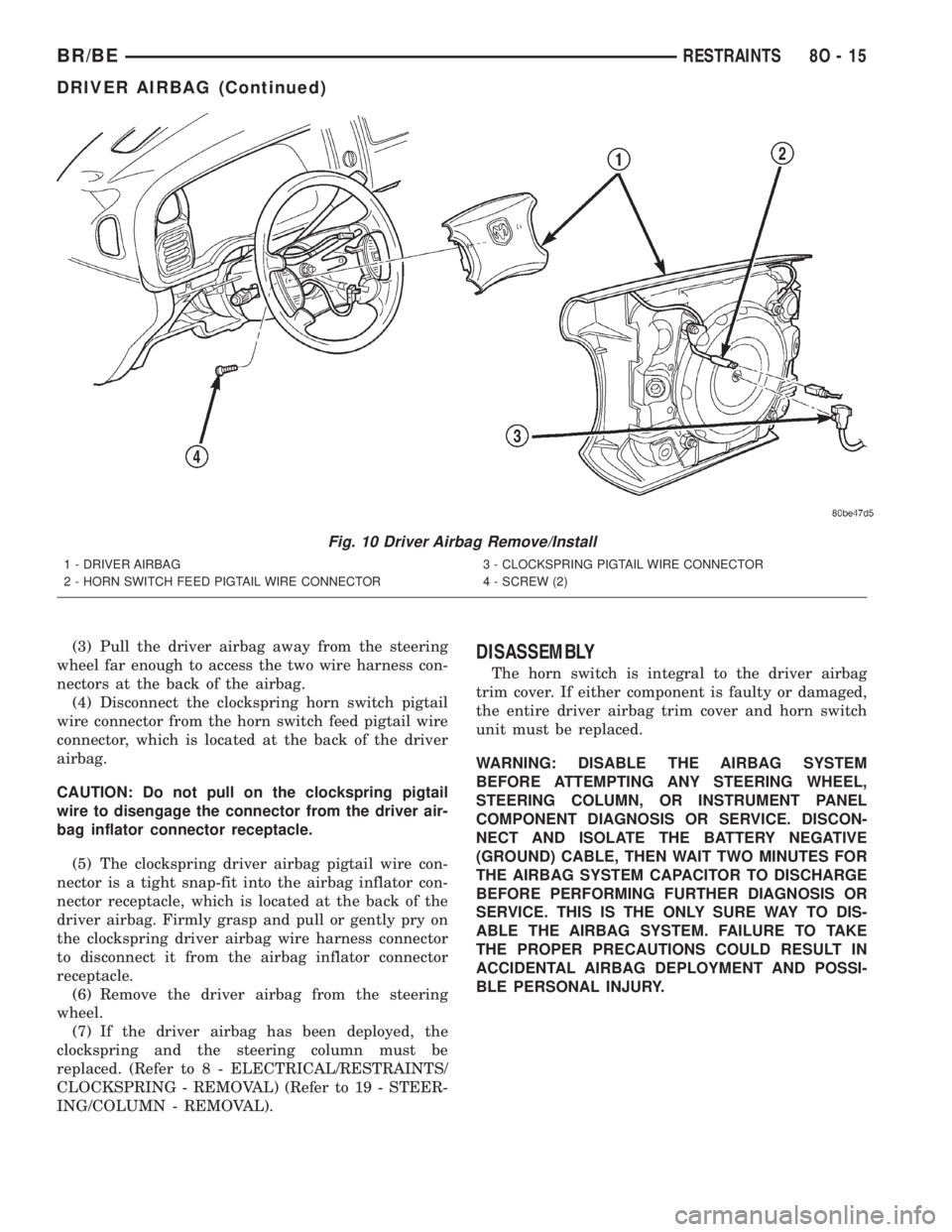
(3) Pull the driver airbag away from the steering
wheel far enough to access the two wire harness con-
nectors at the back of the airbag.
(4) Disconnect the clockspring horn switch pigtail
wire connector from the horn switch feed pigtail wire
connector, which is located at the back of the driver
airbag.
CAUTION: Do not pull on the clockspring pigtail
wire to disengage the connector from the driver air-
bag inflator connector receptacle.
(5) The clockspring driver airbag pigtail wire con-
nector is a tight snap-fit into the airbag inflator con-
nector receptacle, which is located at the back of the
driver airbag. Firmly grasp and pull or gently pry on
the clockspring driver airbag wire harness connector
to disconnect it from the airbag inflator connector
receptacle.
(6) Remove the driver airbag from the steering
wheel.
(7) If the driver airbag has been deployed, the
clockspring and the steering column must be
replaced. (Refer to 8 - ELECTRICAL/RESTRAINTS/
CLOCKSPRING - REMOVAL) (Refer to 19 - STEER-
ING/COLUMN - REMOVAL).DISASSEMBLY
The horn switch is integral to the driver airbag
trim cover. If either component is faulty or damaged,
the entire driver airbag trim cover and horn switch
unit must be replaced.
WARNING: DISABLE THE AIRBAG SYSTEM
BEFORE ATTEMPTING ANY STEERING WHEEL,
STEERING COLUMN, OR INSTRUMENT PANEL
COMPONENT DIAGNOSIS OR SERVICE. DISCON-
NECT AND ISOLATE THE BATTERY NEGATIVE
(GROUND) CABLE, THEN WAIT TWO MINUTES FOR
THE AIRBAG SYSTEM CAPACITOR TO DISCHARGE
BEFORE PERFORMING FURTHER DIAGNOSIS OR
SERVICE. THIS IS THE ONLY SURE WAY TO DIS-
ABLE THE AIRBAG SYSTEM. FAILURE TO TAKE
THE PROPER PRECAUTIONS COULD RESULT IN
ACCIDENTAL AIRBAG DEPLOYMENT AND POSSI-
BLE PERSONAL INJURY.
Fig. 10 Driver Airbag Remove/Install
1 - DRIVER AIRBAG
2 - HORN SWITCH FEED PIGTAIL WIRE CONNECTOR3 - CLOCKSPRING PIGTAIL WIRE CONNECTOR
4 - SCREW (2)
BR/BERESTRAINTS 8O - 15
DRIVER AIRBAG (Continued)