water pump DODGE RAM 2001 Service Manual Online
[x] Cancel search | Manufacturer: DODGE, Model Year: 2001, Model line: RAM, Model: DODGE RAM 2001Pages: 2889, PDF Size: 68.07 MB
Page 1373 of 2889
(10) Loosen oil pan bolts and remove the front oil
pan bolts that mount the pan to the timing chain
cover.
(11) Remove the cover bolts.
(12) Remove timing chain cover and gasket using
extreme caution to avoid damaging oil pan gasket.
(13) Inspect surface of cover. Remove any burrs or
high spots.
INSTALLATION
(1) Be sure mating surfaces of timing chain cover
and cylinder block are clean and free from burrs.
(2) Lubricate the pump rotors using petroleum
jelly or lubriplate (Refer to 9 - ENGINE/LUBRICA-
TION/OIL PUMP - INSTALLATION).
(3) Using a new cover gasket, carefully install tim-
ing chain cover to avoid damaging oil pan gasket.
Use a small amount of MopartSilicone Rubber Adhe-
sive Sealant, or equivalent, at the joint between tim-
ing chain cover gasket and the oil pan gasket. Finger
tighten the timing chain cover bolts at this time.
(4) Tighten timing chain cover bolts to 47 N´m (35
ft. lbs.) torque. Tighten oil pan bolts to 24 N´m (215
in. lbs.) torque.
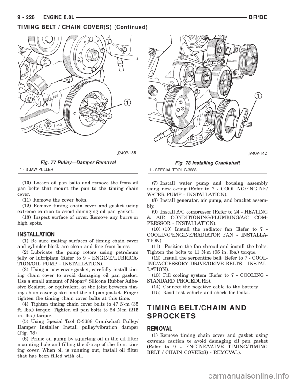
(5) Using Special Tool C-3688 Crankshaft Pulley/
Damper Installer Install pulley/vibration damper
(Fig. 78)
(6) Prime oil pump by squirting oil in the oil filter
mounting hole and filling the J-trap of the front tim-
ing cover. When oil is running out, install oil filter
that has been filled with oil.(7) Install water pump and housing assembly
using new o-ring (Refer to 7 - COOLING/ENGINE/
WATER PUMP - INSTALLATION).
(8) Install generator, air pump, and bracket assem-
bly.
(9) Install A/C compressor (Refer to 24 - HEATING
& AIR CONDITIONING/PLUMBING/A/C COM-
PRESSOR - INSTALLATION).
(10) (10) Install the radiator fan (Refer to 7 -
COOLING/ENGINE/RADIATOR FAN - INSTALLA-
TION).
(11) Position the fan shroud and install the bolts.
Tighten the bolts to 11 N´m (95 in. lbs.) torque.
(12) Install the serpentine belt (Refer to 7 - COOL-
ING/ACCESSORY DRIVE/DRIVE BELTS - INSTAL-
LATION).
(13) Fill cooling system (Refer to 7 - COOLING -
STANDARD PROCEDURE).
(14) Connect the negative cable to the battery.
(15) Road test vehicle and check for leaks.
TIMING BELT/CHAIN AND
SPROCKETS
REMOVAL
(1) Remove timing chain cover and gasket using
extreme caution to avoid damaging oil pan gasket
(Refer to 9 - ENGINE/VALVE TIMING/TIMING
BELT / CHAIN COVER(S) - REMOVAL).
Fig. 77 PulleyÐDamper Removal
1-3JAWPULLER
Fig. 78 Installing Crankshaft
1 - SPECIAL TOOL C-3688
9 - 226 ENGINE 8.0LBR/BE
TIMING BELT / CHAIN COVER(S) (Continued)
Page 1380 of 2889
CONDITION POSSIBLE CAUSES CORRECTION
4. Oil cooler leak 4. Check and replace the oil cooler.
5. High blow-by forcing oil out the
breather.5. Check the breather tube area for signs of
oil loss. Perform the required repairs.
6. Turbocharger leaking oil to the air
intake.6. Inspect the air ducts for evidence of oil
transfer. Repair as required.
7. Piston rings not sealing (oil being
consumed by the engine).7. Perform blow-by check. Repair as
required.
COMPRESSION KNOCKS 1. Air in the fuel system. 1. Bleed the fuel system (Refer to 14 -
FUEL SYSTEM/FUEL DELIVERY -
STANDARD PROCEDURE).
2. Poor quality fuel or water/gasoline
contaminated fuel.2. Verify by operating from a temporary
tank with good fuel. Clean and flush the
fuel tank. Replace fuel/water separator filter.
3. Engine overloaded. 3. Verify the engine load rating is not being
exceeded.
4. Incorrect injection pump timing. 4. Check injection pump for proper
installation.
5. Improperly operating injectors. 5. Check and replace inoperative injectors.
EXCESSIVE VIBRATION 1. Loose or broken engine mounts. 1. Replace engine mounts.
2. Damaged fan or improperly
operating accessories.2. Check and replace the vibrating
components.
3. Improperly operating vibration
damper3. Inspect/replace vibration damper.
4. Improperly operating viscous fan
drive.4. Inspect/replace fan drive.
5. Worn or damaged generator
bearing.5. Check/replace generator.
6. Flywheel housing misaligned. 6. Check/correct flywheel alignment.
7. Loose or broken power
component.7. Inspect the crankshaft and rods for
damage that causes an unbalance
condition. Repair/replace as required.
8. Worn or unbalanced driveline
components.8. Check/repair driveline components.
EXCESSIVE ENGINE
NOISES1. Drive belt squeal, insufficient
tension or abnormally high loading.1. Check the automatic tensioner and
inspect the drive belt. Make sure water
pump, tensioner pulley, fan hub and
generator turn freely.
2. Intake air or exhaust leaks. 2. Refer to Excessive Exhaust Smoke
(Refer to 9 - ENGINE - DIAGNOSIS AND
TESTING).
3. Excessive valve lash. 3. Adjust valves. Make sure the push rods
are not bent and rocker arms, adjusting
screws, crossheads, are not severely worn.
Replace bent or severely worn components.
BR/BEENGINE 5.9L DIESEL 9 - 233
ENGINE 5.9L DIESEL (Continued)
Page 1395 of 2889
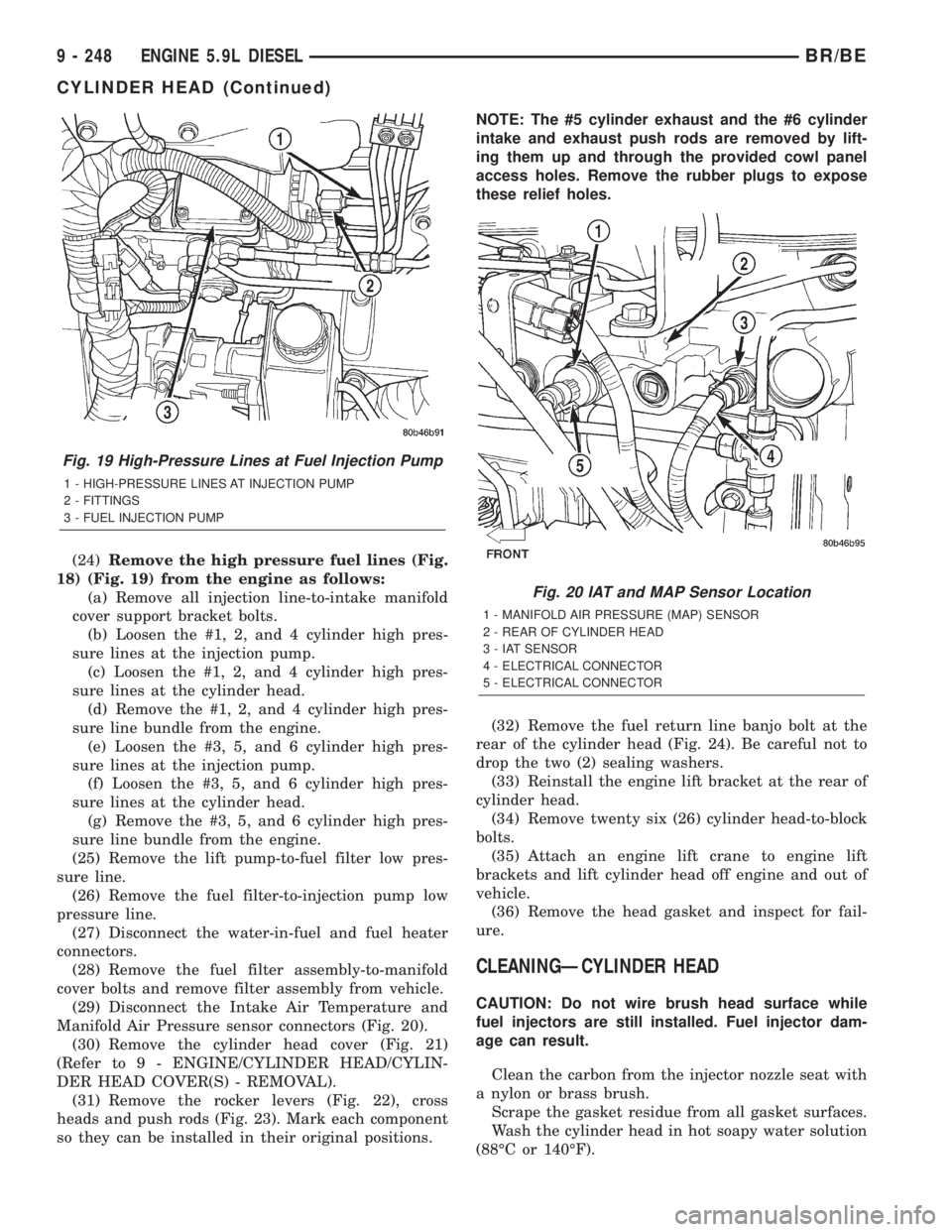
(24)Remove the high pressure fuel lines (Fig.
18) (Fig. 19) from the engine as follows:
(a) Remove all injection line-to-intake manifold
cover support bracket bolts.
(b) Loosen the #1, 2, and 4 cylinder high pres-
sure lines at the injection pump.
(c) Loosen the #1, 2, and 4 cylinder high pres-
sure lines at the cylinder head.
(d) Remove the #1, 2, and 4 cylinder high pres-
sure line bundle from the engine.
(e) Loosen the #3, 5, and 6 cylinder high pres-
sure lines at the injection pump.
(f) Loosen the #3, 5, and 6 cylinder high pres-
sure lines at the cylinder head.
(g) Remove the #3, 5, and 6 cylinder high pres-
sure line bundle from the engine.
(25) Remove the lift pump-to-fuel filter low pres-
sure line.
(26) Remove the fuel filter-to-injection pump low
pressure line.
(27) Disconnect the water-in-fuel and fuel heater
connectors.
(28) Remove the fuel filter assembly-to-manifold
cover bolts and remove filter assembly from vehicle.
(29) Disconnect the Intake Air Temperature and
Manifold Air Pressure sensor connectors (Fig. 20).
(30) Remove the cylinder head cover (Fig. 21)
(Refer to 9 - ENGINE/CYLINDER HEAD/CYLIN-
DER HEAD COVER(S) - REMOVAL).
(31) Remove the rocker levers (Fig. 22), cross
heads and push rods (Fig. 23). Mark each component
so they can be installed in their original positions.NOTE: The #5 cylinder exhaust and the #6 cylinder
intake and exhaust push rods are removed by lift-
ing them up and through the provided cowl panel
access holes. Remove the rubber plugs to expose
these relief holes.
(32) Remove the fuel return line banjo bolt at the
rear of the cylinder head (Fig. 24). Be careful not to
drop the two (2) sealing washers.
(33) Reinstall the engine lift bracket at the rear of
cylinder head.
(34) Remove twenty six (26) cylinder head-to-block
bolts.
(35) Attach an engine lift crane to engine lift
brackets and lift cylinder head off engine and out of
vehicle.
(36) Remove the head gasket and inspect for fail-
ure.
CLEANINGÐCYLINDER HEAD
CAUTION: Do not wire brush head surface while
fuel injectors are still installed. Fuel injector dam-
age can result.
Clean the carbon from the injector nozzle seat with
a nylon or brass brush.
Scrape the gasket residue from all gasket surfaces.
Wash the cylinder head in hot soapy water solution
(88ÉC or 140ÉF).
Fig. 19 High-Pressure Lines at Fuel Injection Pump
1 - HIGH-PRESSURE LINES AT INJECTION PUMP
2 - FITTINGS
3 - FUEL INJECTION PUMP
Fig. 20 IAT and MAP Sensor Location
1 - MANIFOLD AIR PRESSURE (MAP) SENSOR
2 - REAR OF CYLINDER HEAD
3 - IAT SENSOR
4 - ELECTRICAL CONNECTOR
5 - ELECTRICAL CONNECTOR
9 - 248 ENGINE 5.9L DIESELBR/BE
CYLINDER HEAD (Continued)
Page 1398 of 2889
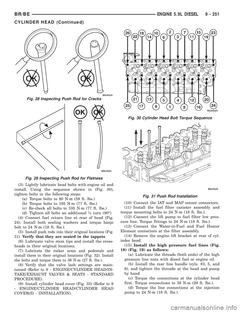
(3) Lightly lubricate head bolts with engine oil and
install. Using the sequence shown in (Fig. 30),
tighten bolts in the following steps:
(a) Torque bolts to 80 N´m (59 ft. lbs.)
(b) Torque bolts to 105 N´m (77 ft. lbs.)
(c) Re-check all bolts to 105 N´m (77 ft. lbs.)
(d) Tighten all bolts an additional ò turn (90É)
(4) Connect fuel return line at rear of head (Fig.
24). Install both sealing washers and torque banjo
bolt to 24 N´m (18 ft. lbs.).
(5)
Install push rods into their original locations (Fig.
31).Verify that they are seated in the tappets
.
(6) Lubricate valve stem tips and install the cross-
heads in their original locations.
(7)
Lubricate the rocker arms and pedestals and
install them in their original locations (Fig. 32). Install
the bolts and torque them to 36 N´m (27 ft. lbs.).
(8) Verify that the valve lash settings are main-
tained (Refer to 9 - ENGINE/CYLINDER HEAD/IN-
TAKE/EXHAUST VALVES & SEATS - STANDARD
PROCEDURE).
(9) Install cylinder head cover (Fig. 33) (Refer to 9
- ENGINE/CYLINDER HEAD/CYLINDER HEAD
COVER(S) - INSTALLATION).(10) Connect the IAT and MAP sensor connectors.
(11) Install the fuel filter canister assembly and
torque mounting bolts to 24 N´m (18 ft. lbs.).
(12) Connect the lift pump to fuel filter low pres-
sure line. Torque fittings to 24 N´m (18 ft. lbs.).
(13) Connect the Water-in-Fuel and Fuel Heater
Element connectors at the filter assembly.
(14) Remove the engine lift bracket at rear of cyl-
inder head.
(15)Install the high pressure fuel lines (Fig.
18) (Fig. 19) as follows:
(a) Lubricate the threads (both ends) of the high
pressure line nuts with diesel fuel or engine oil.
(b) Install the rear line bundle (cyls. #3, 5, and
6), and tighten the threads at the head and pump
by hand.
(c) Torque the connections at the cylinder head
first. Torque connections to 38 N´m (28 ft. lbs.).
(d) Torque the line connections at the injection
pump to 24 N´m (18 ft. lbs.).
Fig. 28 Inspecting Push Rod for Cracks
Fig. 29 Inspecting Push Rod for Flatness
Fig. 30 Cylinder Head Bolt Torque Sequence
Fig. 31 Push Rod Installation
BR/BEENGINE 5.9L DIESEL 9 - 251
CYLINDER HEAD (Continued)
Page 1541 of 2889
FUEL DELIVERY - DIESEL
TABLE OF CONTENTS
page page
FUEL DELIVERY - DIESEL
DESCRIPTION...........................54
OPERATION.............................56
DIAGNOSIS AND TESTING.................56
AIR IN FUEL SYSTEM...................56
FUEL SUPPLY RESTRICTIONS............56
STANDARD PROCEDURE..................56
WATER DRAINING AT FUEL FILTER........56
CLEANING FUEL SYSTEM PARTS..........57
AIR BLEED............................57
SPECIFICATIONS........................58
SPECIAL TOOLS.........................59
FUEL FILTER / WATER SEPARATOR
DESCRIPTION...........................59
OPERATION.............................59
REMOVAL..............................60
INSTALLATION...........................61
FUEL HEATER
DESCRIPTION...........................62
OPERATION.............................62
DIAGNOSIS AND TESTING.................62
FUEL HEATER.........................62
REMOVAL..............................63
FUEL HEATER RELAY
DESCRIPTION...........................63
OPERATION.............................63
DIAGNOSIS AND TESTING.................64
FUEL HEATER RELAY...................64
REMOVAL..............................65
INSTALLATION...........................65
FUEL INJECTION PUMP
DESCRIPTION...........................65
OPERATION.............................66
DIAGNOSIS AND TESTING.................66
FUEL INJECTION PUMP TIMING...........66
REMOVAL..............................68
INSTALLATION...........................71
FUEL INJECTION PUMP DATA PLATE
SPECIFICATIONS........................73FUEL LEVEL SENDING UNIT / SENSOR
DESCRIPTION...........................73
OPERATION.............................73
FUEL LINES
DESCRIPTION...........................73
OPERATION.............................74
DIAGNOSIS AND TESTING.................74
HIGH-PRESSURE FUEL LINE LEAK.........74
REMOVAL..............................75
INSTALLATION...........................77
FUEL TANK
DESCRIPTION...........................78
FUEL TANK MODULE
DESCRIPTION...........................78
OPERATION.............................78
REMOVAL..............................78
INSTALLATION...........................79
FUEL TRANSFER PUMP
DESCRIPTION...........................79
OPERATION.............................79
DIAGNOSIS AND TESTING.................80
FUEL TRANSFER PUMP PRESSURE........80
REMOVAL..............................83
INSTALLATION...........................83
OVERFLOW VALVE
DESCRIPTION...........................83
OPERATION.............................83
DIAGNOSIS AND TESTING.................84
OVERFLOW VALVE.....................84
REMOVAL..............................84
INSTALLATION...........................85
WATER IN FUEL SENSOR
DESCRIPTION...........................85
OPERATION.............................85
REMOVAL..............................85
FUEL DRAIN MANIFOLD
DESCRIPTION...........................86
OPERATION.............................86
REMOVAL..............................86
INSTALLATION...........................86
FUEL DELIVERY - DIESEL
DESCRIPTION - DIESEL FUEL DELIVERY
SYSTEM
The fuel system on the Cummins 24 valveÐTurbo
Diesel Engine uses anelectronicfuel injection
pump with three control modules.Also refer to the Powertrain Control Module (PCM)
or Engine Control Module sections.
Some fuel system components are shown in (Fig.
1).
The fuel delivery system consists of the:
²Accelerator pedal
²Air cleaner housing/element
²Fuel drain manifold (passage)
14 - 54 FUEL DELIVERY - DIESELBR/BE
Page 1542 of 2889
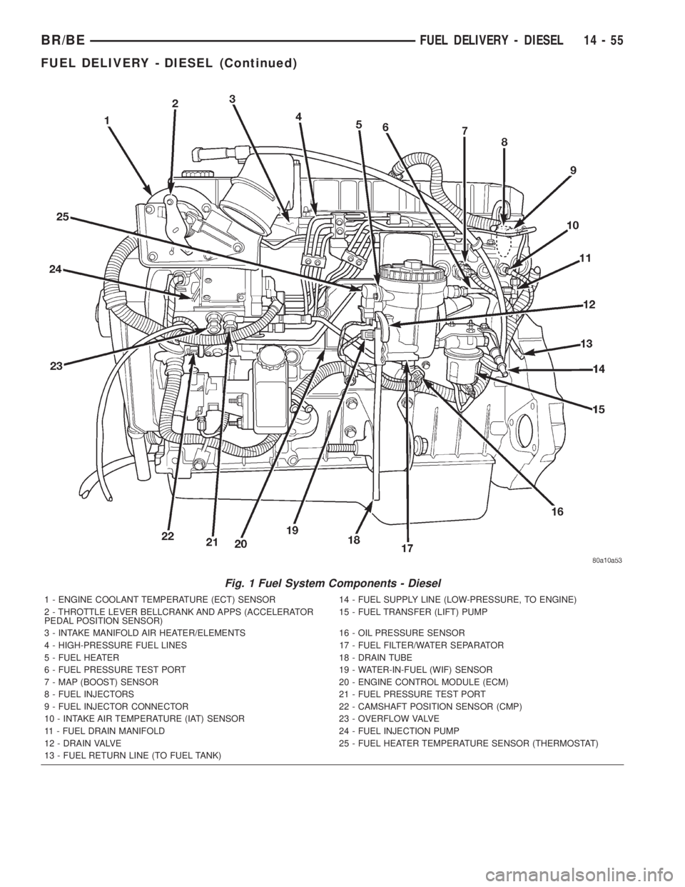
Fig. 1 Fuel System Components - Diesel
1 - ENGINE COOLANT TEMPERATURE (ECT) SENSOR 14 - FUEL SUPPLY LINE (LOW-PRESSURE, TO ENGINE)
2 - THROTTLE LEVER BELLCRANK AND APPS (ACCELERATOR
PEDAL POSITION SENSOR)15 - FUEL TRANSFER (LIFT) PUMP
3 - INTAKE MANIFOLD AIR HEATER/ELEMENTS 16 - OIL PRESSURE SENSOR
4 - HIGH-PRESSURE FUEL LINES 17 - FUEL FILTER/WATER SEPARATOR
5 - FUEL HEATER 18 - DRAIN TUBE
6 - FUEL PRESSURE TEST PORT 19 - WATER-IN-FUEL (WIF) SENSOR
7 - MAP (BOOST) SENSOR 20 - ENGINE CONTROL MODULE (ECM)
8 - FUEL INJECTORS 21 - FUEL PRESSURE TEST PORT
9 - FUEL INJECTOR CONNECTOR 22 - CAMSHAFT POSITION SENSOR (CMP)
10 - INTAKE AIR TEMPERATURE (IAT) SENSOR 23 - OVERFLOW VALVE
11 - FUEL DRAIN MANIFOLD 24 - FUEL INJECTION PUMP
12 - DRAIN VALVE 25 - FUEL HEATER TEMPERATURE SENSOR (THERMOSTAT)
13 - FUEL RETURN LINE (TO FUEL TANK)
BR/BEFUEL DELIVERY - DIESEL 14 - 55
FUEL DELIVERY - DIESEL (Continued)
Page 1543 of 2889
²Fuel filter/water separator
²Fuel heater
²Fuel heater relay
²Fuel transfer (lift) pump
²Fuel injection pump
²Fuel injectors
²Fuel heater temperature sensor
²Fuel tank
²Fuel tank filler/vent tube assembly
²Fuel tank filler tube cap
²Fuel tank module containing the rollover valve,
fuel gauge sending unit (fuel level sensor) and a sep-
arate fuel filter located at bottom of tank module
²Fuel tubes/lines/hoses
²High-pressure fuel injector lines
²In-tank fuel filter (at bottom of fuel tank mod-
ule)
²Low-pressure fuel supply lines
²Low-pressure fuel return line
²Overflow valve
²Quick-connect fittings
²Throttle cable
²Water draining
OPERATION
WARNING: HIGH-PRESSURE FUEL LINES DELIVER
DIESEL FUEL UNDER EXTREME PRESSURE FROM
THE INJECTION PUMP TO THE FUEL INJECTORS.
THIS MAY BE AS HIGH AS 120,000 KPA (17,405
PSI). USE EXTREME CAUTION WHEN INSPECTING
FOR HIGH-PRESSURE FUEL LEAKS. INSPECT FOR
HIGH-PRESSURE FUEL LEAKS WITH A SHEET OF
CARDBOARD. HIGH FUEL INJECTION PRESSURE
CAN CAUSE PERSONAL INJURY IF CONTACT IS
MADE WITH THE SKIN.
DIAGNOSIS AND TESTING - AIR IN FUEL
SYSTEM
Air will enter the fuel system whenever fuel supply
lines, separator filters, injection pump, high-pressure
lines or injectors are removed or disconnected. Air
trapped in the fuel system can result in hard start-
ing, a rough running engine, engine misfire, low
power, excessive smoke and fuel knock. After service
is performed, air must be bled from the system
before starting the engine.Inspect the fuel system from the fuel transfer
pump to the injectors for loose connections. Leaking
fuel is an indicator of loose connections or defective
seals. Air can also enter the fuel system between the
fuel tank and the transfer pump. Inspect the fuel
tank and fuel lines for damage that might allow air
into the system.
For air bleeding, refer to the Air Bleed Procedure.
DIAGNOSIS AND TESTING - FUEL SUPPLY
RESTRICTIONS
LOW-PRESSURE LINES
Fuel supply line restrictions or a defective fuel
transfer pump can cause starting problems and pre-
vent engine from accelerating. The starting problems
include; low power and/or white fog like exhaust.
Test all fuel supply lines for restrictions or block-
age. Flush or replace as necessary. Bleed fuel system
of air once a fuel supply line has been replaced. Refer
to Air Bleed Procedure for procedures.
To test for fuel line restrictions, a vacuum restric-
tion test may be performed. Refer to Fuel Transfer
Pump Pressure Test.
HIGH-PRESSURE LINES
Restricted (kinked or bent) high-pressure lines can
cause starting problems, poor engine performance,
engine mis-fire and white smoke from exhaust.
Examine all high-pressure lines for any damage.
Each radius on each high-pressure line must be
smooth and free of any bends or kinks.
Replace damaged, restricted or leaking high-pres-
sure fuel lines with correct replacement line.
CAUTION: All high-pressure fuel lines must be
clamped securely in place in holders. Lines cannot
contact each other or other components. Do not
attempt to weld high-pressure fuel lines or to repair
lines that are damaged. If line is kinked or bent, it
must be replaced. Use only recommended lines
when replacement of high-pressure fuel line is nec-
essary.
STANDARD PROCEDURES - WATER DRAINING
AT FUEL FILTER
Refer to Fuel Filter/Water Separator removal/in-
stallation for procedures.
14 - 56 FUEL DELIVERY - DIESELBR/BE
FUEL DELIVERY - DIESEL (Continued)
Page 1546 of 2889
SPECIAL TOOLS
DIESEL FUEL SYSTEMFUEL FILTER / WATER
SEPARATOR
DESCRIPTION
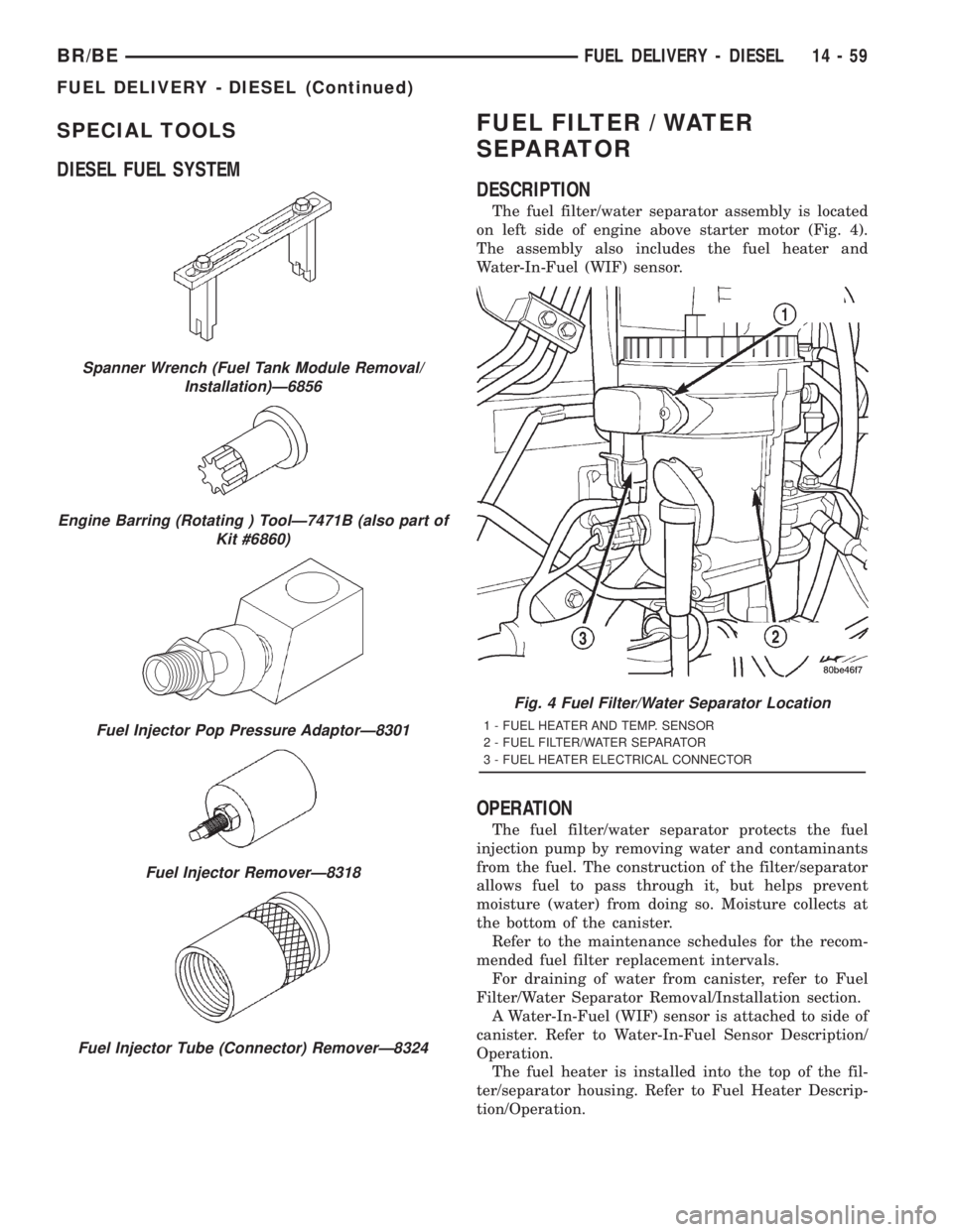
The fuel filter/water separator assembly is located
on left side of engine above starter motor (Fig. 4).
The assembly also includes the fuel heater and
Water-In-Fuel (WIF) sensor.
OPERATION
The fuel filter/water separator protects the fuel
injection pump by removing water and contaminants
from the fuel. The construction of the filter/separator
allows fuel to pass through it, but helps prevent
moisture (water) from doing so. Moisture collects at
the bottom of the canister.
Refer to the maintenance schedules for the recom-
mended fuel filter replacement intervals.
For draining of water from canister, refer to Fuel
Filter/Water Separator Removal/Installation section.
A Water-In-Fuel (WIF) sensor is attached to side of
canister. Refer to Water-In-Fuel Sensor Description/
Operation.
The fuel heater is installed into the top of the fil-
ter/separator housing. Refer to Fuel Heater Descrip-
tion/Operation.
Spanner Wrench (Fuel Tank Module Removal/
Installation)Ð6856
Engine Barring (Rotating ) ToolÐ7471B (also part of
Kit #6860)
Fuel Injector Pop Pressure AdaptorÐ8301
Fuel Injector RemoverÐ8318
Fuel Injector Tube (Connector) RemoverÐ8324
Fig. 4 Fuel Filter/Water Separator Location
1 - FUEL HEATER AND TEMP. SENSOR
2 - FUEL FILTER/WATER SEPARATOR
3 - FUEL HEATER ELECTRICAL CONNECTOR
BR/BEFUEL DELIVERY - DIESEL 14 - 59
FUEL DELIVERY - DIESEL (Continued)
Page 1566 of 2889
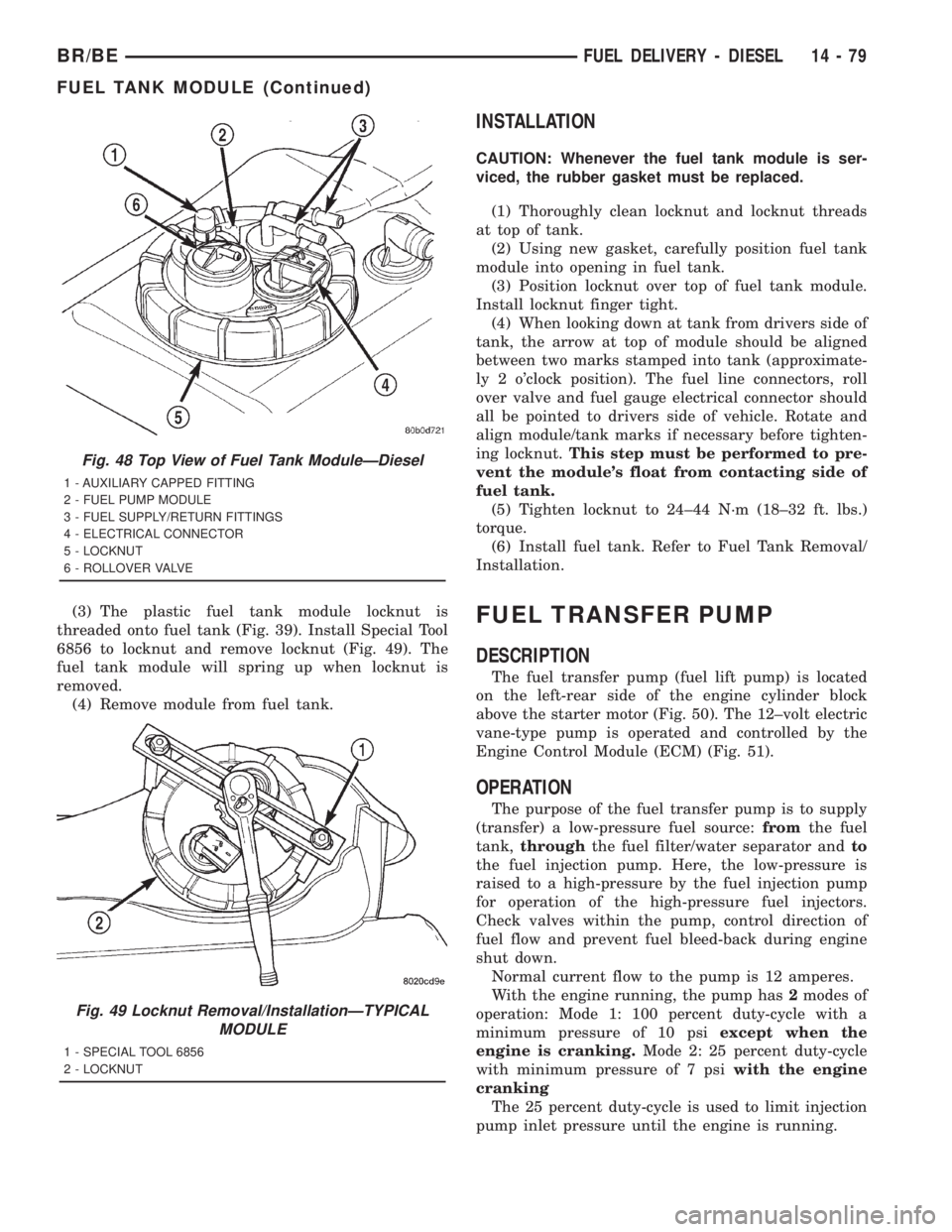
(3) The plastic fuel tank module locknut is
threaded onto fuel tank (Fig. 39). Install Special Tool
6856 to locknut and remove locknut (Fig. 49). The
fuel tank module will spring up when locknut is
removed.
(4) Remove module from fuel tank.
INSTALLATION
CAUTION: Whenever the fuel tank module is ser-
viced, the rubber gasket must be replaced.
(1) Thoroughly clean locknut and locknut threads
at top of tank.
(2) Using new gasket, carefully position fuel tank
module into opening in fuel tank.
(3) Position locknut over top of fuel tank module.
Install locknut finger tight.
(4) When looking down at tank from drivers side of
tank, the arrow at top of module should be aligned
between two marks stamped into tank (approximate-
ly 2 o'clock position). The fuel line connectors, roll
over valve and fuel gauge electrical connector should
all be pointed to drivers side of vehicle. Rotate and
align module/tank marks if necessary before tighten-
ing locknut.This step must be performed to pre-
vent the module's float from contacting side of
fuel tank.
(5) Tighten locknut to 24±44 N´m (18±32 ft. lbs.)
torque.
(6) Install fuel tank. Refer to Fuel Tank Removal/
Installation.
FUEL TRANSFER PUMP
DESCRIPTION
The fuel transfer pump (fuel lift pump) is located
on the left-rear side of the engine cylinder block
above the starter motor (Fig. 50). The 12±volt electric
vane-type pump is operated and controlled by the
Engine Control Module (ECM) (Fig. 51).
OPERATION
The purpose of the fuel transfer pump is to supply
(transfer) a low-pressure fuel source:fromthe fuel
tank,throughthe fuel filter/water separator andto
the fuel injection pump. Here, the low-pressure is
raised to a high-pressure by the fuel injection pump
for operation of the high-pressure fuel injectors.
Check valves within the pump, control direction of
fuel flow and prevent fuel bleed-back during engine
shut down.
Normal current flow to the pump is 12 amperes.
With the engine running, the pump has2modes of
operation: Mode 1: 100 percent duty-cycle with a
minimum pressure of 10 psiexcept when the
engine is cranking.Mode 2: 25 percent duty-cycle
with minimum pressure of 7 psiwith the engine
cranking
The 25 percent duty-cycle is used to limit injection
pump inlet pressure until the engine is running.
Fig. 48 Top View of Fuel Tank ModuleÐDiesel
1 - AUXILIARY CAPPED FITTING
2 - FUEL PUMP MODULE
3 - FUEL SUPPLY/RETURN FITTINGS
4 - ELECTRICAL CONNECTOR
5 - LOCKNUT
6 - ROLLOVER VALVE
Fig. 49 Locknut Removal/InstallationÐTYPICAL
MODULE
1 - SPECIAL TOOL 6856
2 - LOCKNUT
BR/BEFUEL DELIVERY - DIESEL 14 - 79
FUEL TANK MODULE (Continued)
Page 1568 of 2889
Refer to Fuel Transfer Pump Description/Operation
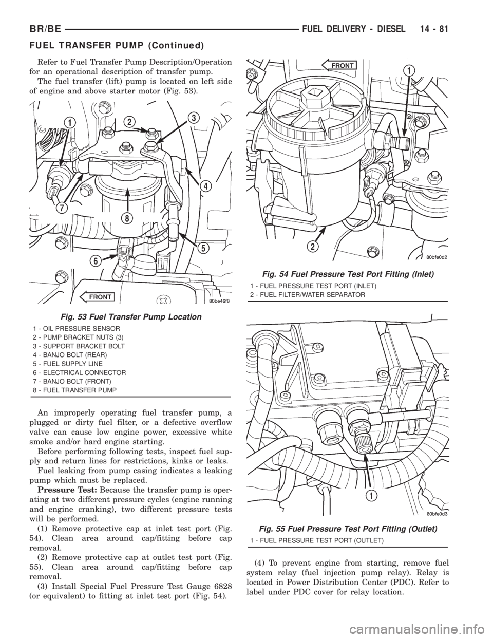
for an operational description of transfer pump.
The fuel transfer (lift) pump is located on left side
of engine and above starter motor (Fig. 53).
An improperly operating fuel transfer pump, a
plugged or dirty fuel filter, or a defective overflow
valve can cause low engine power, excessive white
smoke and/or hard engine starting.
Before performing following tests, inspect fuel sup-
ply and return lines for restrictions, kinks or leaks.
Fuel leaking from pump casing indicates a leaking
pump which must be replaced.
Pressure Test:Because the transfer pump is oper-
ating at two different pressure cycles (engine running
and engine cranking), two different pressure tests
will be performed.
(1) Remove protective cap at inlet test port (Fig.
54). Clean area around cap/fitting before cap
removal.
(2) Remove protective cap at outlet test port (Fig.
55). Clean area around cap/fitting before cap
removal.
(3) Install Special Fuel Pressure Test Gauge 6828
(or equivalent) to fitting at inlet test port (Fig. 54).(4) To prevent engine from starting, remove fuel
system relay (fuel injection pump relay). Relay is
located in Power Distribution Center (PDC). Refer to
label under PDC cover for relay location.
Fig. 53 Fuel Transfer Pump Location
1 - OIL PRESSURE SENSOR
2 - PUMP BRACKET NUTS (3)
3 - SUPPORT BRACKET BOLT
4 - BANJO BOLT (REAR)
5 - FUEL SUPPLY LINE
6 - ELECTRICAL CONNECTOR
7 - BANJO BOLT (FRONT)
8 - FUEL TRANSFER PUMP
Fig. 54 Fuel Pressure Test Port Fitting (Inlet)
1 - FUEL PRESSURE TEST PORT (INLET)
2 - FUEL FILTER/WATER SEPARATOR
Fig. 55 Fuel Pressure Test Port Fitting (Outlet)
1 - FUEL PRESSURE TEST PORT (OUTLET)
BR/BEFUEL DELIVERY - DIESEL 14 - 81
FUEL TRANSFER PUMP (Continued)