water pump DODGE RAM 2001 Service Manual PDF
[x] Cancel search | Manufacturer: DODGE, Model Year: 2001, Model line: RAM, Model: DODGE RAM 2001Pages: 2889, PDF Size: 68.07 MB
Page 1260 of 2889
Inspect mating surfaces of manifold for flatness
with a straight edge. Gasket surfaces must be flat
within 0.2 mm per 300 mm (0.008 inch per foot).
INSTALLATION
CAUTION: If the studs came out with the nuts when
removing the engine exhaust manifold, install new
studs. Apply sealer on the coarse thread ends.
Water leaks may develop at the studs if this precau-
tion is not taken.
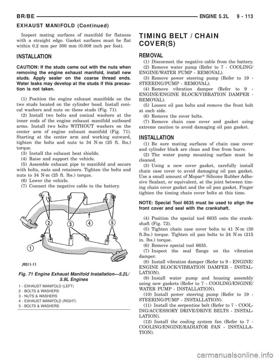
(1) Position the engine exhaust manifolds on the
two studs located on the cylinder head. Install coni-
cal washers and nuts on these studs (Fig. 71).
(2) Install two bolts and conical washers at the
inner ends of the engine exhaust manifold outboard
arms. Install two bolts WITHOUT washers on the
center arm of engine exhaust manifold (Fig. 71).
Starting at the center arm and working outward,
tighten the bolts and nuts to 34 N´m (25 ft. lbs.)
torque.
(3) Install the exhaust heat shields.
(4) Raise and support the vehicle.
(5) Assemble exhaust pipe to manifold and secure
with bolts, nuts and retainers. Tighten the bolts and
nuts to 34 N´m (25 ft. lbs.) torque.
(6) Lower the vehicle.
(7) Connect the negative cable to the battery.
TIMING BELT / CHAIN
COVER(S)
REMOVAL
(1) Disconnect the negative cable from the battery.
(2) Remove water pump (Refer to 7 - COOLING/
ENGINE/WATER PUMP - REMOVAL).
(3) Remove power steering pump (Refer to 19 -
STEERING/PUMP - REMOVAL).
(4) Remove vibration damper (Refer to 9 -
ENGINE/ENGINE BLOCK/VIBRATION DAMPER -
REMOVAL).
(5) Loosen oil pan bolts and remove the front bolt
at each side.
(6) Remove the cover bolts.
(7) Remove chain case cover and gasket using
extreme caution to avoid damaging oil pan gasket.
INSTALLATION
(1) Be sure mating surfaces of chain case cover
and cylinder block are clean and free from burrs.
(2) The water pump mounting surface must be
cleaned.
(3) Using a new cover gasket, carefully install
chain case cover to avoid damaging oil pan gasket.
Use a small amount of MopartSilicone Rubber Adhe-
sive Sealant, or equivalent, at the joint between tim-
ing chain cover gasket and the oil pan gasket. Finger
tighten the timing chain cover bolts at this time.
NOTE: Special Tool 6635 must be used to align the
front cover and seal with the crankshaft.
(4) Position the special tool 6635 onto the crank-
shaft (Fig. 72).
(5) Tighten chain case cover bolts to 41 N´m (30
ft.lbs.) torque. Tighten oil pan bolts to 24 N´m (215
in. lbs.) torque.
(6) Remove special tool 6635.
(7) Inspect the seal flange on the vibration
damper.
(8) Install vibration damper (Refer to 9 - ENGINE/
ENGINE BLOCK/VIBRATION DAMPER - INSTAL-
LATION).
(9) Install water pump and housing assembly
using new gaskets (Refer to 7 - COOLING/ENGINE/
WATER PUMP - INSTALLATION).
(10) Install power steering pump (Refer to 19 -
STEERING/PUMP - INSTALLATION).
(11) Install the serpentine belt (Refer to 7 - COOL-
ING/ACCESSORY DRIVE/DRIVE BELTS - INSTAL-
LATION).
(12) Install the cooling system fan (Refer to 7 -
COOLING/ENGINE/RADIATOR FAN - INSTALLA-
TION).
Fig. 71 Engine Exhaust Manifold InstallationÐ5.2L/
5.9L Engines
1 - EXHAUST MANIFOLD (LEFT)
2 - BOLTS & WASHERS
3 - NUTS & WASHERS
4 - EXHAUST MANIFOLD (RIGHT)
5 - BOLTS & WASHERS
BR/BEENGINE 5.2L 9 - 113
EXHAUST MANIFOLD (Continued)
Page 1266 of 2889
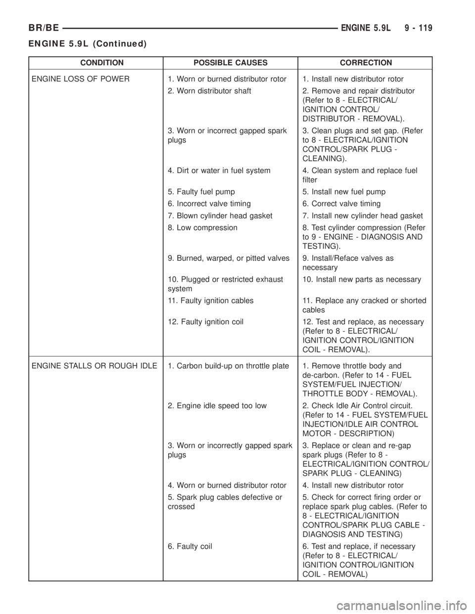
CONDITION POSSIBLE CAUSES CORRECTION
ENGINE LOSS OF POWER 1. Worn or burned distributor rotor 1. Install new distributor rotor
2. Worn distributor shaft 2. Remove and repair distributor
(Refer to 8 - ELECTRICAL/
IGNITION CONTROL/
DISTRIBUTOR - REMOVAL).
3. Worn or incorrect gapped spark
plugs3. Clean plugs and set gap. (Refer
to 8 - ELECTRICAL/IGNITION
CONTROL/SPARK PLUG -
CLEANING).
4. Dirt or water in fuel system 4. Clean system and replace fuel
filter
5. Faulty fuel pump 5. Install new fuel pump
6. Incorrect valve timing 6. Correct valve timing
7. Blown cylinder head gasket 7. Install new cylinder head gasket
8. Low compression 8. Test cylinder compression (Refer
to 9 - ENGINE - DIAGNOSIS AND
TESTING).
9. Burned, warped, or pitted valves 9. Install/Reface valves as
necessary
10. Plugged or restricted exhaust
system10. Install new parts as necessary
11. Faulty ignition cables 11. Replace any cracked or shorted
cables
12. Faulty ignition coil 12. Test and replace, as necessary
(Refer to 8 - ELECTRICAL/
IGNITION CONTROL/IGNITION
COIL - REMOVAL).
ENGINE STALLS OR ROUGH IDLE 1. Carbon build-up on throttle plate 1. Remove throttle body and
de-carbon. (Refer to 14 - FUEL
SYSTEM/FUEL INJECTION/
THROTTLE BODY - REMOVAL).
2. Engine idle speed too low 2. Check Idle Air Control circuit.
(Refer to 14 - FUEL SYSTEM/FUEL
INJECTION/IDLE AIR CONTROL
MOTOR - DESCRIPTION)
3. Worn or incorrectly gapped spark
plugs3. Replace or clean and re-gap
spark plugs (Refer to 8 -
ELECTRICAL/IGNITION CONTROL/
SPARK PLUG - CLEANING)
4. Worn or burned distributor rotor 4. Install new distributor rotor
5. Spark plug cables defective or
crossed5. Check for correct firing order or
replace spark plug cables. (Refer to
8 - ELECTRICAL/IGNITION
CONTROL/SPARK PLUG CABLE -
DIAGNOSIS AND TESTING)
6. Faulty coil 6. Test and replace, if necessary
(Refer to 8 - ELECTRICAL/
IGNITION CONTROL/IGNITION
COIL - REMOVAL)
BR/BEENGINE 5.9L 9 - 119
ENGINE 5.9L (Continued)
Page 1280 of 2889
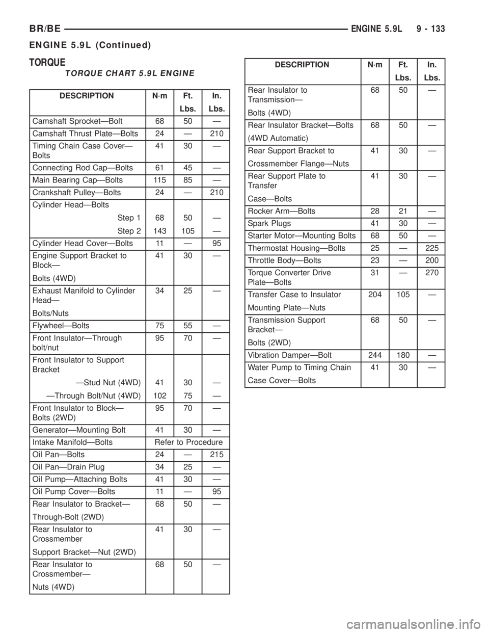
TORQUE
TORQUE CHART 5.9L ENGINE
DESCRIPTION N´m Ft. In.
Lbs. Lbs.
Camshaft SprocketÐBolt 68 50 Ð
Camshaft Thrust PlateÐBolts 24 Ð 210
Timing Chain Case CoverÐ
Bolts41 30 Ð
Connecting Rod CapÐBolts 61 45 Ð
Main Bearing CapÐBolts 115 85 Ð
Crankshaft PulleyÐBolts 24 Ð 210
Cylinder HeadÐBolts
Step 1 68 50 Ð
Step 2 143 105 Ð
Cylinder Head CoverÐBolts 11 Ð 95
Engine Support Bracket to
BlockÐ41 30 Ð
Bolts (4WD)
Exhaust Manifold to Cylinder
HeadÐ34 25 Ð
Bolts/Nuts
FlywheelÐBolts 75 55 Ð
Front InsulatorÐThrough
bolt/nut95 70 Ð
Front Insulator to Support
Bracket
ÐStud Nut (4WD) 41 30 Ð
ÐThrough Bolt/Nut (4WD) 102 75 Ð
Front Insulator to BlockÐ
Bolts (2WD)95 70 Ð
GeneratorÐMounting Bolt 41 30 Ð
Intake ManifoldÐBolts Refer to Procedure
Oil PanÐBolts 24 Ð 215
Oil PanÐDrain Plug 34 25 Ð
Oil PumpÐAttaching Bolts 41 30 Ð
Oil Pump CoverÐBolts 11 Ð 95
Rear Insulator to BracketÐ 68 50 Ð
Through-Bolt (2WD)
Rear Insulator to
Crossmember41 30 Ð
Support BracketÐNut (2WD)
Rear Insulator to
CrossmemberÐ68 50 Ð
Nuts (4WD)
DESCRIPTION N´m Ft. In.
Lbs. Lbs.
Rear Insulator to
TransmissionÐ68 50 Ð
Bolts (4WD)
Rear Insulator BracketÐBolts 68 50 Ð
(4WD Automatic)
Rear Support Bracket to 41 30 Ð
Crossmember FlangeÐNuts
Rear Support Plate to
Transfer41 30 Ð
CaseÐBolts
Rocker ArmÐBolts 28 21 Ð
Spark Plugs 41 30 Ð
Starter MotorÐMounting Bolts 68 50 Ð
Thermostat HousingÐBolts 25 Ð 225
Throttle BodyÐBolts 23 Ð 200
Torque Converter Drive
PlateÐBolts31 Ð 270
Transfer Case to Insulator 204 105 Ð
Mounting PlateÐNuts
Transmission Support
BracketÐ68 50 Ð
Bolts (2WD)
Vibration DamperÐBolt 244 180 Ð
Water Pump to Timing Chain 41 30 Ð
Case CoverÐBolts
BR/BEENGINE 5.9L 9 - 133
ENGINE 5.9L (Continued)
Page 1299 of 2889
NOTE: Worn valve guides or cocked springs are
sometimes mistaken for noisy tappets. If such is the
case, noise may be dampened by applying side thrust
on the valve spring. If noise is not appreciably
reduced, it can be assumed the noise is in the tappet.
Inspect the rocker arm push rod sockets and push rod
ends for wear.
(3)Valve tappet noise ranges from light noise to a
heavy click. A light noise is usually caused by excessive
leak-down around the unit plunger, or by the plunger
partially sticking in the tappet body cylinder. The tap-
pet should be replaced. A heavy click is caused by a tap-
pet check valve not seating, or by foreign particles
wedged between the plunger and the tappet body. This
will cause the plunger to stick in the down position.
This heavy click will be accompanied by excessive clear-
ance between the valve stem and rocker arm as valve
closes. In either case, tappet assembly should be
removed for inspection and cleaning.
(4) The valve train generates a noise very much
like a light tappet noise during normal operation.
Care must be taken to ensure that tappets are mak-
ing the noise. If more than one tappet seems to be
noisy, it's probably not the tappets.
LEAK-DOWN TEST
After cleaning and inspection, test each tappet for
specified leak-down rate tolerance to ensure zero-lash
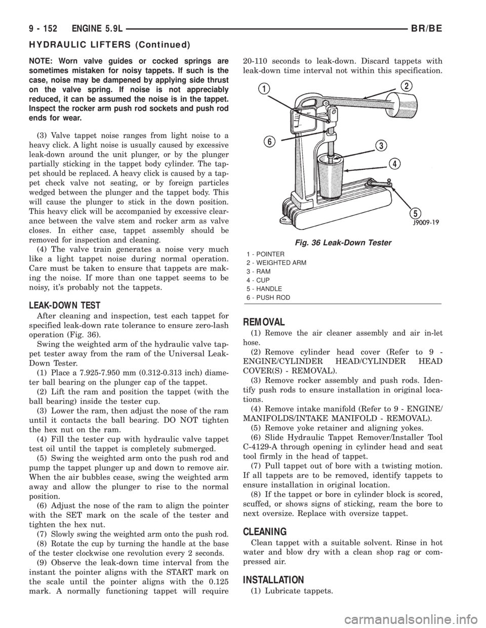
operation (Fig. 36).
Swing the weighted arm of the hydraulic valve tap-
pet tester away from the ram of the Universal Leak-
Down Tester.
(1)
Place a 7.925-7.950 mm (0.312-0.313 inch) diame-
ter ball bearing on the plunger cap of the tappet.
(2) Lift the ram and position the tappet (with the
ball bearing) inside the tester cup.
(3) Lower the ram, then adjust the nose of the ram
until it contacts the ball bearing. DO NOT tighten
the hex nut on the ram.
(4) Fill the tester cup with hydraulic valve tappet
test oil until the tappet is completely submerged.
(5) Swing the weighted arm onto the push rod and
pump the tappet plunger up and down to remove air.
When the air bubbles cease, swing the weighted arm
away and allow the plunger to rise to the normal
position.
(6) Adjust the nose of the ram to align the pointer
with the SET mark on the scale of the tester and
tighten the hex nut.
(7)
Slowly swing the weighted arm onto the push rod.
(8)Rotate the cup by turning the handle at the base
of the tester clockwise one revolution every 2 seconds.
(9) Observe the leak-down time interval from the
instant the pointer aligns with the START mark on
the scale until the pointer aligns with the 0.125
mark. A normally functioning tappet will require20-110 seconds to leak-down. Discard tappets with
leak-down time interval not within this specification.
REMOVAL
(1)Remove the air cleaner assembly and air in-let
hose.
(2) Remove cylinder head cover (Refer to 9 -
ENGINE/CYLINDER HEAD/CYLINDER HEAD
COVER(S) - REMOVAL).
(3) Remove rocker assembly and push rods. Iden-
tify push rods to ensure installation in original loca-
tions.
(4) Remove intake manifold (Refer to 9 - ENGINE/
MANIFOLDS/INTAKE MANIFOLD - REMOVAL).
(5) Remove yoke retainer and aligning yokes.
(6) Slide Hydraulic Tappet Remover/Installer Tool
C-4129-A through opening in cylinder head and seat
tool firmly in the head of tappet.
(7) Pull tappet out of bore with a twisting motion.
If all tappets are to be removed, identify tappets to
ensure installation in original location.
(8) If the tappet or bore in cylinder block is scored,
scuffed, or shows signs of sticking, ream the bore to
next oversize. Replace with oversize tappet.
CLEANING
Clean tappet with a suitable solvent. Rinse in hot
water and blow dry with a clean shop rag or com-
pressed air.
INSTALLATION
(1) Lubricate tappets.
Fig. 36 Leak-Down Tester
1 - POINTER
2 - WEIGHTED ARM
3 - RAM
4 - CUP
5 - HANDLE
6 - PUSH ROD
9 - 152 ENGINE 5.9LBR/BE
HYDRAULIC LIFTERS (Continued)
Page 1312 of 2889
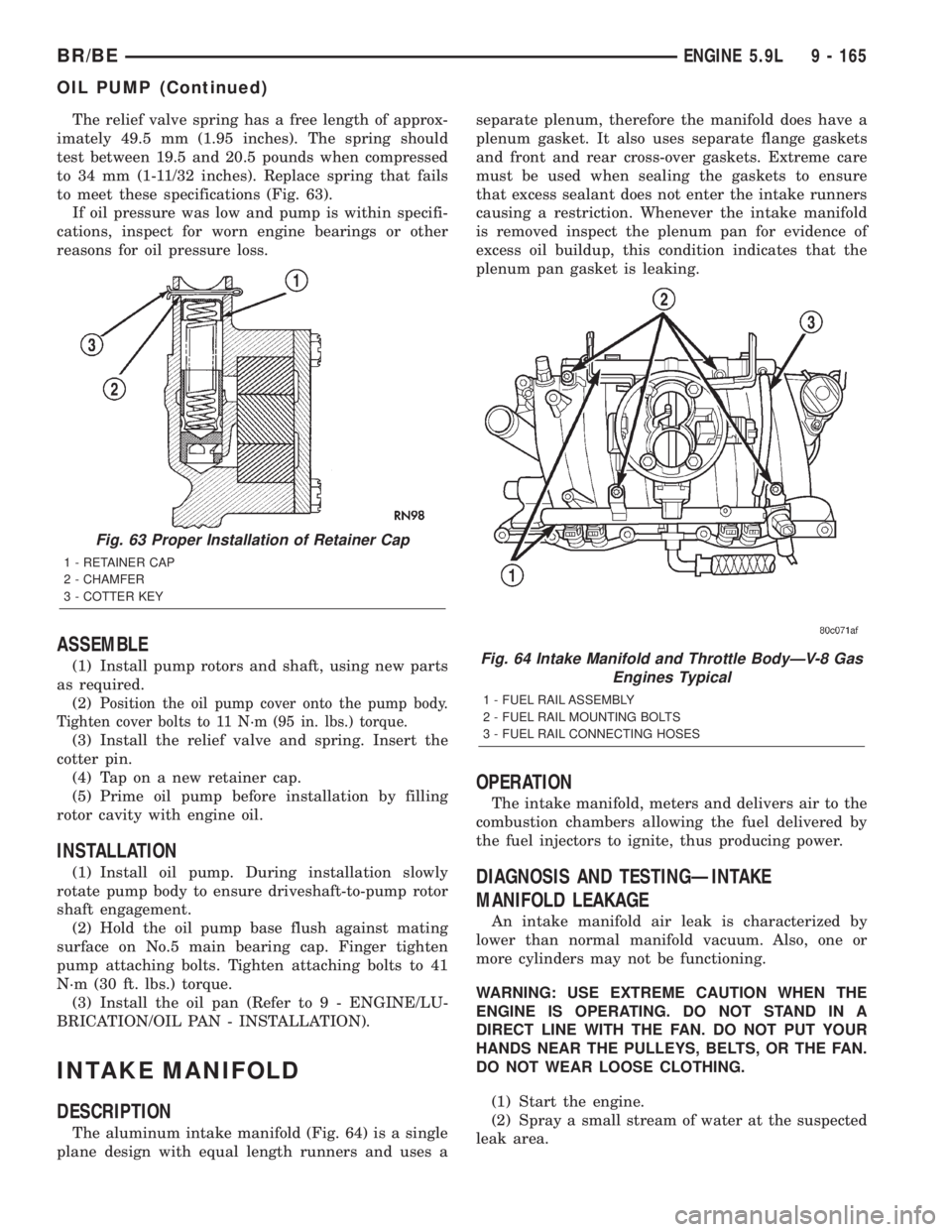
The relief valve spring has a free length of approx-
imately 49.5 mm (1.95 inches). The spring should
test between 19.5 and 20.5 pounds when compressed
to 34 mm (1-11/32 inches). Replace spring that fails
to meet these specifications (Fig. 63).
If oil pressure was low and pump is within specifi-
cations, inspect for worn engine bearings or other
reasons for oil pressure loss.
ASSEMBLE
(1) Install pump rotors and shaft, using new parts
as required.
(2)
Position the oil pump cover onto the pump body.
Tighten cover bolts to 11 N´m (95 in. lbs.) torque.
(3) Install the relief valve and spring. Insert the
cotter pin.
(4) Tap on a new retainer cap.
(5) Prime oil pump before installation by filling
rotor cavity with engine oil.
INSTALLATION
(1) Install oil pump. During installation slowly
rotate pump body to ensure driveshaft-to-pump rotor
shaft engagement.
(2) Hold the oil pump base flush against mating
surface on No.5 main bearing cap. Finger tighten
pump attaching bolts. Tighten attaching bolts to 41
N´m (30 ft. lbs.) torque.
(3) Install the oil pan (Refer to 9 - ENGINE/LU-
BRICATION/OIL PAN - INSTALLATION).
INTAKE MANIFOLD
DESCRIPTION
The aluminum intake manifold (Fig. 64) is a single
plane design with equal length runners and uses aseparate plenum, therefore the manifold does have a
plenum gasket. It also uses separate flange gaskets
and front and rear cross-over gaskets. Extreme care
must be used when sealing the gaskets to ensure
that excess sealant does not enter the intake runners
causing a restriction. Whenever the intake manifold
is removed inspect the plenum pan for evidence of
excess oil buildup, this condition indicates that the
plenum pan gasket is leaking.
OPERATION
The intake manifold, meters and delivers air to the
combustion chambers allowing the fuel delivered by
the fuel injectors to ignite, thus producing power.
DIAGNOSIS AND TESTINGÐINTAKE
MANIFOLD LEAKAGE
An intake manifold air leak is characterized by
lower than normal manifold vacuum. Also, one or
more cylinders may not be functioning.
WARNING: USE EXTREME CAUTION WHEN THE
ENGINE IS OPERATING. DO NOT STAND IN A
DIRECT LINE WITH THE FAN. DO NOT PUT YOUR
HANDS NEAR THE PULLEYS, BELTS, OR THE FAN.
DO NOT WEAR LOOSE CLOTHING.
(1) Start the engine.
(2) Spray a small stream of water at the suspected
leak area.
Fig. 63 Proper Installation of Retainer Cap
1 - RETAINER CAP
2 - CHAMFER
3 - COTTER KEY
Fig. 64 Intake Manifold and Throttle BodyÐV-8 Gas
Engines Typical
1 - FUEL RAIL ASSEMBLY
2 - FUEL RAIL MOUNTING BOLTS
3 - FUEL RAIL CONNECTING HOSES
BR/BEENGINE 5.9L 9 - 165
OIL PUMP (Continued)
Page 1316 of 2889
(6) Lower the vehicle.
(7) Connect the negative cable to the battery.
TIMING BELT / CHAIN
COVER(S)
REMOVAL
(1) Disconnect the negative cable from the battery.
(2) Remove water pump (Refer to 7 - COOLING/
ENGINE/WATER PUMP - REMOVAL).
(3) Remove power steering pump (Refer to 19 -
STEERING/PUMP - REMOVAL).
(4) Remove vibration damper (Refer to 9 -
ENGINE/ENGINE BLOCK/VIBRATION DAMPER -
REMOVAL).
(5) Loosen oil pan bolts and remove the front bolt
at each side.
(6) Remove the cover bolts.
(7) Remove chain case cover and gasket using
extreme caution to avoid damaging oil pan gasket.
INSTALLATION
(1) Be sure mating surfaces of chain case cover
and cylinder block are clean and free from burrs.
(2) The water pump mounting surface must be
cleaned.
(3) Using a new cover gasket, carefully install
chain case cover to avoid damaging oil pan gasket.
Use a small amount of MopartSilicone Rubber Adhe-
sive Sealant, or equivalent, at the joint between tim-
ing chain cover gasket and the oil pan gasket. Finger
tighten the timing chain cover bolts at this time.NOTE: Special Tool 6635 must be used to align the
front cover and seal with the crankshaft.
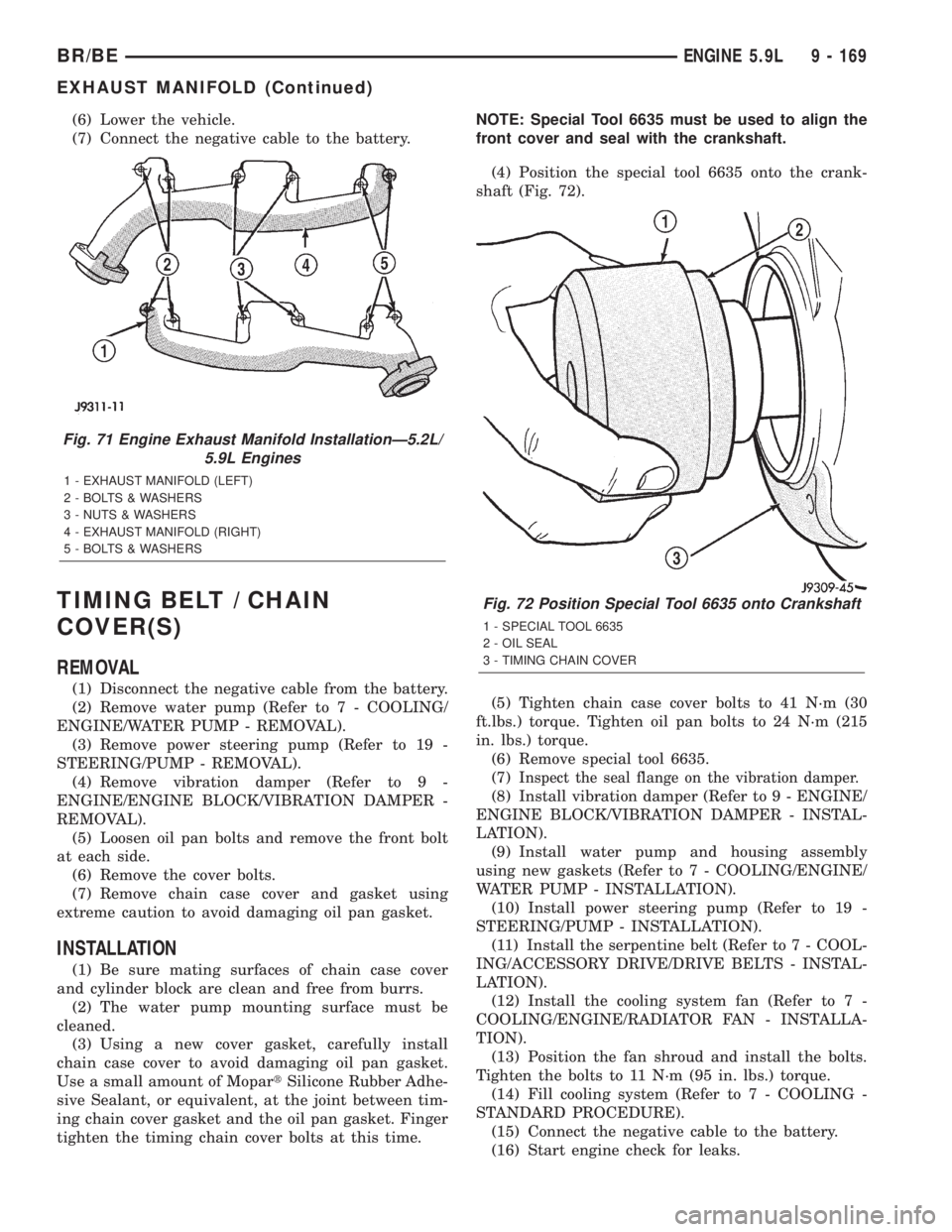
(4) Position the special tool 6635 onto the crank-
shaft (Fig. 72).
(5) Tighten chain case cover bolts to 41 N´m (30
ft.lbs.) torque. Tighten oil pan bolts to 24 N´m (215
in. lbs.) torque.
(6) Remove special tool 6635.
(7)
Inspect the seal flange on the vibration damper.
(8) Install vibration damper (Refer to 9 - ENGINE/
ENGINE BLOCK/VIBRATION DAMPER - INSTAL-
LATION).
(9) Install water pump and housing assembly
using new gaskets (Refer to 7 - COOLING/ENGINE/
WATER PUMP - INSTALLATION).
(10) Install power steering pump (Refer to 19 -
STEERING/PUMP - INSTALLATION).
(11) Install the serpentine belt (Refer to 7 - COOL-
ING/ACCESSORY DRIVE/DRIVE BELTS - INSTAL-
LATION).
(12) Install the cooling system fan (Refer to 7 -
COOLING/ENGINE/RADIATOR FAN - INSTALLA-
TION).
(13) Position the fan shroud and install the bolts.
Tighten the bolts to 11 N´m (95 in. lbs.) torque.
(14) Fill cooling system (Refer to 7 - COOLING -
STANDARD PROCEDURE).
(15) Connect the negative cable to the battery.
(16) Start engine check for leaks.
Fig. 71 Engine Exhaust Manifold InstallationÐ5.2L/
5.9L Engines
1 - EXHAUST MANIFOLD (LEFT)
2 - BOLTS & WASHERS
3 - NUTS & WASHERS
4 - EXHAUST MANIFOLD (RIGHT)
5 - BOLTS & WASHERS
Fig. 72 Position Special Tool 6635 onto Crankshaft
1 - SPECIAL TOOL 6635
2 - OIL SEAL
3 - TIMING CHAIN COVER
BR/BEENGINE 5.9L 9 - 169
EXHAUST MANIFOLD (Continued)
Page 1321 of 2889
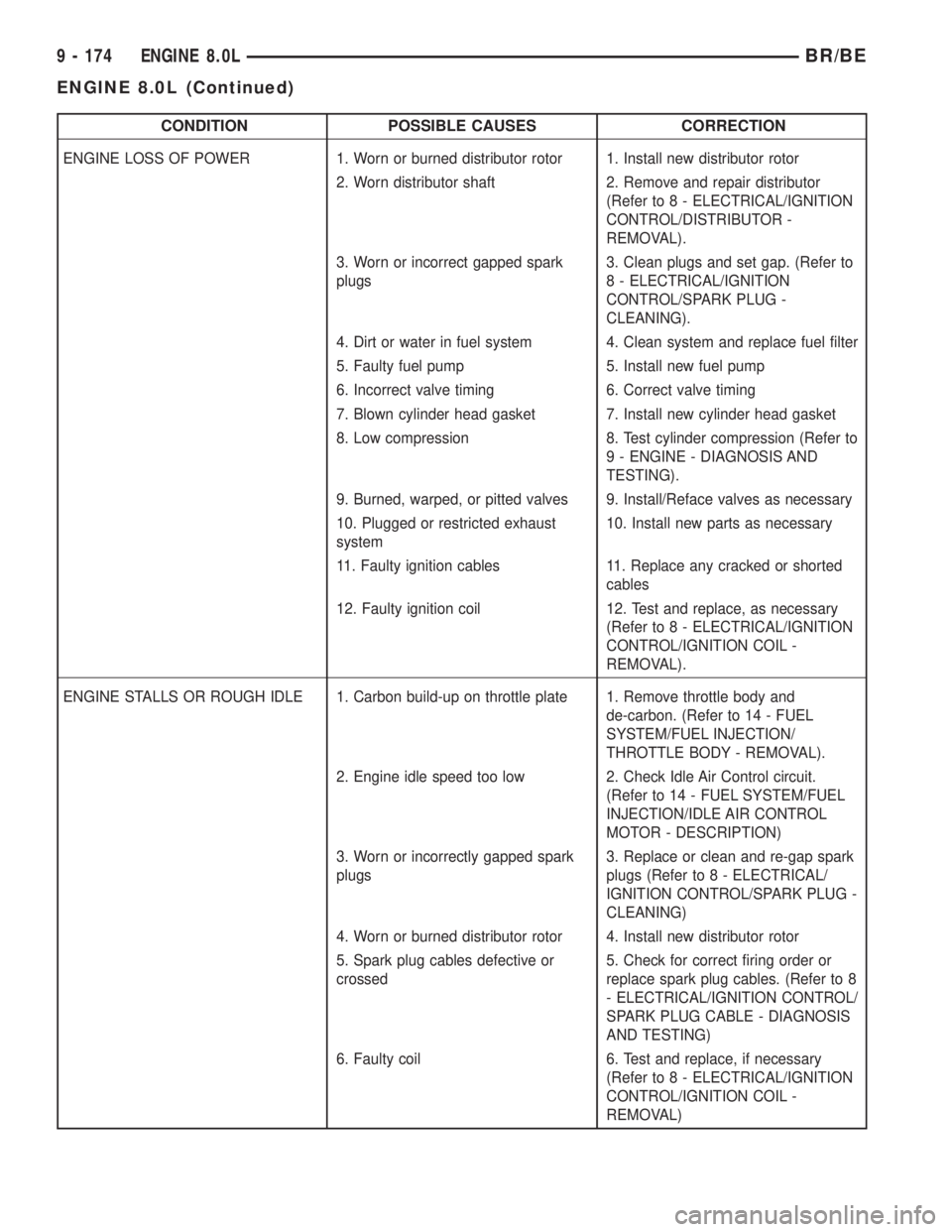
CONDITION POSSIBLE CAUSES CORRECTION
ENGINE LOSS OF POWER 1. Worn or burned distributor rotor 1. Install new distributor rotor
2. Worn distributor shaft 2. Remove and repair distributor
(Refer to 8 - ELECTRICAL/IGNITION
CONTROL/DISTRIBUTOR -
REMOVAL).
3. Worn or incorrect gapped spark
plugs3. Clean plugs and set gap. (Refer to
8 - ELECTRICAL/IGNITION
CONTROL/SPARK PLUG -
CLEANING).
4. Dirt or water in fuel system 4. Clean system and replace fuel filter
5. Faulty fuel pump 5. Install new fuel pump
6. Incorrect valve timing 6. Correct valve timing
7. Blown cylinder head gasket 7. Install new cylinder head gasket
8. Low compression 8. Test cylinder compression (Refer to
9 - ENGINE - DIAGNOSIS AND
TESTING).
9. Burned, warped, or pitted valves 9. Install/Reface valves as necessary
10. Plugged or restricted exhaust
system10. Install new parts as necessary
11. Faulty ignition cables 11. Replace any cracked or shorted
cables
12. Faulty ignition coil 12. Test and replace, as necessary
(Refer to 8 - ELECTRICAL/IGNITION
CONTROL/IGNITION COIL -
REMOVAL).
ENGINE STALLS OR ROUGH IDLE 1. Carbon build-up on throttle plate 1. Remove throttle body and
de-carbon. (Refer to 14 - FUEL
SYSTEM/FUEL INJECTION/
THROTTLE BODY - REMOVAL).
2. Engine idle speed too low 2. Check Idle Air Control circuit.
(Refer to 14 - FUEL SYSTEM/FUEL
INJECTION/IDLE AIR CONTROL
MOTOR - DESCRIPTION)
3. Worn or incorrectly gapped spark
plugs3. Replace or clean and re-gap spark
plugs (Refer to 8 - ELECTRICAL/
IGNITION CONTROL/SPARK PLUG -
CLEANING)
4. Worn or burned distributor rotor 4. Install new distributor rotor
5. Spark plug cables defective or
crossed5. Check for correct firing order or
replace spark plug cables. (Refer to 8
- ELECTRICAL/IGNITION CONTROL/
SPARK PLUG CABLE - DIAGNOSIS
AND TESTING)
6. Faulty coil 6. Test and replace, if necessary
(Refer to 8 - ELECTRICAL/IGNITION
CONTROL/IGNITION COIL -
REMOVAL)
9 - 174 ENGINE 8.0LBR/BE
ENGINE 8.0L (Continued)
Page 1334 of 2889
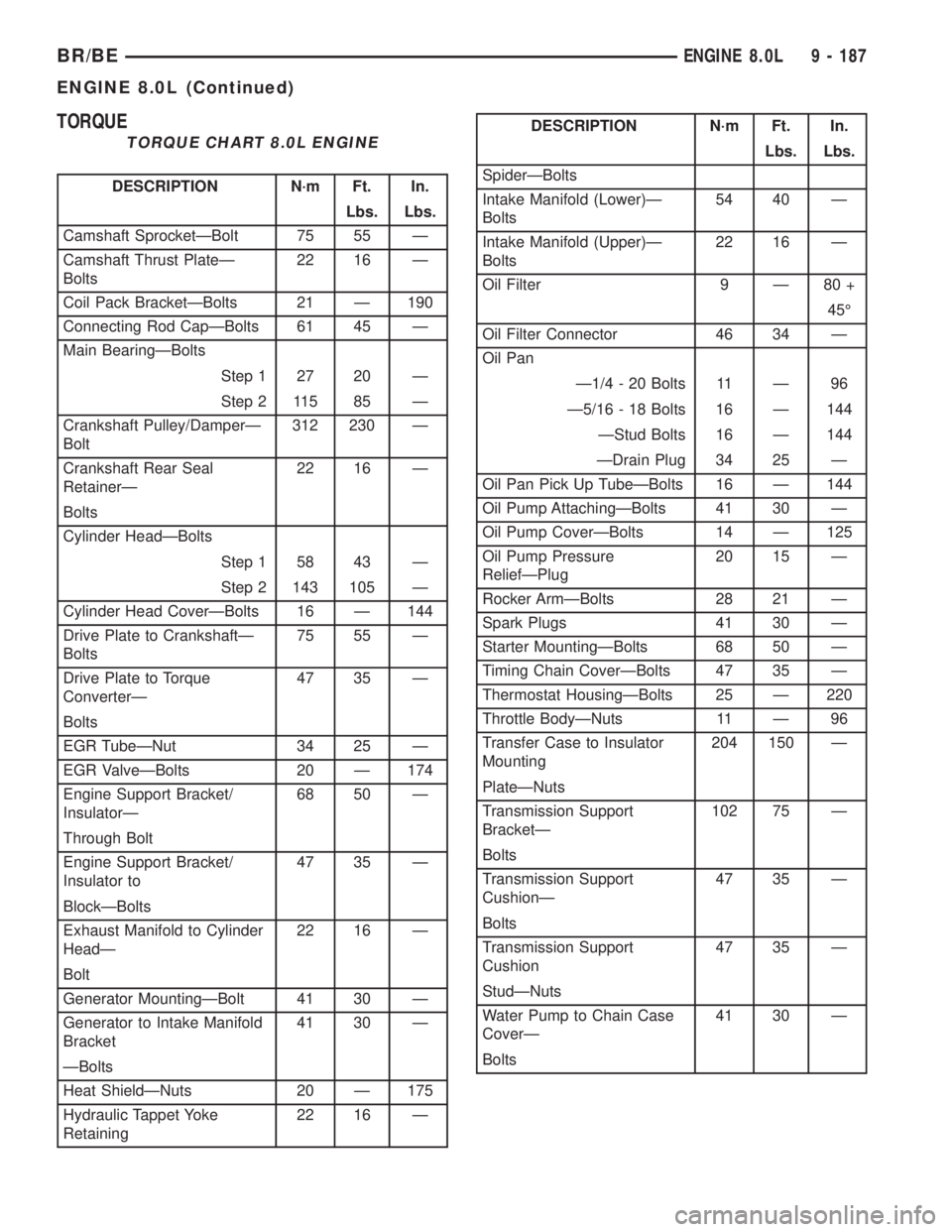
TORQUE
TORQUE CHART 8.0L ENGINE
DESCRIPTION N´m Ft. In.
Lbs. Lbs.
Camshaft SprocketÐBolt 75 55 Ð
Camshaft Thrust PlateÐ
Bolts22 16 Ð
Coil Pack BracketÐBolts 21 Ð 190
Connecting Rod CapÐBolts 61 45 Ð
Main BearingÐBolts
Step 1 27 20 Ð
Step 2 115 85 Ð
Crankshaft Pulley/DamperÐ
Bolt312 230 Ð
Crankshaft Rear Seal
RetainerÐ22 16 Ð
Bolts
Cylinder HeadÐBolts
Step 1 58 43 Ð
Step 2 143 105 Ð
Cylinder Head CoverÐBolts 16 Ð 144
Drive Plate to CrankshaftÐ
Bolts75 55 Ð
Drive Plate to Torque
ConverterÐ47 35 Ð
Bolts
EGR TubeÐNut 34 25 Ð
EGR ValveÐBolts 20 Ð 174
Engine Support Bracket/
InsulatorÐ68 50 Ð
Through Bolt
Engine Support Bracket/
Insulator to47 35 Ð
BlockÐBolts
Exhaust Manifold to Cylinder
HeadÐ22 16 Ð
Bolt
Generator MountingÐBolt 41 30 Ð
Generator to Intake Manifold
Bracket41 30 Ð
ÐBolts
Heat ShieldÐNuts 20 Ð 175
Hydraulic Tappet Yoke
Retaining22 16 Ð
DESCRIPTION N´m Ft. In.
Lbs. Lbs.
SpiderÐBolts
Intake Manifold (Lower)Ð
Bolts54 40 Ð
Intake Manifold (Upper)Ð
Bolts22 16 Ð
Oil Filter 9 Ð 80 +
45É
Oil Filter Connector 46 34 Ð
Oil Pan
Ð1/4 - 20 Bolts 11 Ð 96
Ð5/16 - 18 Bolts 16 Ð 144
ÐStud Bolts 16 Ð 144
ÐDrain Plug 34 25 Ð
Oil Pan Pick Up TubeÐBolts 16 Ð 144
Oil Pump AttachingÐBolts 41 30 Ð
Oil Pump CoverÐBolts 14 Ð 125
Oil Pump Pressure
ReliefÐPlug20 15 Ð
Rocker ArmÐBolts 28 21 Ð
Spark Plugs 41 30 Ð
Starter MountingÐBolts 68 50 Ð
Timing Chain CoverÐBolts 47 35 Ð
Thermostat HousingÐBolts 25 Ð 220
Throttle BodyÐNuts 11 Ð 96
Transfer Case to Insulator
Mounting204 150 Ð
PlateÐNuts
Transmission Support
BracketÐ102 75 Ð
Bolts
Transmission Support
CushionÐ47 35 Ð
Bolts
Transmission Support
Cushion47 35 Ð
StudÐNuts
Water Pump to Chain Case
CoverÐ41 30 Ð
Bolts
BR/BEENGINE 8.0L 9 - 187
ENGINE 8.0L (Continued)
Page 1369 of 2889
(2) Position the oil pump cover onto the timing
chain cover. Tighten cover screws to 14 N´m (125 in.
lbs.) torque.
(3) Make sure that inner ring moves freely after
cover is installed.
(4) Install the timing chain cover (Refer to 9 -
ENGINE/VALVE TIMING/TIMING BELT / CHAIN
COVER(S) - INSTALLATION).
(5) Squirt oil into relief valve hole until oil runs
out.
(6) Install the relief valve and spring.
(7) Using a new pressure relief valve gasket,
install the relief valve plug. Tighten the plug to 20
N´m (15 ft. lbs.) torque.
(8) Install oil filter that has been filled with oil.
INTAKE MANIFOLD
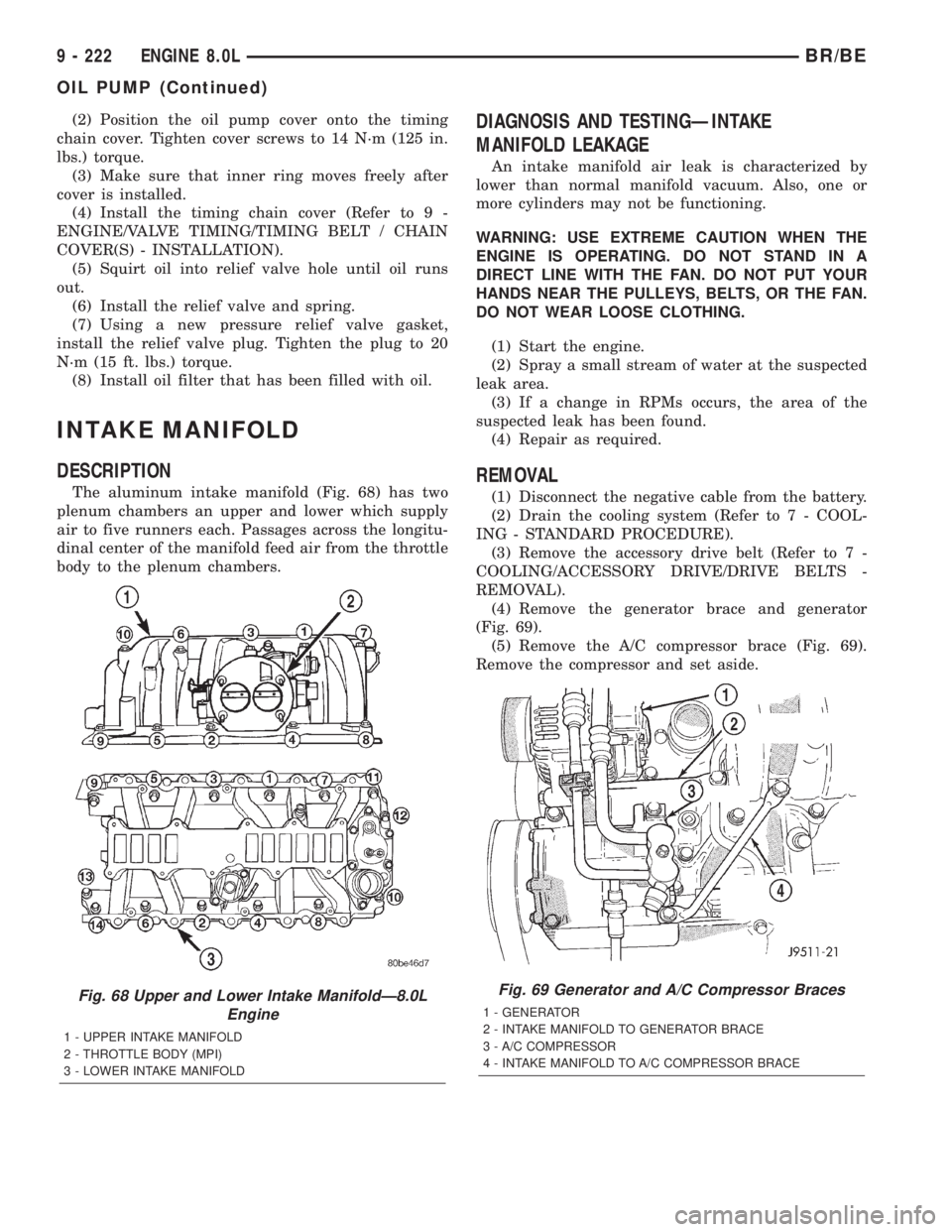
DESCRIPTION
The aluminum intake manifold (Fig. 68) has two
plenum chambers an upper and lower which supply
air to five runners each. Passages across the longitu-
dinal center of the manifold feed air from the throttle
body to the plenum chambers.
DIAGNOSIS AND TESTINGÐINTAKE
MANIFOLD LEAKAGE
An intake manifold air leak is characterized by
lower than normal manifold vacuum. Also, one or
more cylinders may not be functioning.
WARNING: USE EXTREME CAUTION WHEN THE
ENGINE IS OPERATING. DO NOT STAND IN A
DIRECT LINE WITH THE FAN. DO NOT PUT YOUR
HANDS NEAR THE PULLEYS, BELTS, OR THE FAN.
DO NOT WEAR LOOSE CLOTHING.
(1) Start the engine.
(2) Spray a small stream of water at the suspected
leak area.
(3) If a change in RPMs occurs, the area of the
suspected leak has been found.
(4) Repair as required.
REMOVAL
(1) Disconnect the negative cable from the battery.
(2) Drain the cooling system (Refer to 7 - COOL-
ING - STANDARD PROCEDURE).
(3) Remove the accessory drive belt (Refer to 7 -
COOLING/ACCESSORY DRIVE/DRIVE BELTS -
REMOVAL).
(4) Remove the generator brace and generator
(Fig. 69).
(5) Remove the A/C compressor brace (Fig. 69).
Remove the compressor and set aside.
Fig. 68 Upper and Lower Intake ManifoldÐ8.0L
Engine
1 - UPPER INTAKE MANIFOLD
2 - THROTTLE BODY (MPI)
3 - LOWER INTAKE MANIFOLD
Fig. 69 Generator and A/C Compressor Braces
1 - GENERATOR
2 - INTAKE MANIFOLD TO GENERATOR BRACE
3 - A/C COMPRESSOR
4 - INTAKE MANIFOLD TO A/C COMPRESSOR BRACE
9 - 222 ENGINE 8.0LBR/BE
OIL PUMP (Continued)
Page 1372 of 2889
exhaust gases to the exhaust pipes attached to the
manifolds.
REMOVAL
(1) Disconnect the negative cable from the battery.
(2) Raise and support the vehicle.
(3) Remove the bolts and nuts attaching the
exhaust pipe to the engine exhaust manifold..
(4) Lower the vehicle.
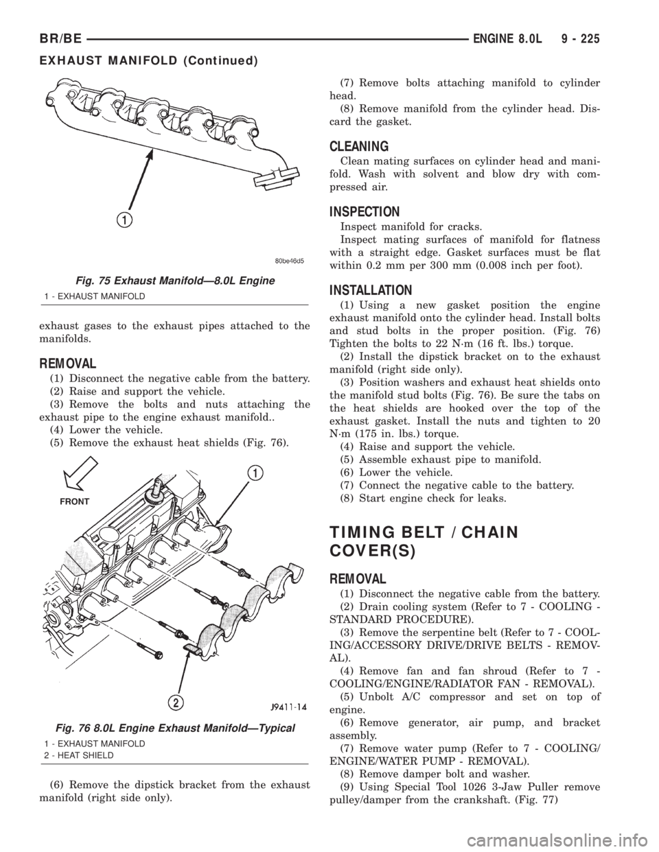
(5) Remove the exhaust heat shields (Fig. 76).
(6) Remove the dipstick bracket from the exhaust
manifold (right side only).(7) Remove bolts attaching manifold to cylinder
head.
(8) Remove manifold from the cylinder head. Dis-
card the gasket.
CLEANING
Clean mating surfaces on cylinder head and mani-
fold. Wash with solvent and blow dry with com-
pressed air.
INSPECTION
Inspect manifold for cracks.
Inspect mating surfaces of manifold for flatness
with a straight edge. Gasket surfaces must be flat
within 0.2 mm per 300 mm (0.008 inch per foot).
INSTALLATION
(1) Using a new gasket position the engine
exhaust manifold onto the cylinder head. Install bolts
and stud bolts in the proper position. (Fig. 76)
Tighten the bolts to 22 N´m (16 ft. lbs.) torque.
(2) Install the dipstick bracket on to the exhaust
manifold (right side only).
(3) Position washers and exhaust heat shields onto
the manifold stud bolts (Fig. 76). Be sure the tabs on
the heat shields are hooked over the top of the
exhaust gasket. Install the nuts and tighten to 20
N´m (175 in. lbs.) torque.
(4) Raise and support the vehicle.
(5) Assemble exhaust pipe to manifold.
(6) Lower the vehicle.
(7) Connect the negative cable to the battery.
(8) Start engine check for leaks.
TIMING BELT / CHAIN
COVER(S)
REMOVAL
(1) Disconnect the negative cable from the battery.
(2) Drain cooling system (Refer to 7 - COOLING -
STANDARD PROCEDURE).
(3) Remove the serpentine belt (Refer to 7 - COOL-
ING/ACCESSORY DRIVE/DRIVE BELTS - REMOV-
AL).
(4) Remove fan and fan shroud (Refer to 7 -
COOLING/ENGINE/RADIATOR FAN - REMOVAL).
(5) Unbolt A/C compressor and set on top of
engine.
(6) Remove generator, air pump, and bracket
assembly.
(7) Remove water pump (Refer to 7 - COOLING/
ENGINE/WATER PUMP - REMOVAL).
(8) Remove damper bolt and washer.
(9) Using Special Tool 1026 3-Jaw Puller remove
pulley/damper from the crankshaft. (Fig. 77)
Fig. 75 Exhaust ManifoldÐ8.0L Engine
1 - EXHAUST MANIFOLD
Fig. 76 8.0L Engine Exhaust ManifoldÐTypical
1 - EXHAUST MANIFOLD
2 - HEAT SHIELD
BR/BEENGINE 8.0L 9 - 225
EXHAUST MANIFOLD (Continued)