water pump DODGE RAM 2001 Service Manual PDF
[x] Cancel search | Manufacturer: DODGE, Model Year: 2001, Model line: RAM, Model: DODGE RAM 2001Pages: 2889, PDF Size: 68.07 MB
Page 838 of 2889
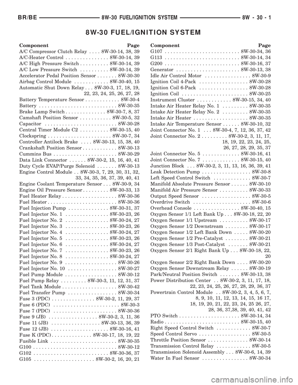
8W-30 FUEL/IGNITION SYSTEM
Component Page
A/C Compressor Clutch Relay.... 8W-30-14, 38, 39
A/C-Heater Control............... 8W-30-14, 39
A/C High Pressure Switch.......... 8W-30-14, 39
A/C Low Pressure Switch.......... 8W-30-14, 39
Accelerator Pedal Position Sensor....... 8W-30-30
Airbag Control Module............ 8W-30-40, 15
Automatic Shut Down Relay . . . 8W-30-3, 17, 18, 19,
22, 23, 24, 25, 26, 27, 28
Battery Temperature Sensor............ 8W-30-4
Battery........................... 8W-30-35
Brake Lamp Switch.............. 8W-30-7, 8, 37
Camshaft Position Sensor........... 8W-30-5, 32
Capacitor......................... 8W-30-28
Central Timer Module C2.......... 8W-30-15, 40
Clockspring...................... 8W-30-7, 34
Controller Antilock Brake.... 8W-30-13, 15, 38, 40
Crankshaft Position Sensor............ 8W-30-13
Cummins Bus...................... 8W-30-29
Data Link Connector...... 8W-30-2, 15, 16, 40, 41
Duty Cycle EVAP/Purge Solenoid....... 8W-30-13
Engine Control Module . . 8W-30-3, 7, 29, 30, 31, 32,
33, 34, 35, 36, 37, 39, 40, 41
Engine Coolant Temperature Sensor . . . 8W-30-9, 34
Engine Oil Pressure Sensor......... 8W-30-33, 13
Fuel Heater Relay................... 8W-30-36
Fuel Heater........................ 8W-30-36
Fuel Injection Pump.............. 8W-30-31, 37
Fuel Injector No. 1............... 8W-30-23, 26
Fuel Injector No. 2............... 8W-30-24, 27
Fuel Injector No. 3............... 8W-30-23, 26
Fuel Injector No. 4............... 8W-30-24, 27
Fuel Injector No. 5............... 8W-30-23, 26
Fuel Injector No. 6............... 8W-30-24, 27
Fuel Injector No. 7............... 8W-30-23, 26
Fuel Injector No. 8............... 8W-30-24, 27
Fuel Injector No. 9.................. 8W-30-26
Fuel Injector No. 10................. 8W-30-27
Fuel Pump Module.................. 8W-30-12
Fuel Pump Relay......... 8W-30-3, 11, 12, 31, 37
Fuel Tank Module................... 8W-30-42
Fuel Transfer Pump................. 8W-30-34
Fuse 3 (PDC)............... 8W-30-2, 11, 29, 37
Fuse 6 (PDC)....................... 8W-30-3
Fuse 7 (PDC)...................... 8W-30-36
Fuse 9 (JB)................. 8W-30-2, 3, 11, 36
Fuse 11 (JB)................. 8W-30-13, 36, 39
Fuse 12 (JB).................... 8W-30-16, 41
Fuse K (PDC).............. 8W-30-17, 18, 19, 22
Fusible Link....................... 8W-30-35
G100............................. 8W-30-12
G102.......................... 8W-30-36, 37
G105..................... 8W-30-2, 16, 20, 21Component Page
G107.......................... 8W-30-34, 36
G113 .......................... 8W-30-14, 34
G200.......................... 8W-30-16, 37
Generator...................... 8W-30-13, 38
Idle Air Control Motor................ 8W-30-9
Ignition Coil 4-Pack................. 8W-30-28
Ignition Coil 6-Pack................. 8W-30-28
Ignition Coil....................... 8W-30-25
Instrument Cluster............ 8W-30-15, 34, 40
Intake Air Heater Relay No. 1......... 8W-30-35
Intake Air Heater Relay No. 2......... 8W-30-35
Intake Air Heater................... 8W-30-35
Intake Air Temperature Sensor...... 8W-30-10, 32
Joint Connector No. 1 . . . 8W-30-4, 7, 12, 36, 37, 42
Joint Connector No. 2......... 8W-30-2, 3, 11, 17,
18, 19, 22, 23, 24, 25,
26, 27, 28, 29, 35, 37
Joint Connector No. 5............. 8W-30-16, 41
Joint Connector No. 7............. 8W-30-15, 40
Junction Block . . . 8W-30-2, 3, 11, 13, 16, 36, 39, 41
Leak Detection Pump................. 8W-30-8
Left Speed Control Switch............. 8W-30-7
Manifold Absolute Pressure Sensor...... 8W-30-10
Manifold Air Pressure Sensor.......... 8W-30-33
Output Speed Sensor................. 8W-30-5
Overdrive Switch.................... 8W-30-6
Overhead Console................ 8W-30-40, 15
Oxygen Sensor 1/1 Left Bank Up . . . 8W-30-18, 22, 20
Oxygen Sensor 1/1 Upstream.......... 8W-30-17
Oxygen Sensor 1/2 Downstream........ 8W-30-17
Oxygen Sensor 1/2 Left Bank Down..... 8W-30-20
Oxygen Sensor 1/2 Pre-Catalyst........ 8W-30-21
Oxygen Sensor 1/3 Post-Catalyst....... 8W-30-21
Oxygen Sensor 2/1 Right Bank Up . . . 8W-30-18, 22,
20
Oxygen Sensor 2/2 Right Bank Down.... 8W-30-20
Oxygen Sensor Downstream Relay...... 8W-30-19
Park/Neutral Position Switch....... 8W-30-13, 38
Power Distribution Center . . 8W-30-2, 3, 11, 17, 18,
22, 23, 24, 25, 26, 27, 28, 29, 36, 37
Powertrain Control Module . . 8W-30-2, 3, 4, 5, 6, 7,
8, 9, 10, 11, 12, 13, 14, 15, 16 17,
18, 19, 20, 21, 22, 23, 24, 25 26, 27,
28, 36, 37,38, 39, 40, 41, 42
PTO Switch..................... 8W-30-14, 34
Radio.......................... 8W-30-15, 40
Right Speed Control Switch............ 8W-30-7
Speed Control Servo.................. 8W-30-5
Throttle Position Sensor.............. 8W-30-14
Transmission Control Relay............ 8W-30-5
Transmission Solenoid Assembly . . . 8W-30-6, 14, 39
Water In Fuel Sensor................ 8W-30-34
BR/BE8W-30 FUEL/IGNITION SYSTEM 8W - 30 - 1
Page 1053 of 2889
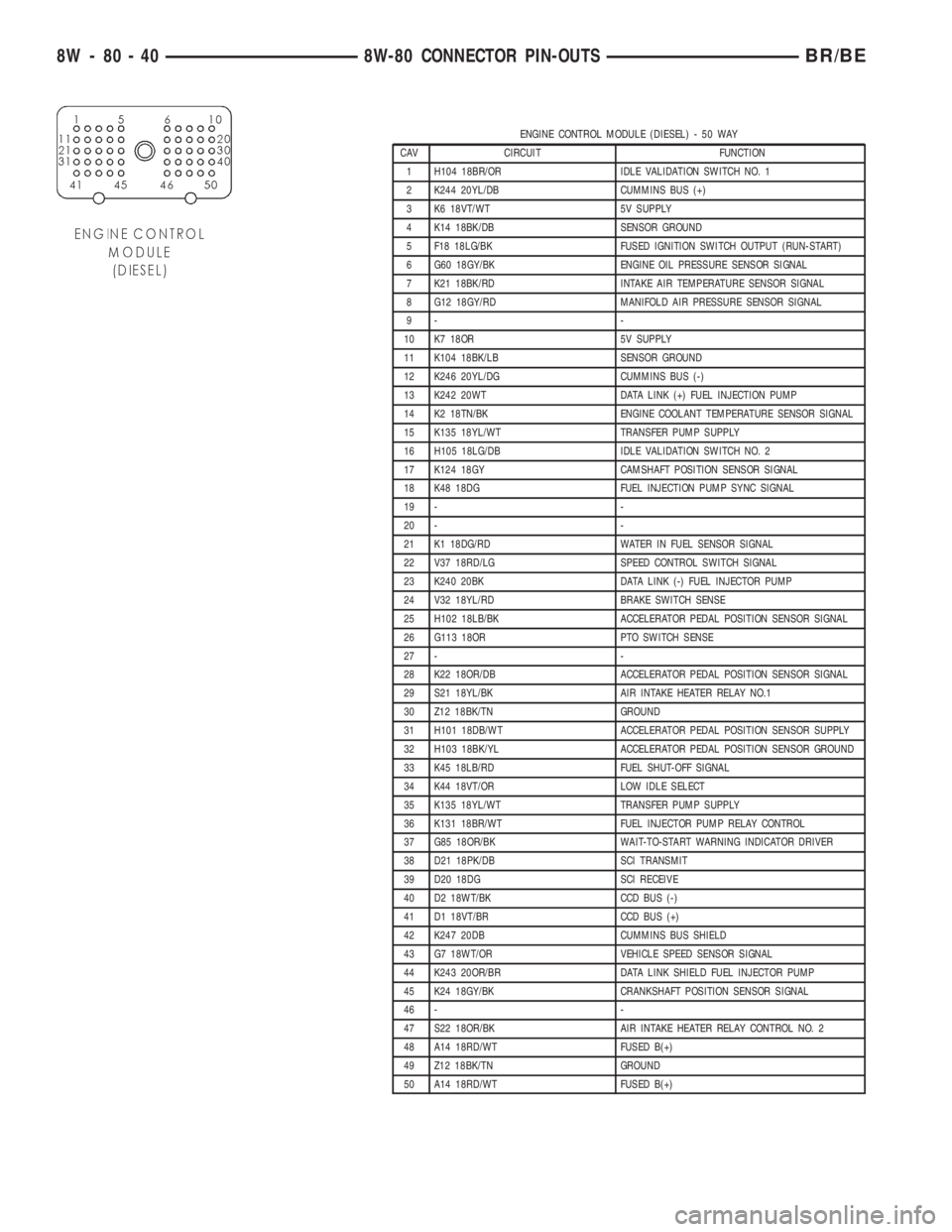
ENGINE CONTROL MODULE (DIESEL) - 50 WAY
CAV CIRCUIT FUNCTION
1 H104 18BR/OR IDLE VALIDATION SWITCH NO. 1
2 K244 20YL/DB CUMMINS BUS (+)
3 K6 18VT/WT 5V SUPPLY
4 K14 18BK/DB SENSOR GROUND
5 F18 18LG/BK FUSED IGNITION SWITCH OUTPUT (RUN-START)
6 G60 18GY/BK ENGINE OIL PRESSURE SENSOR SIGNAL
7 K21 18BK/RD INTAKE AIR TEMPERATURE SENSOR SIGNAL
8 G12 18GY/RD MANIFOLD AIR PRESSURE SENSOR SIGNAL
9- -
10 K7 18OR 5V SUPPLY
11 K104 18BK/LB SENSOR GROUND
12 K246 20YL/DG CUMMINS BUS (-)
13 K242 20WT DATA LINK (+) FUEL INJECTION PUMP
14 K2 18TN/BK ENGINE COOLANT TEMPERATURE SENSOR SIGNAL
15 K135 18YL/WT TRANSFER PUMP SUPPLY
16 H105 18LG/DB IDLE VALIDATION SWITCH NO. 2
17 K124 18GY CAMSHAFT POSITION SENSOR SIGNAL
18 K48 18DG FUEL INJECTION PUMP SYNC SIGNAL
19 - -
20 - -
21 K1 18DG/RD WATER IN FUEL SENSOR SIGNAL
22 V37 18RD/LG SPEED CONTROL SWITCH SIGNAL
23 K240 20BK DATA LINK (-) FUEL INJECTOR PUMP
24 V32 18YL/RD BRAKE SWITCH SENSE
25 H102 18LB/BK ACCELERATOR PEDAL POSITION SENSOR SIGNAL
26 G113 18OR PTO SWITCH SENSE
27 - -
28 K22 18OR/DB ACCELERATOR PEDAL POSITION SENSOR SIGNAL
29 S21 18YL/BK AIR INTAKE HEATER RELAY NO.1
30 Z12 18BK/TN GROUND
31 H101 18DB/WT ACCELERATOR PEDAL POSITION SENSOR SUPPLY
32 H103 18BK/YL ACCELERATOR PEDAL POSITION SENSOR GROUND
33 K45 18LB/RD FUEL SHUT-OFF SIGNAL
34 K44 18VT/OR LOW IDLE SELECT
35 K135 18YL/WT TRANSFER PUMP SUPPLY
36 K131 18BR/WT FUEL INJECTOR PUMP RELAY CONTROL
37 G85 18OR/BK WAIT-TO-START WARNING INDICATOR DRIVER
38 D21 18PK/DB SCI TRANSMIT
39 D20 18DG SCI RECEIVE
40 D2 18WT/BK CCD BUS (-)
41 D1 18VT/BR CCD BUS (+)
42 K247 20DB CUMMINS BUS SHIELD
43 G7 18WT/OR VEHICLE SPEED SENSOR SIGNAL
44 K243 20OR/BR DATA LINK SHIELD FUEL INJECTOR PUMP
45 K24 18GY/BK CRANKSHAFT POSITION SENSOR SIGNAL
46 - -
47 S22 18OR/BK AIR INTAKE HEATER RELAY CONTROL NO. 2
48 A14 18RD/WT FUSED B(+)
49 Z12 18BK/TN GROUND
50 A14 18RD/WT FUSED B(+)
8W - 80 - 40 8W-80 CONNECTOR PIN-OUTSBR/BE
Page 1098 of 2889
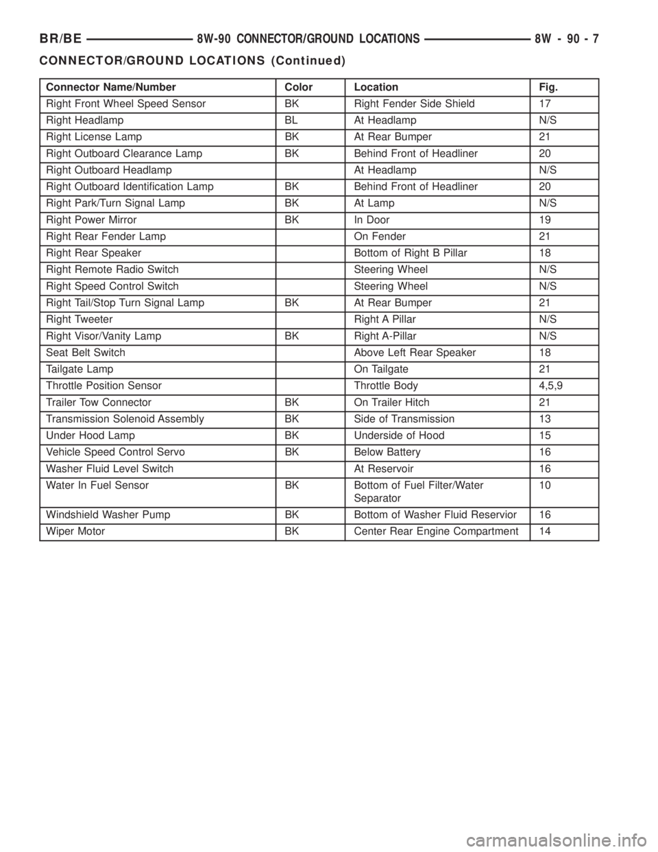
Connector Name/Number Color Location Fig.
Right Front Wheel Speed Sensor BK Right Fender Side Shield 17
Right Headlamp BL At Headlamp N/S
Right License Lamp BK At Rear Bumper 21
Right Outboard Clearance Lamp BK Behind Front of Headliner 20
Right Outboard Headlamp At Headlamp N/S
Right Outboard Identification Lamp BK Behind Front of Headliner 20
Right Park/Turn Signal Lamp BK At Lamp N/S
Right Power Mirror BK In Door 19
Right Rear Fender Lamp On Fender 21
Right Rear Speaker Bottom of Right B Pillar 18
Right Remote Radio Switch Steering Wheel N/S
Right Speed Control Switch Steering Wheel N/S
Right Tail/Stop Turn Signal Lamp BK At Rear Bumper 21
Right Tweeter Right A Pillar N/S
Right Visor/Vanity Lamp BK Right A-Pillar N/S
Seat Belt Switch Above Left Rear Speaker 18
Tailgate Lamp On Tailgate 21
Throttle Position Sensor Throttle Body 4,5,9
Trailer Tow Connector BK On Trailer Hitch 21
Transmission Solenoid Assembly BK Side of Transmission 13
Under Hood Lamp BK Underside of Hood 15
Vehicle Speed Control Servo BK Below Battery 16
Washer Fluid Level Switch At Reservoir 16
Water In Fuel Sensor BK Bottom of Fuel Filter/Water
Separator10
Windshield Washer Pump BK Bottom of Washer Fluid Reservior 16
Wiper Motor BK Center Rear Engine Compartment 14
BR/BE8W-90 CONNECTOR/GROUND LOCATIONS 8W - 90 - 7
CONNECTOR/GROUND LOCATIONS (Continued)
Page 1151 of 2889
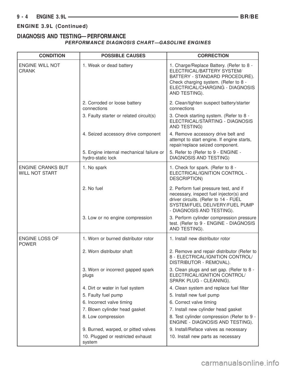
DIAGNOSIS AND TESTINGÐPERFORMANCE
PERFORMANCE DIAGNOSIS CHARTÐGASOLINE ENGINES
CONDITION POSSIBLE CAUSES CORRECTION
ENGINE WILL NOT
CRANK1. Weak or dead battery 1. Charge/Replace Battery. (Refer to 8 -
ELECTRICAL/BATTERY SYSTEM/
BATTERY - STANDARD PROCEDURE).
Check charging system. (Refer to 8 -
ELECTRICAL/CHARGING - DIAGNOSIS
AND TESTING).
2. Corroded or loose battery
connections2. Clean/tighten suspect battery/starter
connections
3. Faulty starter or related circuit(s) 3. Check starting system. (Refer to 8 -
ELECTRICAL/STARTING - DIAGNOSIS
AND TESTING)
4. Seized accessory drive component 4. Remove accessory drive belt and
attempt to start engine. If engine starts,
repair/replace seized component.
5. Engine internal mechanical failure or
hydro-static lock5. Refer to (Refer to 9 - ENGINE -
DIAGNOSIS AND TESTING)
ENGINE CRANKS BUT
WILL NOT START1. No spark 1. Check for spark. (Refer to 8 -
ELECTRICAL/IGNITION CONTROL -
DESCRIPTION)
2. No fuel 2. Perform fuel pressure test, and if
necessary, inspect fuel injector(s) and
driver circuits. (Refer to 14 - FUEL
SYSTEM/FUEL DELIVERY/FUEL PUMP
- DIAGNOSIS AND TESTING).
3. Low or no engine compression 3. Perform cylinder compression pressure
test. (Refer to 9 - ENGINE - DIAGNOSIS
AND TESTING).
ENGINE LOSS OF
POWER1. Worn or burned distributor rotor 1. Install new distributor rotor
2. Worn distributor shaft 2. Remove and repair distributor (Refer to
8 - ELECTRICAL/IGNITION CONTROL/
DISTRIBUTOR - REMOVAL).
3. Worn or incorrect gapped spark
plugs3. Clean plugs and set gap. (Refer to 8 -
ELECTRICAL/IGNITION CONTROL/
SPARK PLUG - CLEANING).
4. Dirt or water in fuel system 4. Clean system and replace fuel filter
5. Faulty fuel pump 5. Install new fuel pump
6. Incorrect valve timing 6. Correct valve timing
7. Blown cylinder head gasket 7. Install new cylinder head gasket
8. Low compression 8. Test cylinder compression (Refer to 9 -
ENGINE - DIAGNOSIS AND TESTING).
9. Burned, warped, or pitted valves 9. Install/Reface valves as necessary
10. Plugged or restricted exhaust
system10. Install new parts as necessary
9 - 4 ENGINE 3.9LBR/BE
ENGINE 3.9L (Continued)
Page 1165 of 2889
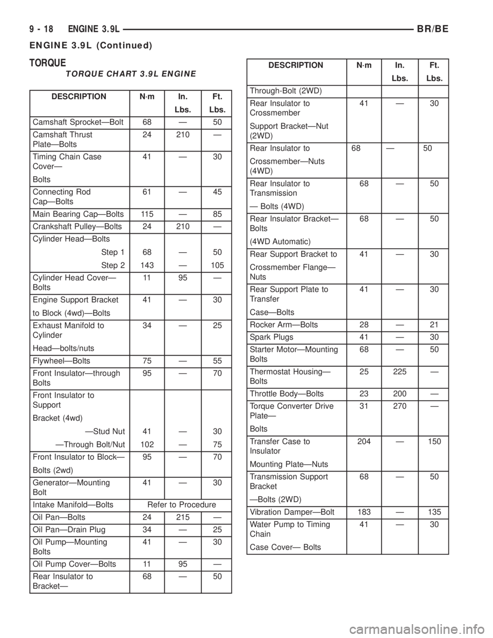
TORQUE
TORQUE CHART 3.9L ENGINE
DESCRIPTION N´m In. Ft.
Lbs. Lbs.
Camshaft SprocketÐBolt 68 Ð 50
Camshaft Thrust
PlateÐBolts24 210 Ð
Timing Chain Case
CoverÐ41 Ð 30
Bolts
Connecting Rod
CapÐBolts61 Ð 45
Main Bearing CapÐBolts 115 Ð 85
Crankshaft PulleyÐBolts 24 210 Ð
Cylinder HeadÐBolts
Step 1 68 Ð 50
Step 2 143 Ð 105
Cylinder Head CoverÐ
Bolts11 95 Ð
Engine Support Bracket 41 Ð 30
to Block (4wd)ÐBolts
Exhaust Manifold to
Cylinder34 Ð 25
HeadÐbolts/nuts
FlywheelÐBolts 75 Ð 55
Front InsulatorÐthrough
Bolts95 Ð 70
Front Insulator to
Support
Bracket (4wd)
ÐStud Nut 41 Ð 30
ÐThrough Bolt/Nut 102 Ð 75
Front Insulator to BlockÐ 95 Ð 70
Bolts (2wd)
GeneratorÐMounting
Bolt41 Ð 30
Intake ManifoldÐBolts Refer to Procedure
Oil PanÐBolts 24 215 Ð
Oil PanÐDrain Plug 34 Ð 25
Oil PumpÐMounting
Bolts41 Ð 30
Oil Pump CoverÐBolts 11 95 Ð
Rear Insulator to
BracketÐ68 Ð 50
DESCRIPTION N´m In. Ft.
Lbs. Lbs.
Through-Bolt (2WD)
Rear Insulator to
Crossmember41 Ð 30
Support BracketÐNut
(2WD)
Rear Insulator to 68 Ð 50
CrossmemberÐNuts
(4WD)
Rear Insulator to
Transmission68 Ð 50
Ð Bolts (4WD)
Rear Insulator BracketÐ
Bolts68 Ð 50
(4WD Automatic)
Rear Support Bracket to 41 Ð 30
Crossmember FlangeÐ
Nuts
Rear Support Plate to
Transfer41 Ð 30
CaseÐBolts
Rocker ArmÐBolts 28 Ð 21
Spark Plugs 41 Ð 30
Starter MotorÐMounting
Bolts68 Ð 50
Thermostat HousingÐ
Bolts25 225 Ð
Throttle BodyÐBolts 23 200 Ð
Torque Converter Drive
PlateÐ31 270 Ð
Bolts
Transfer Case to
Insulator204 Ð 150
Mounting PlateÐNuts
Transmission Support
Bracket68 Ð 50
ÐBolts (2WD)
Vibration DamperÐBolt 183 Ð 135
Water Pump to Timing
Chain41 Ð 30
Case CoverÐ Bolts
9 - 18 ENGINE 3.9LBR/BE
ENGINE 3.9L (Continued)
Page 1203 of 2889
(5) Assemble exhaust pipe to manifold and secure
with bolts, nuts and retainers. Tighten the bolts and
nuts to 34 N´m (25 ft. lbs.) torque.
(6) Lower the vehicle.
(7) Connect the negative cable to the battery.
TIMING BELT / CHAIN
COVER(S)
REMOVAL
(1) Disconnect the battery negative cable.
(2) Drain cooling system (Refer to 7 - COOLING -
STANDARD PROCEDURE).
(3) Remove the serpentine belt (Refer to 7 - COOL-
ING/ACCESSORY DRIVE/DRIVE BELTS - REMOV-
AL).
(4) Remove water pump (Refer to 7 - COOLING/
ENGINE/WATER PUMP - REMOVAL).
(5) Remove power steering pump (Refer to 19 -
STEERING/PUMP - REMOVAL).
(6) Remove vibration damper (Refer to 9 -
ENGINE/ENGINE BLOCK/VIBRATION DAMPER -
REMOVAL).
(7) Loosen oil pan bolts and remove the front bolt
at each side.
(8) Remove the cover bolts.
(9) Remove chain case cover and gasket using
extreme caution to avoid damaging oil pan gasket.
(10) From the inside of the cover tap the front
crankshaft oil seal outward. Be careful not to damage
the timing cover sealing surface.
INSTALLATION
(1) Be sure mating surfaces of chain case cover
and cylinder block are clean and free from burrs.
(2) Using a new cover gasket, carefully install
chain case cover to avoid damaging oil pan gasket.
Use a small amount of MopartGEN II Silicone Rub-
ber Adhesive Sealant, or equivalent, at the joint
between timing chain cover gasket and the oil pan
gasket. Finger tighten the timing chain cover bolts at
this time.
CAUTION: If chain cover is replaced for any reason,
be sure the oil hole (passenger side of cover) is
plugged.
NOTE: Special Tool 6635 must be used to align
cover and seal with crankshaft.
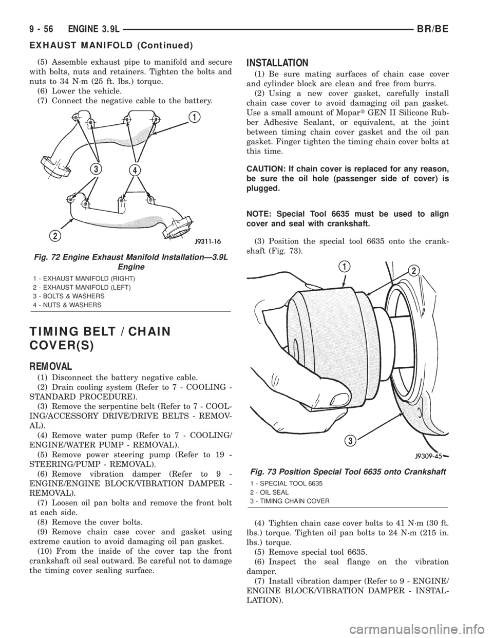
(3) Position the special tool 6635 onto the crank-
shaft (Fig. 73).
(4) Tighten chain case cover bolts to 41 N´m (30 ft.
lbs.) torque. Tighten oil pan bolts to 24 N´m (215 in.
lbs.) torque.
(5) Remove special tool 6635.
(6) Inspect the seal flange on the vibration
damper.
(7) Install vibration damper (Refer to 9 - ENGINE/
ENGINE BLOCK/VIBRATION DAMPER - INSTAL-
LATION).
Fig. 72 Engine Exhaust Manifold InstallationÐ3.9L
Engine
1 - EXHAUST MANIFOLD (RIGHT)
2 - EXHAUST MANIFOLD (LEFT)
3 - BOLTS & WASHERS
4 - NUTS & WASHERS
Fig. 73 Position Special Tool 6635 onto Crankshaft
1 - SPECIAL TOOL 6635
2 - OIL SEAL
3 - TIMING CHAIN COVER
9 - 56 ENGINE 3.9LBR/BE
EXHAUST MANIFOLD (Continued)
Page 1204 of 2889
(8) Install water pump (Refer to 7 - COOLING/EN-
GINE/WATER PUMP - INSTALLATION).
(9) Install power steering pump (Refer to 19 -
STEERING/PUMP - INSTALLATION).
(10) Install the serpentine belt (Refer to 7 - COOL-
ING/ACCESSORY DRIVE/DRIVE BELTS - INSTAL-
LATION).
(11) Install the cooling system fan (Refer to 7 -
COOLING/ENGINE/FAN DRIVE VISCOUS
CLUTCH - INSTALLATION).
(12) Position the fan shroud and install the bolts.
Tighten the bolts to 11 N´m (95 in. lbs.) torque.
(13) Fill cooling system (Refer to 7 - COOLING -
STANDARD PROCEDURE).
(14) Connect the negative cable to the battery.
TIMING BELT/CHAIN
TENSIONER
DESCRIPTION
The timing chain tensioner is a stamped steel con-
stant tension mechanical design. It is mounted to the
front of the engine, behind the timing chain drive.
OPERATION
The timing chain tension is maintained by routing
the timing chain through the tensioner assembly. A
nylon covered spring steel arm presses on the timing
chain maintaining the correct chain tension.
TIMING BELT/CHAIN AND
SPROCKETS
REMOVAL
(1) Disconnect battery negative cable.
(2) Drain cooling system (Refer to 7 - COOLING -
STANDARD PROCEDURE).
(3) Remove timing chain cover (Refer to 9 -
ENGINE/VALVE TIMING/TIMING BELT / CHAIN
COVER(S) - REMOVAL).
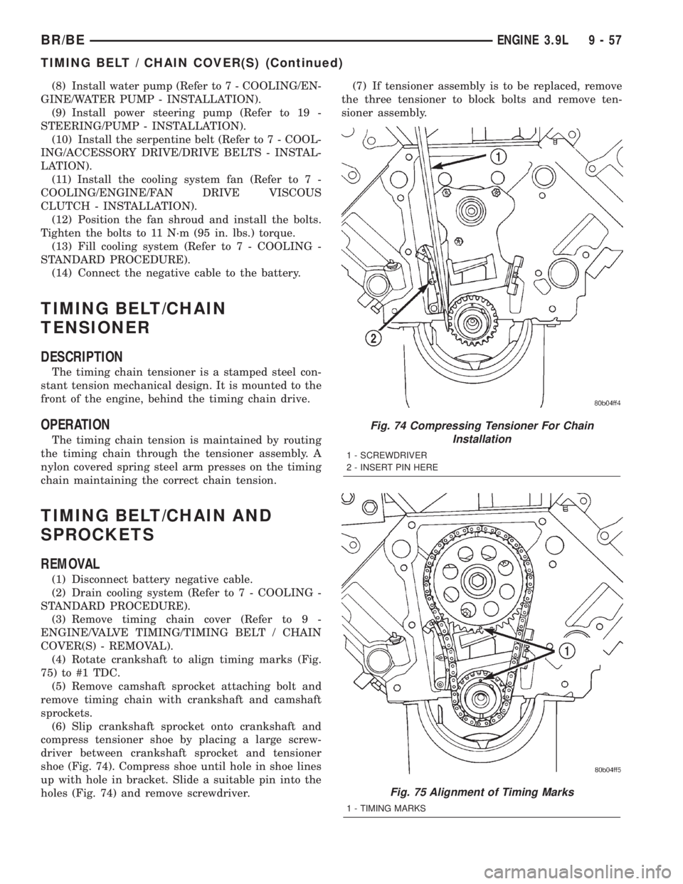
(4) Rotate crankshaft to align timing marks (Fig.
75) to #1 TDC.
(5) Remove camshaft sprocket attaching bolt and
remove timing chain with crankshaft and camshaft
sprockets.
(6) Slip crankshaft sprocket onto crankshaft and
compress tensioner shoe by placing a large screw-
driver between crankshaft sprocket and tensioner
shoe (Fig. 74). Compress shoe until hole in shoe lines
up with hole in bracket. Slide a suitable pin into the
holes (Fig. 74) and remove screwdriver.(7) If tensioner assembly is to be replaced, remove
the three tensioner to block bolts and remove ten-
sioner assembly.
Fig. 74 Compressing Tensioner For Chain
Installation
1 - SCREWDRIVER
2 - INSERT PIN HERE
Fig. 75 Alignment of Timing Marks
1 - TIMING MARKS
BR/BEENGINE 3.9L 9 - 57
TIMING BELT / CHAIN COVER(S) (Continued)
Page 1209 of 2889
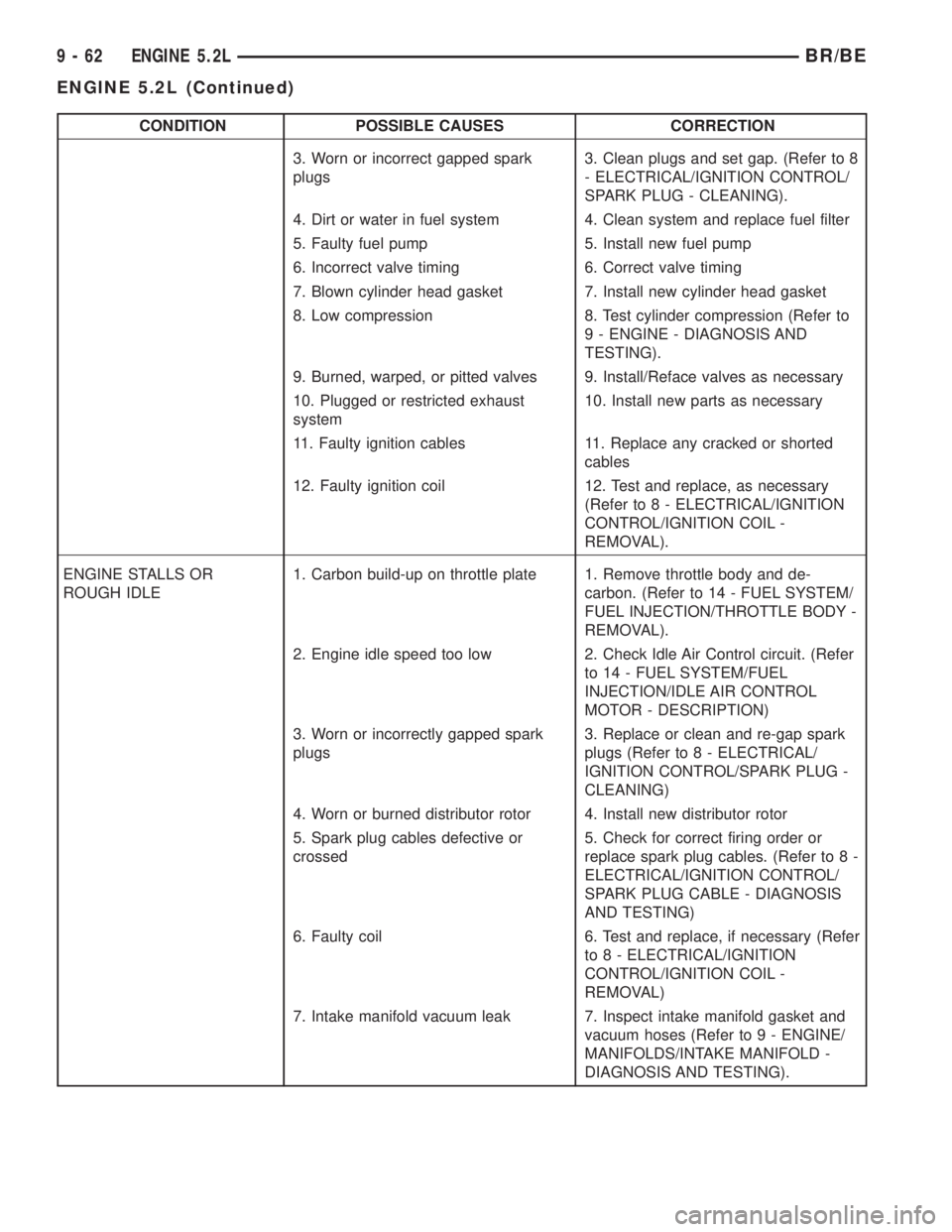
CONDITION POSSIBLE CAUSES CORRECTION
3. Worn or incorrect gapped spark
plugs3. Clean plugs and set gap. (Refer to 8
- ELECTRICAL/IGNITION CONTROL/
SPARK PLUG - CLEANING).
4. Dirt or water in fuel system 4. Clean system and replace fuel filter
5. Faulty fuel pump 5. Install new fuel pump
6. Incorrect valve timing 6. Correct valve timing
7. Blown cylinder head gasket 7. Install new cylinder head gasket
8. Low compression 8. Test cylinder compression (Refer to
9 - ENGINE - DIAGNOSIS AND
TESTING).
9. Burned, warped, or pitted valves 9. Install/Reface valves as necessary
10. Plugged or restricted exhaust
system10. Install new parts as necessary
11. Faulty ignition cables 11. Replace any cracked or shorted
cables
12. Faulty ignition coil 12. Test and replace, as necessary
(Refer to 8 - ELECTRICAL/IGNITION
CONTROL/IGNITION COIL -
REMOVAL).
ENGINE STALLS OR
ROUGH IDLE1. Carbon build-up on throttle plate 1. Remove throttle body and de-
carbon. (Refer to 14 - FUEL SYSTEM/
FUEL INJECTION/THROTTLE BODY -
REMOVAL).
2. Engine idle speed too low 2. Check Idle Air Control circuit. (Refer
to 14 - FUEL SYSTEM/FUEL
INJECTION/IDLE AIR CONTROL
MOTOR - DESCRIPTION)
3. Worn or incorrectly gapped spark
plugs3. Replace or clean and re-gap spark
plugs (Refer to 8 - ELECTRICAL/
IGNITION CONTROL/SPARK PLUG -
CLEANING)
4. Worn or burned distributor rotor 4. Install new distributor rotor
5. Spark plug cables defective or
crossed5. Check for correct firing order or
replace spark plug cables. (Refer to 8 -
ELECTRICAL/IGNITION CONTROL/
SPARK PLUG CABLE - DIAGNOSIS
AND TESTING)
6. Faulty coil 6. Test and replace, if necessary (Refer
to 8 - ELECTRICAL/IGNITION
CONTROL/IGNITION COIL -
REMOVAL)
7. Intake manifold vacuum leak 7. Inspect intake manifold gasket and
vacuum hoses (Refer to 9 - ENGINE/
MANIFOLDS/INTAKE MANIFOLD -
DIAGNOSIS AND TESTING).
9 - 62 ENGINE 5.2LBR/BE
ENGINE 5.2L (Continued)
Page 1223 of 2889
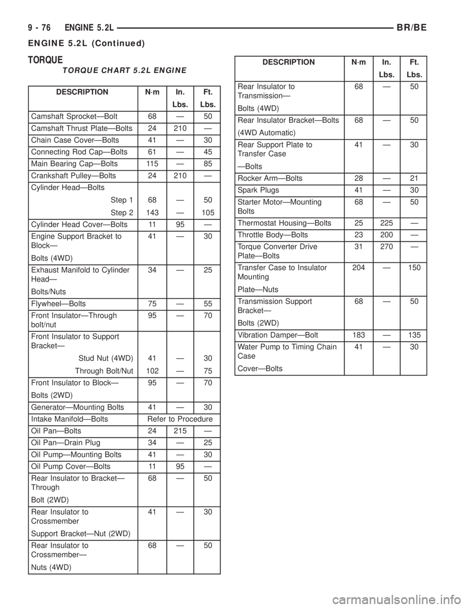
TORQUE
TORQUE CHART 5.2L ENGINE
DESCRIPTION N´m In. Ft.
Lbs. Lbs.
Camshaft SprocketÐBolt 68 Ð 50
Camshaft Thrust PlateÐBolts 24 210 Ð
Chain Case CoverÐBolts 41 Ð 30
Connecting Rod CapÐBolts 61 Ð 45
Main Bearing CapÐBolts 115 Ð 85
Crankshaft PulleyÐBolts 24 210 Ð
Cylinder HeadÐBolts
Step 1 68 Ð 50
Step 2 143 Ð 105
Cylinder Head CoverÐBolts 11 95 Ð
Engine Support Bracket to
BlockÐ41 Ð 30
Bolts (4WD)
Exhaust Manifold to Cylinder
HeadÐ34 Ð 25
Bolts/Nuts
FlywheelÐBolts 75 Ð 55
Front InsulatorÐThrough
bolt/nut95 Ð 70
Front Insulator to Support
BracketÐ
Stud Nut (4WD) 41 Ð 30
Through Bolt/Nut 102 Ð 75
Front Insulator to BlockÐ 95 Ð 70
Bolts (2WD)
GeneratorÐMounting Bolts 41 Ð 30
Intake ManifoldÐBolts Refer to Procedure
Oil PanÐBolts 24 215 Ð
Oil PanÐDrain Plug 34 Ð 25
Oil PumpÐMounting Bolts 41 Ð 30
Oil Pump CoverÐBolts 11 95 Ð
Rear Insulator to BracketÐ
Through68 Ð 50
Bolt (2WD)
Rear Insulator to
Crossmember41 Ð 30
Support BracketÐNut (2WD)
Rear Insulator to
CrossmemberÐ68 Ð 50
Nuts (4WD)
DESCRIPTION N´m In. Ft.
Lbs. Lbs.
Rear Insulator to
TransmissionÐ68 Ð 50
Bolts (4WD)
Rear Insulator BracketÐBolts 68 Ð 50
(4WD Automatic)
Rear Support Plate to
Transfer Case41 Ð 30
ÐBolts
Rocker ArmÐBolts 28 Ð 21
Spark Plugs 41 Ð 30
Starter MotorÐMounting
Bolts68 Ð 50
Thermostat HousingÐBolts 25 225 Ð
Throttle BodyÐBolts 23 200 Ð
Torque Converter Drive
PlateÐBolts31 270 Ð
Transfer Case to Insulator
Mounting204 Ð 150
PlateÐNuts
Transmission Support
BracketÐ68 Ð 50
Bolts (2WD)
Vibration DamperÐBolt 183 Ð 135
Water Pump to Timing Chain
Case41 Ð 30
CoverÐBolts
9 - 76 ENGINE 5.2LBR/BE
ENGINE 5.2L (Continued)
Page 1243 of 2889
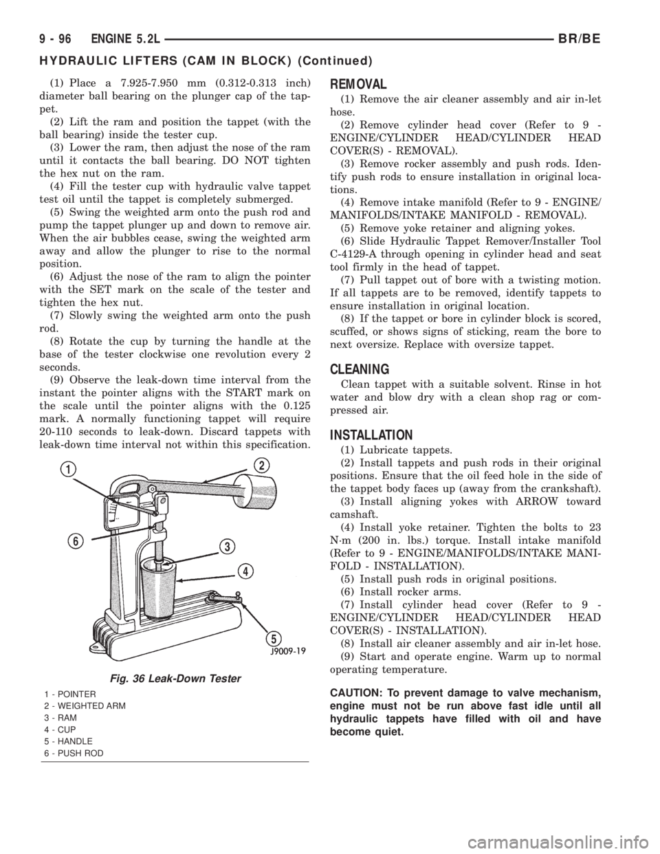
(1) Place a 7.925-7.950 mm (0.312-0.313 inch)
diameter ball bearing on the plunger cap of the tap-
pet.
(2) Lift the ram and position the tappet (with the
ball bearing) inside the tester cup.
(3) Lower the ram, then adjust the nose of the ram
until it contacts the ball bearing. DO NOT tighten
the hex nut on the ram.
(4) Fill the tester cup with hydraulic valve tappet
test oil until the tappet is completely submerged.
(5) Swing the weighted arm onto the push rod and
pump the tappet plunger up and down to remove air.
When the air bubbles cease, swing the weighted arm
away and allow the plunger to rise to the normal
position.
(6) Adjust the nose of the ram to align the pointer
with the SET mark on the scale of the tester and
tighten the hex nut.
(7) Slowly swing the weighted arm onto the push
rod.
(8) Rotate the cup by turning the handle at the
base of the tester clockwise one revolution every 2
seconds.
(9) Observe the leak-down time interval from the
instant the pointer aligns with the START mark on
the scale until the pointer aligns with the 0.125
mark. A normally functioning tappet will require
20-110 seconds to leak-down. Discard tappets with
leak-down time interval not within this specification.REMOVAL
(1) Remove the air cleaner assembly and air in-let
hose.
(2) Remove cylinder head cover (Refer to 9 -
ENGINE/CYLINDER HEAD/CYLINDER HEAD
COVER(S) - REMOVAL).
(3) Remove rocker assembly and push rods. Iden-
tify push rods to ensure installation in original loca-
tions.
(4) Remove intake manifold (Refer to 9 - ENGINE/
MANIFOLDS/INTAKE MANIFOLD - REMOVAL).
(5) Remove yoke retainer and aligning yokes.
(6) Slide Hydraulic Tappet Remover/Installer Tool
C-4129-A through opening in cylinder head and seat
tool firmly in the head of tappet.
(7) Pull tappet out of bore with a twisting motion.
If all tappets are to be removed, identify tappets to
ensure installation in original location.
(8) If the tappet or bore in cylinder block is scored,
scuffed, or shows signs of sticking, ream the bore to
next oversize. Replace with oversize tappet.
CLEANING
Clean tappet with a suitable solvent. Rinse in hot
water and blow dry with a clean shop rag or com-
pressed air.
INSTALLATION
(1) Lubricate tappets.
(2) Install tappets and push rods in their original
positions. Ensure that the oil feed hole in the side of
the tappet body faces up (away from the crankshaft).
(3) Install aligning yokes with ARROW toward
camshaft.
(4) Install yoke retainer. Tighten the bolts to 23
N´m (200 in. lbs.) torque. Install intake manifold
(Refer to 9 - ENGINE/MANIFOLDS/INTAKE MANI-
FOLD - INSTALLATION).
(5) Install push rods in original positions.
(6) Install rocker arms.
(7) Install cylinder head cover (Refer to 9 -
ENGINE/CYLINDER HEAD/CYLINDER HEAD
COVER(S) - INSTALLATION).
(8) Install air cleaner assembly and air in-let hose.
(9) Start and operate engine. Warm up to normal
operating temperature.
CAUTION: To prevent damage to valve mechanism,
engine must not be run above fast idle until all
hydraulic tappets have filled with oil and have
become quiet.
Fig. 36 Leak-Down Tester
1 - POINTER
2 - WEIGHTED ARM
3 - RAM
4 - CUP
5 - HANDLE
6 - PUSH ROD
9 - 96 ENGINE 5.2LBR/BE
HYDRAULIC LIFTERS (CAM IN BLOCK) (Continued)