water pump DODGE RAM 2001 Service Workshop Manual
[x] Cancel search | Manufacturer: DODGE, Model Year: 2001, Model line: RAM, Model: DODGE RAM 2001Pages: 2889, PDF Size: 68.07 MB
Page 415 of 2889
WARNING: WEAR PROTECTIVE EYEWEAR THAT
MEETS THE REQUIREMENTS OF OSHA AND ANSI
Z87.1±1968. WEAR STANDARD INDUSTRIAL RUB-
BER GLOVES.
KEEP LIGHTED CIGARETTES, SPARKS, FLAMES,
AND OTHER IGNITION SOURCES AWAY FROM THE
AREA TO PREVENT THE IGNITION OF COMBUSTI-
BLE LIQUIDS AND GASES. KEEP A CLASS (B) FIRE
EXTINGUISHER IN THE AREA WHERE THE
FLUSHER WILL BE USED.
KEEP THE AREA WELL VENTILATED.
DO NOT LET FLUSHING SOLVENT COME IN CON-
TACT WITH YOUR EYES OR SKIN: IF EYE CONTAM-
INATION OCCURS, FLUSH EYES WITH WATER FOR
15 TO 20 SECONDS. REMOVE CONTAMINATED
CLOTHING AND WASH AFFECTED SKIN WITH
SOAP AND WATER. SEEK MEDICAL ATTENTION.
(1) Remove cover plate filler plug on Tool 6906-B.
Fill reservoir 1/2 to 3/4 full of fresh flushing solution.
Flushing solvents are petroleum based solutions gen-
erally used to clean automatic transmission compo-
nents.DO NOTuse solvents containing acids, water,
gasoline, or any other corrosive liquids.
(2) Reinstall filler plug on Tool 6906-B.(3) Verify pump power switch is turned OFF. Con-
nect red alligator clip to positive (+) battery post.
Connect black (-) alligator clip to a good ground.
(4) Disconnect the cooler lines at the transmission.
NOTE: When flushing transmission cooler and
lines, ALWAYS reverse flush.
NOTE: The converter drainback valve must be
removed and an appropriate replacement hose
installed to bridge the space between the transmis-
sion cooler line and the cooler fitting. Failure to
remove the drainback valve will prevent reverse
flushing the system. A suitable replacement hose
can be found in the adapter kit supplied with the
flushing tool.
(5) Connect the BLUE pressure line to the OUT-
LET (From) cooler line.
(6) Connect the CLEAR return line to the INLET
(To) cooler line
(7) Turn pump ON for two to three minutes to
flush cooler(s) and lines.
(8) Turn pump OFF.
(9) Disconnect CLEAR suction line from reservoir
at cover plate. Disconnect CLEAR return line at
cover plate, and place it in a drain pan.
(10) Turn pump ON for 30 seconds to purge flush-
ing solution from cooler and lines. Turn pump OFF.
(11) Place CLEAR suction line into a one quart
container of MopartATF +4, type 9602, Automatic
Transmission Fluid.
(12) Turn pump ON until all transmission fluid is
removed from the one quart container and lines. This
purges any residual cleaning solvent from the trans-
mission cooler and lines. Turn pump OFF.
(13) Disconnect alligator clips from battery. Recon-
nect flusher lines to cover plate, and remove flushing
adapters from cooler lines.
STANDARD PROCEDURE - FLUSHING COOLER
AND TUBES - WITHOUT RADIATOR IN-TANK
TRANSMISSION OIL COOLER
When a transmission failure has contaminated the
fluid, the oil cooler(s) must be flushed. The torque
converter must also be replaced. This will insure that
metal particles or sludged oil are not later trans-
ferred back into the reconditioned (or replaced) trans-
mission.
(1) Remove cover plate filler plug on Tool 6906B.
Fill reservoir 1/2 to 3/4 full of fresh flushing solution.
Flushing solvents are petroleum based solutions gen-
erally used to clean automatic transmission compo-
nents.DO NOTuse solvents containing acids, water,
gasoline, or any other corrosive liquids.
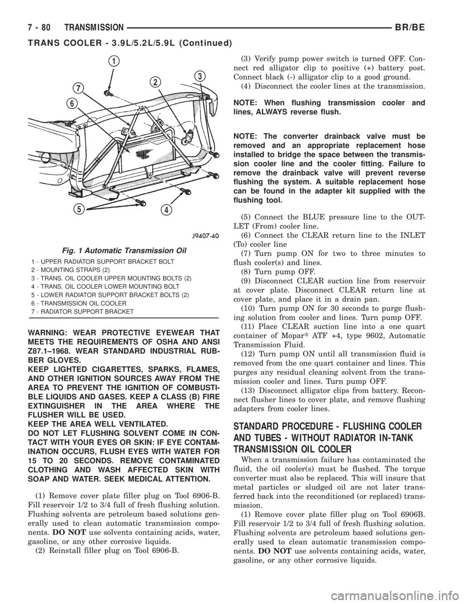
Fig. 1 Automatic Transmission Oil
1 - UPPER RADIATOR SUPPORT BRACKET BOLT
2 - MOUNTING STRAPS (2)
3 - TRANS. OIL COOLER UPPER MOUNTING BOLTS (2)
4 - TRANS. OIL COOLER LOWER MOUNTING BOLT
5 - LOWER RADIATOR SUPPORT BRACKET BOLTS (2)
6 - TRANSMISSION OIL COOLER
7 - RADIATOR SUPPORT BRACKET
7 - 80 TRANSMISSIONBR/BE
TRANS COOLER - 3.9L/5.2L/5.9L (Continued)
Page 418 of 2889
STANDARD PROCEDURE - FLUSHING
COOLERS AND TUBES - WITH RADIATOR
IN-TANK TRANSMISSION OIL COOLER
When a transmission failure has contaminated the
fluid, the oil cooler(s) must be flushed. The torque
converter must also be replaced. This will insure that
metal particles or sludged oil are not later trans-
ferred back into the reconditioned (or replaced) trans-
mission.
The only recommended procedure for flushing cool-
ers and lines is to use Tool 6906-B Cooler Flusher.
WARNING: WEAR PROTECTIVE EYEWEAR THAT
MEETS THE REQUIREMENTS OF OSHA AND ANSI
Z87.1±1968. WEAR STANDARD INDUSTRIAL RUB-
BER GLOVES.
KEEP LIGHTED CIGARETTES, SPARKS, FLAMES,
AND OTHER IGNITION SOURCES AWAY FROM THE
AREA TO PREVENT THE IGNITION OF COMBUSTI-
BLE LIQUIDS AND GASES. KEEP A CLASS (B) FIRE
EXTINGUISHER IN THE AREA WHERE THE
FLUSHER WILL BE USED.
KEEP THE AREA WELL VENTILATED.
DO NOT LET FLUSHING SOLVENT COME IN CON-
TACT WITH YOUR EYES OR SKIN: IF EYE CONTAM-
INATION OCCURS, FLUSH EYES WITH WATER FOR
15 TO 20 SECONDS. REMOVE CONTAMINATED
CLOTHING AND WASH AFFECTED SKIN WITH
SOAP AND WATER. SEEK MEDICAL ATTENTION.
(1) Remove cover plate filler plug on Tool 6906-B.
Fill reservoir 1/2 to 3/4 full of fresh flushing solution.
Flushing solvents are petroleum based solutions gen-
erally used to clean automatic transmission compo-
nents.DO NOTuse solvents containing acids, water,
gasoline, or any other corrosive liquids.(2) Reinstall filler plug on Tool 6906-B.
(3) Verify pump power switch is turned OFF. Con-
nect red alligator clip to positive (+) battery post.
Connect black (-) alligator clip to a good ground.
(4) Disconnect the cooler lines at the transmission.
NOTE: When flushing transmission cooler and
lines, ALWAYS reverse flush.
NOTE: The converter drainback valve must be
removed and an appropriate replacement hose
installed to bridge the space between the transmis-
sion cooler line and the cooler fitting. Failure to
remove the drainback valve will prevent reverse
flushing the system. A suitable replacement hose
can be found in the adapter kit supplied with the
flushing tool.
(5) Connect the BLUE pressure line to the OUT-
LET (From) cooler line.
(6) Connect the CLEAR return line to the INLET
(To) cooler line
(7) Turn pump ON for two to three minutes to
flush cooler(s) and lines.
(8) Turn pump OFF.
(9) Disconnect CLEAR suction line from reservoir
at cover plate. Disconnect CLEAR return line at
cover plate, and place it in a drain pan.
(10) Turn pump ON for 30 seconds to purge flush-
ing solution from cooler and lines. Turn pump OFF.
(11) Place CLEAR suction line into a one quart
container of MopartATF +4, type 9602, Automatic
Transmission Fluid.
(12) Turn pump ON until all transmission fluid is
removed from the one quart container and lines. This
purges any residual cleaning solvent from the trans-
mission cooler and lines. Turn pump OFF.
(13) Disconnect alligator clips from battery. Recon-
nect flusher lines to cover plate, and remove flushing
adapters from cooler lines.
STANDARD PROCEDURE - FLUSHING COOLER
AND TUBES - WITHOUT RADIATOR IN-TANK
TRANSMISSION OIL COOLER
When a transmission failure has contaminated the
fluid, the oil cooler(s) must be flushed. The torque
converter must also be replaced. This will insure that
metal particles or sludged oil are not later trans-
ferred back into the reconditioned (or replaced) trans-
mission.
(1) Remove cover plate filler plug on Tool 6906B.
Fill reservoir 1/2 to 3/4 full of fresh flushing solution.
Flushing solvents are petroleum based solutions gen-
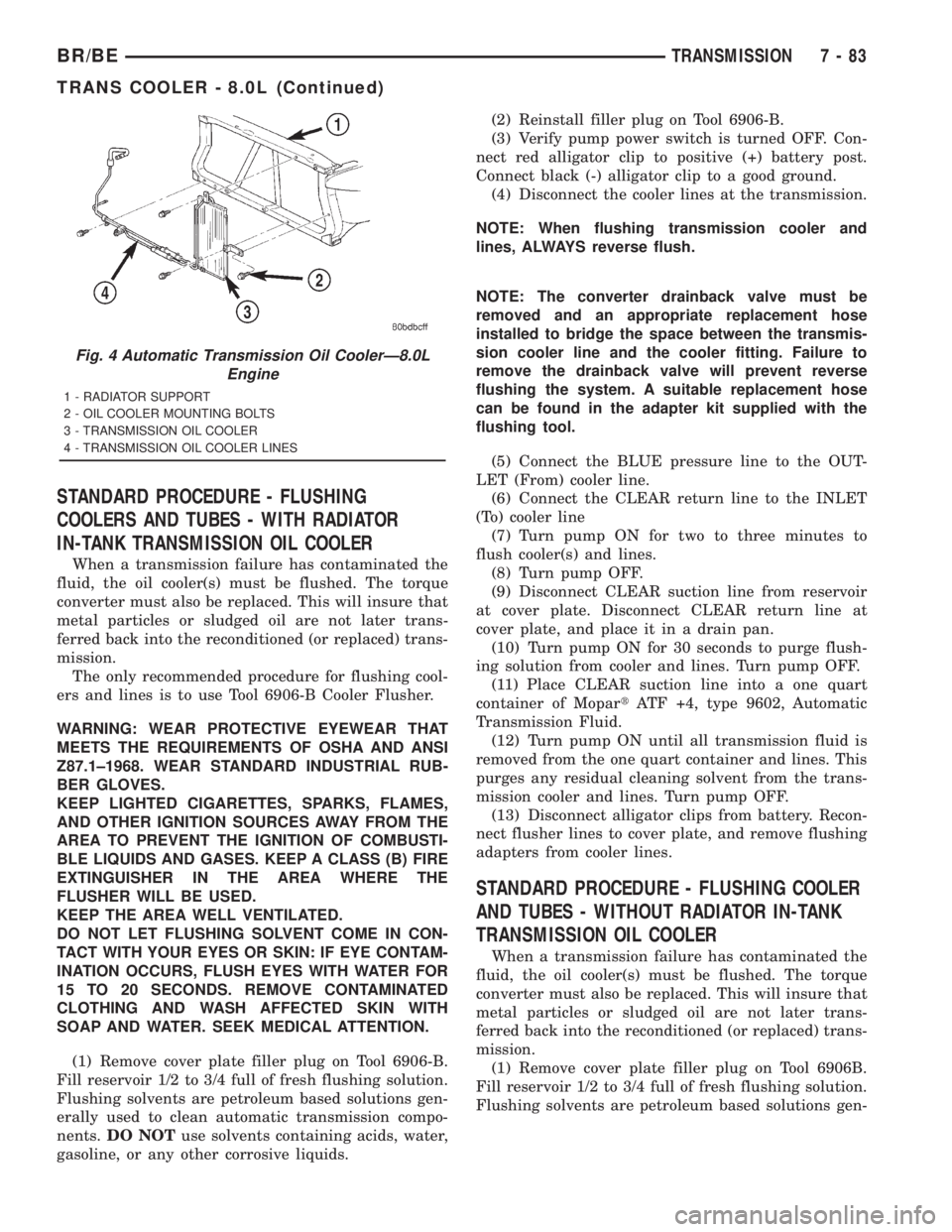
Fig. 4 Automatic Transmission Oil CoolerÐ8.0L
Engine
1 - RADIATOR SUPPORT
2 - OIL COOLER MOUNTING BOLTS
3 - TRANSMISSION OIL COOLER
4 - TRANSMISSION OIL COOLER LINES
BR/BETRANSMISSION 7 - 83
TRANS COOLER - 8.0L (Continued)
Page 419 of 2889
erally used to clean automatic transmission compo-
nents.DO NOTuse solvents containing acids, water,
gasoline, or any other corrosive liquids.
(2) Reinstall filler plug on Tool 6906B.
(3) Verify pump power switch is turned OFF. Con-
nect red alligator clip to positive (+) battery post.
Connect black (-) alligator clip to a good ground.
(4) Disconnect the cooler lines at the transmission.
NOTE: When flushing transmission cooler and
lines, ALWAYS reverse flush.
NOTE: The converter drainback valve must be
removed and an appropriate replacement hose
installed to bridge the space between the transmis-
sion cooler line and the cooler fitting. Failure to
remove the drainback valve will prevent reverse
flushing the system. A suitable replacement hose
can be found in the adapter kit supplied with the
flushing tool.
(5) Connect the BLUE pressure line to the OUT-
LET (From) cooler line.
(6) Connect the CLEAR return line to the INLET
(To) cooler line
(7) Remove the transmission oil cooler from the
vehicle. (Refer to 7 - COOLING/TRANSMISSION/
TRANS COOLER - REMOVAL)
(8) Remove the transmission oil cooler thermostat.
(Refer to 7 - COOLING/TRANSMISSION/TRANS
COOLER - DISASSEMBLY)
(9) Re-install the thermostat cover onto the oil
cooler and install the snap-ring.
(10) Re-connect the oil cooler to the transmission
cooler lines.
(11) Turn pump ON for two to three minutes to
flush cooler(s) and lines.
NOTE: This flushes the bypass circuit of the cooler
only.
(12) Turn pump OFF.
(13) Remove the thermostat cover from the oil
cooler.
(14) Install Special Tool Cooler Plug 8414 into the
transmission oil cooler.
(15) Re-install the thermostat cover onto the oil
cooler and install the snap-ring.
(16) Turn pump ON for two to three minutes to
flush cooler(s) and lines.
NOTE: This flushes the main oil cooler core pas-
sages only.
(17) Turn pump OFF.
(18) Remove the thermostat cover from the oil
cooler.(19) Remove Special Tool Cooler Plug 8414 from
the transmission oil cooler.
(20) Install a new thermostat spring, thermostat,
cover, and snap-ring into the transmission oil cooler.
(Refer to 7 - COOLING/TRANSMISSION/TRANS
COOLER - ASSEMBLY)
(21) Install the transmission oil cooler onto the
vehicle. (Refer to 7 - COOLING/TRANSMISSION/
TRANS COOLER - INSTALLATION)
(22) Disconnect CLEAR suction line from reservoir
at cover plate. Disconnect CLEAR return line at
cover plate, and place it in a drain pan.
(23) Turn pump ON for 30 seconds to purge flush-
ing solution from cooler and lines. Turn pump OFF.
(24) Place CLEAR suction line into a one quart
container of MopartATF +4, type 9602, Automatic
Transmission fluid.
(25) Turn pump ON until all transmission fluid is
removed from the one quart container and lines. This
purges any residual cleaning solvent from the trans-
mission cooler and lines. Turn pump OFF.
(26) Disconnect alligator clips from battery. Recon-
nect flusher lines to cover plate, and remove flushing
adapters from cooler lines.
REMOVAL
(1) Place a drain pan under the oil cooler lines.
(2) Disconnect the two transmission lines from the
oil cooler by loosening the two worm gear clamps and
pulling the rubber hoses off of the oil cooler tubes
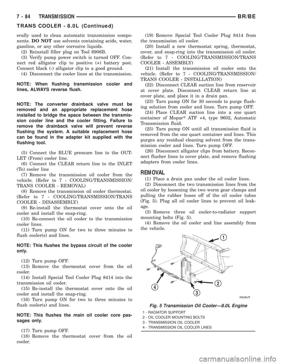
(Fig. 5). Plug all oil cooler lines to prevent oil leak-
age.
(3) Remove three oil cooler-to-radiator support
mounting bolts (Fig. 5).
(4) Remove the oil cooler and line assembly from
the vehicle.
Fig. 5 Transmission Oil CoolerÐ8.0L Engine
1 - RADIATOR SUPPORT
2 - OIL COOLER MOUNTING BOLTS
3 - TRANSMISSION OIL COOLER
4 - TRANSMISSION OIL COOLER LINES
7 - 84 TRANSMISSIONBR/BE
TRANS COOLER - 8.0L (Continued)
Page 421 of 2889
WARNING: WEAR PROTECTIVE EYEWEAR THAT
MEETS THE REQUIREMENTS OF OSHA AND ANSI
Z87.1±1968. WEAR STANDARD INDUSTRIAL RUB-
BER GLOVES.
KEEP LIGHTED CIGARETTES, SPARKS, FLAMES,
AND OTHER IGNITION SOURCES AWAY FROM THE
AREA TO PREVENT THE IGNITION OF COMBUSTI-
BLE LIQUIDS AND GASES. KEEP A CLASS (B) FIRE
EXTINGUISHER IN THE AREA WHERE THE
FLUSHER WILL BE USED.
KEEP THE AREA WELL VENTILATED.
DO NOT LET FLUSHING SOLVENT COME IN CON-
TACT WITH YOUR EYES OR SKIN: IF EYE CONTAM-
INATION OCCURS, FLUSH EYES WITH WATER FOR
15 TO 20 SECONDS. REMOVE CONTAMINATED
CLOTHING AND WASH AFFECTED SKIN WITH
SOAP AND WATER. SEEK MEDICAL ATTENTION.
(1) Remove cover plate filler plug on Tool 6906-B.
Fill reservoir 1/2 to 3/4 full of fresh flushing solution.
Flushing solvents are petroleum based solutions gen-
erally used to clean automatic transmission compo-
nents.DO NOTuse solvents containing acids, water,
gasoline, or any other corrosive liquids.
(2) Reinstall filler plug on Tool 6906-B.
(3) Verify pump power switch is turned OFF. Con-
nect red alligator clip to positive (+) battery post.
Connect black (-) alligator clip to a good ground.
(4) Disconnect the cooler lines at the transmission.
NOTE: When flushing transmission cooler and
lines, ALWAYS reverse flush.
NOTE: The converter drainback valve must be
removed and an appropriate replacement hose
installed to bridge the space between the transmis-
sion cooler line and the cooler fitting. Failure to
remove the drainback valve will prevent reverse
flushing the system. A suitable replacement hose
can be found in the adapter kit supplied with the
flushing tool.
(5) Connect the BLUE pressure line to the OUT-
LET (From) cooler line.
(6) Connect the CLEAR return line to the INLET
(To) cooler line
(7) Turn pump ON for two to three minutes to
flush cooler(s) and lines.
(8) Turn pump OFF.
(9) Disconnect CLEAR suction line from reservoir
at cover plate. Disconnect CLEAR return line at
cover plate, and place it in a drain pan.
(10) Turn pump ON for 30 seconds to purge flush-
ing solution from cooler and lines. Turn pump OFF.(11) Place CLEAR suction line into a one quart
container of MopartATF +4, type 9602, Automatic
Transmission Fluid.
(12) Turn pump ON until all transmission fluid is
removed from the one quart container and lines. This
purges any residual cleaning solvent from the trans-
mission cooler and lines. Turn pump OFF.
(13) Disconnect alligator clips from battery. Recon-
nect flusher lines to cover plate, and remove flushing
adapters from cooler lines.
STANDARD PROCEDURE - FLUSHING COOLER
AND TUBES - WITHOUT RADIATOR IN-TANK
TRANSMISSION OIL COOLER
When a transmission failure has contaminated the
fluid, the oil cooler(s) must be flushed. The torque
converter must also be replaced. This will insure that
metal particles or sludged oil are not later trans-
ferred back into the reconditioned (or replaced) trans-
mission.
(1) Remove cover plate filler plug on Tool 6906B.
Fill reservoir 1/2 to 3/4 full of fresh flushing solution.
Flushing solvents are petroleum based solutions gen-
erally used to clean automatic transmission compo-
nents.DO NOTuse solvents containing acids, water,
gasoline, or any other corrosive liquids.
(2) Reinstall filler plug on Tool 6906B.
(3) Verify pump power switch is turned OFF. Con-
nect red alligator clip to positive (+) battery post.
Connect black (-) alligator clip to a good ground.
(4) Disconnect the cooler lines at the transmission.
NOTE: When flushing transmission cooler and
lines, ALWAYS reverse flush.
NOTE: The converter drainback valve must be
removed and an appropriate replacement hose
installed to bridge the space between the transmis-
sion cooler line and the cooler fitting. Failure to
remove the drainback valve will prevent reverse
flushing the system. A suitable replacement hose
can be found in the adapter kit supplied with the
flushing tool.
(5) Connect the BLUE pressure line to the OUT-
LET (From) cooler line.
(6) Connect the CLEAR return line to the INLET
(To) cooler line
(7) Remove the transmission oil cooler from the
vehicle. (Refer to 7 - COOLING/TRANSMISSION/
TRANS COOLER - REMOVAL)
(8) Remove the transmission oil cooler thermostat.
(Refer to 7 - COOLING/TRANSMISSION/TRANS
COOLER - DISASSEMBLY)
7 - 86 TRANSMISSIONBR/BE
TRANS COOLER - 5.9L DIESEL (Continued)
Page 422 of 2889
(9) Re-install the thermostat cover onto the oil
cooler and install the snap-ring.
(10) Re-connect the oil cooler to the transmission
cooler lines.
(11) Turn pump ON for two to three minutes to
flush cooler(s) and lines.
NOTE: This flushes the bypass circuit of the cooler
only.
(12) Turn pump OFF.
(13) Remove the thermostat cover from the oil
cooler.
(14) Install Special Tool Cooler Plug 8414 into the
transmission oil cooler.
(15) Re-install the thermostat cover onto the oil
cooler and install the snap-ring.
(16) Turn pump ON for two to three minutes to
flush cooler(s) and lines.
NOTE: This flushes the main oil cooler core pas-
sages only.
(17) Turn pump OFF.
(18) Remove the thermostat cover from the oil
cooler.
(19) Remove Special Tool Cooler Plug 8414 from
the transmission oil cooler.
(20) Install a new thermostat spring, thermostat,
cover, and snap-ring into the transmission oil cooler.
(Refer to 7 - COOLING/TRANSMISSION/TRANS
COOLER - ASSEMBLY)
(21) Install the transmission oil cooler onto the
vehicle. (Refer to 7 - COOLING/TRANSMISSION/
TRANS COOLER - INSTALLATION)
(22) Disconnect CLEAR suction line from reservoir
at cover plate. Disconnect CLEAR return line at
cover plate, and place it in a drain pan.
(23) Turn pump ON for 30 seconds to purge flush-
ing solution from cooler and lines. Turn pump OFF.
(24) Place CLEAR suction line into a one quart
container of MopartATF +4, type 9602, Automatic
Transmission fluid.
(25) Turn pump ON until all transmission fluid is
removed from the one quart container and lines. This
purges any residual cleaning solvent from the trans-
mission cooler and lines. Turn pump OFF.
(26) Disconnect alligator clips from battery. Recon-
nect flusher lines to cover plate, and remove flushing
adapters from cooler lines.
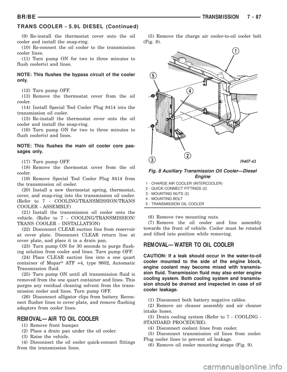
REMOVALÐAIR TO OIL COOLER
(1) Remove front bumper.
(2) Place a drain pan under the oil cooler.
(3) Raise the vehicle.
(4) Disconnect the oil cooler quick-connect fittings
from the transmission lines.(5) Remove the charge air cooler-to-oil cooler bolt
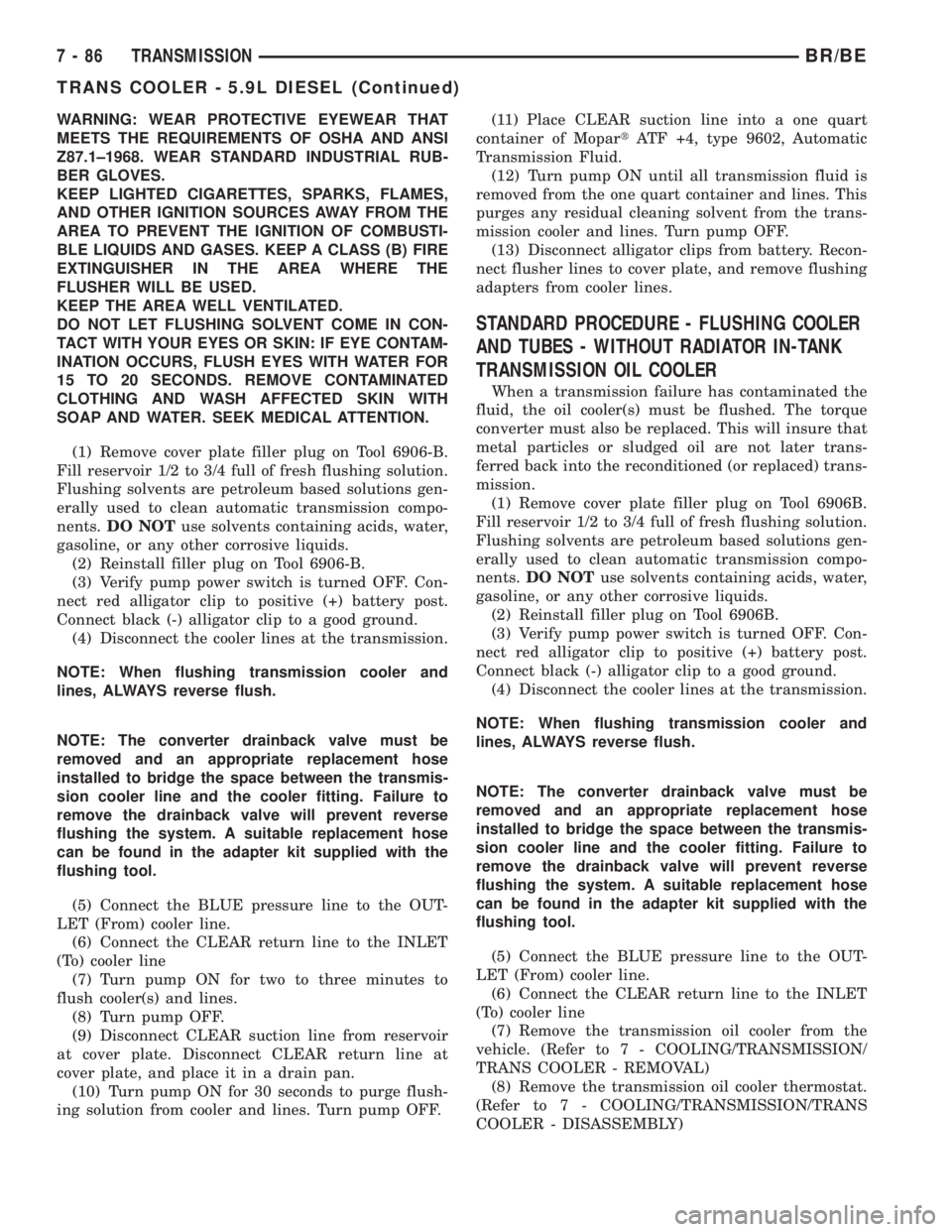
(Fig. 8).
(6) Remove two mounting nuts.
(7) Remove the oil cooler and line assembly
towards the front of vehicle. Cooler must be rotated
and tilted into position while removing.
REMOVALÐWATER TO OIL COOLER
CAUTION: If a leak should occur in the water-to-oil
cooler mounted to the side of the engine block,
engine coolant may become mixed with transmis-
sion fluid. Transmission fluid may also enter engine
cooling system. Both cooling system and transmis-
sion should be drained and inspected in case of oil
cooler leakage.
(1) Disconnect both battery negative cables.
(2) Remove air cleaner assembly and air cleaner
intake hoses.
(3) Drain cooling system (Refer to 7 - COOLING -
STANDARD PROCEDURE).
(4) Disconnect coolant lines from cooler.
(5) Disconnect transmission oil lines from cooler.
Plug cooler lines to prevent oil leakage.
(6) Remove oil cooler mounting straps (Fig. 9).
Fig. 8 Auxiliary Transmission Oil CoolerÐDiesel
Engine
1 - CHARGE AIR COOLER (INTERCOOLER)
2 - QUICK-CONNECT FITTINGS (2)
3 - MOUNTING NUTS (2)
4 - MOUNTING BOLT
5 - TRANSMISSION OIL COOLER
BR/BETRANSMISSION 7 - 87
TRANS COOLER - 5.9L DIESEL (Continued)
Page 464 of 2889
ENGINE CONTROL MODULE
DESCRIPTION - ECM
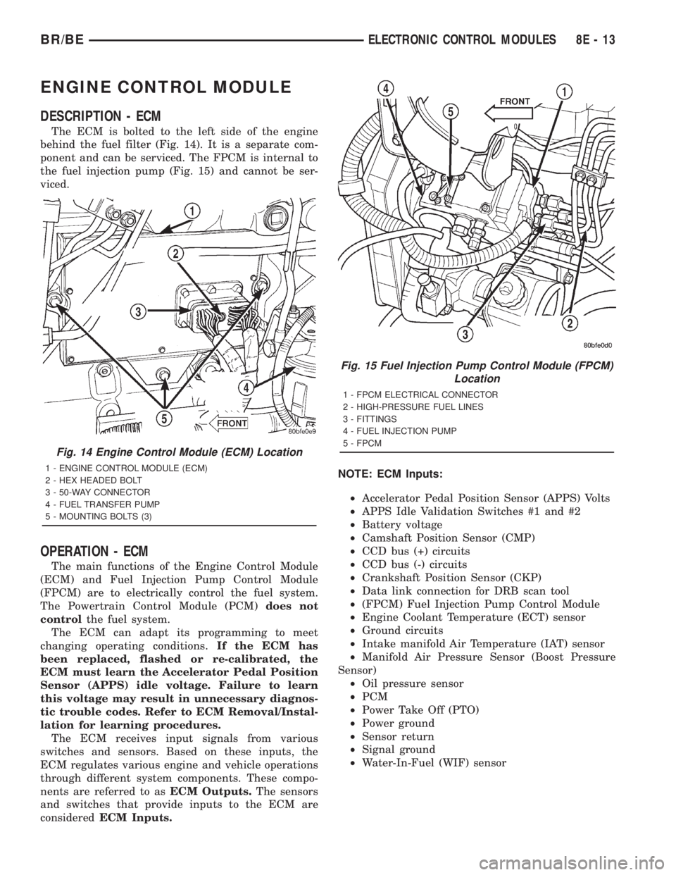
The ECM is bolted to the left side of the engine
behind the fuel filter (Fig. 14). It is a separate com-
ponent and can be serviced. The FPCM is internal to
the fuel injection pump (Fig. 15) and cannot be ser-
viced.
OPERATION - ECM
The main functions of the Engine Control Module
(ECM) and Fuel Injection Pump Control Module
(FPCM) are to electrically control the fuel system.
The Powertrain Control Module (PCM)does not
controlthe fuel system.
The ECM can adapt its programming to meet
changing operating conditions.If the ECM has
been replaced, flashed or re-calibrated, the
ECM must learn the Accelerator Pedal Position
Sensor (APPS) idle voltage. Failure to learn
this voltage may result in unnecessary diagnos-
tic trouble codes. Refer to ECM Removal/Instal-
lation for learning procedures.
The ECM receives input signals from various
switches and sensors. Based on these inputs, the
ECM regulates various engine and vehicle operations
through different system components. These compo-
nents are referred to asECM Outputs.The sensors
and switches that provide inputs to the ECM are
consideredECM Inputs.NOTE: ECM Inputs:
²Accelerator Pedal Position Sensor (APPS) Volts
²APPS Idle Validation Switches #1 and #2
²Battery voltage
²Camshaft Position Sensor (CMP)
²CCD bus (+) circuits
²CCD bus (-) circuits
²Crankshaft Position Sensor (CKP)
²Data link connection for DRB scan tool
²(FPCM) Fuel Injection Pump Control Module
²Engine Coolant Temperature (ECT) sensor
²Ground circuits
²Intake manifold Air Temperature (IAT) sensor
²Manifold Air Pressure Sensor (Boost Pressure
Sensor)
²Oil pressure sensor
²PCM
²Power Take Off (PTO)
²Power ground
²Sensor return
²Signal ground
²Water-In-Fuel (WIF) sensor
Fig. 14 Engine Control Module (ECM) Location
1 - ENGINE CONTROL MODULE (ECM)
2 - HEX HEADED BOLT
3 - 50-WAY CONNECTOR
4 - FUEL TRANSFER PUMP
5 - MOUNTING BOLTS (3)
Fig. 15 Fuel Injection Pump Control Module (FPCM)
Location
1 - FPCM ELECTRICAL CONNECTOR
2 - HIGH-PRESSURE FUEL LINES
3 - FITTINGS
4 - FUEL INJECTION PUMP
5 - FPCM
BR/BEELECTRONIC CONTROL MODULES 8E - 13
Page 465 of 2889
NOTE: ECM Outputs:
After inputs are received by the ECM, certain sen-
sors, switches and components are controlled or reg-
ulated by the ECM. These are consideredECM
Outputs.These outputs are for:
²CCD bus (+) circuits
²CCD bus (-) circuits
²CKP and APPS outputs to the PCM
²Data link connection for DRB scan tool
²Five volt sensor supply
²Fuel injection pump
²Fuel injection pump relay
²(FPCM) Fuel Pump Control Module
²Fuel transfer (lift) pump
²Intake manifold air heater relays #1 and #2 con-
trol circuits
²Malfunction indicator lamp (Check engine lamp)
²Oil pressure gauge/warning lamp
²PCM
²Wait-to-start warning lamp
²Water-In-Fuel (WIF) warning lamp
REMOVAL
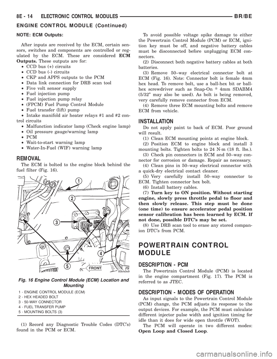
The ECM is bolted to the engine block behind the
fuel filter (Fig. 16).
(1) Record any Diagnostic Trouble Codes (DTC's)
found in the PCM or ECM.To avoid possible voltage spike damage to either
the Powertrain Control Module (PCM) or ECM, igni-
tion key must be off, and negative battery cables
must be disconnected before unplugging ECM con-
nectors.
(2) Disconnect both negative battery cables at both
batteries.
(3) Remove 50±way electrical connector bolt at
ECM (Fig. 16). Note: Connector bolt is female 4mm
hex head. To remove bolt, use a ball-hex bit or ball-
hex screwdriver such as Snap-Ont4mm SDABM4
(5/32º may also be used). As bolt is being removed,
very carefully remove connector from ECM.
(4) Remove three ECM mounting bolts and remove
ECM from vehicle.
INSTALLATION
Do not apply paint to back of ECM. Poor ground
will result.
(1) Clean ECM mounting points at engine block.
(2) Position ECM to engine block and install 3
mounting bolts. Tighten bolts to 24 N´m (18 ft. lbs.).
(3) Check pin connectors in ECM and 50±way con-
nector for corrosion or damage. Repair as necessary.
(4) Clean pins in 50±way electrical connector with
a quick-dry electrical contact cleaner.
(5) Very carefully install 50±way connector to
ECM. Tighten connector hex bolt.
(6) Install battery cables.
(7)Turn key to ON position. Without starting
engine, slowly press throttle pedal to floor and
then slowly release. This step must be done
(one time) to ensure accelerator pedal position
sensor calibration has been learned by ECM. If
not done, possible DTC's may be set.
(8) Use DRB scan tool to erase any stored compan-
ion DTC's from PCM.
POWERTRAIN CONTROL
MODULE
DESCRIPTION - PCM
The Powertrain Control Module (PCM) is located
in the engine compartment (Fig. 17). The PCM is
referred to as JTEC.
DESCRIPTION - MODES OF OPERATION
As input signals to the Powertrain Control Module
(PCM) change, the PCM adjusts its response to the
output devices. For example, the PCM must calculate
different injector pulse width and ignition timing for
idle than it does for wide open throttle (WOT).
The PCM will operate in two different modes:
Open Loop and Closed Loop.
Fig. 16 Engine Control Module (ECM) Location and
Mounting
1 - ENGINE CONTROL MODULE (ECM)
2 - HEX HEADED BOLT
3 - 50-WAY CONNECTOR
4 - FUEL TRANSFER PUMP
5 - MOUNTING BOLTS (3)
8E - 14 ELECTRONIC CONTROL MODULESBR/BE
ENGINE CONTROL MODULE (Continued)
Page 502 of 2889
CAUTION: When installing a serpentine accessory
drive belt, the belt MUST be routed correctly. The
water pump will be rotating in the wrong direction if
the belt is installed incorrectly, causing the engine
to overheat. Refer to belt routing label in engine
compartment, or refer to Belt Schematics in Group
7, Cooling System.
(4) Install generator drive belt. Refer to 7, Cooling
System for procedure.(5) Install negative battery cable(s) to battery(s).
VOLTAGE REGULATOR
DESCRIPTION
The Electronic Voltage Regulator (EVR) is not a
separate component. It is actually a voltage regulat-
ing circuit located within the Powertrain Control
Module (PCM). The EVR is not serviced separately. If
replacement is necessary, the PCM must be replaced.
OPERATION
The amount of direct current produced by the gen-
erator is controlled by EVR circuitry contained
within the PCM. This circuitry is connected in series
with the generators second rotor field terminal and
its ground.
Voltage is regulated by cycling the ground path to
control the strength of the rotor magnetic field. The
EVR circuitry monitors system line voltage (B+) and
battery temperature (refer to Battery Temperature
Sensor for more information). It then determines a
target charging voltage. If sensed battery voltage is
0.5 volts or lower than the target voltage, the PCM
grounds the field winding until sensed battery volt-
age is 0.5 volts above target voltage. A circuit in the
PCM cycles the ground side of the generator field up
to 100 times per second (100Hz), but has the capabil-
ity to ground the field control wire 100% of the time
(full field) to achieve the target voltage. If the charg-
ing rate cannot be monitored (limp-in), a duty cycle
of 25% is used by the PCM in order to have some
generator output. Also refer to Charging System
Operation for additional information.
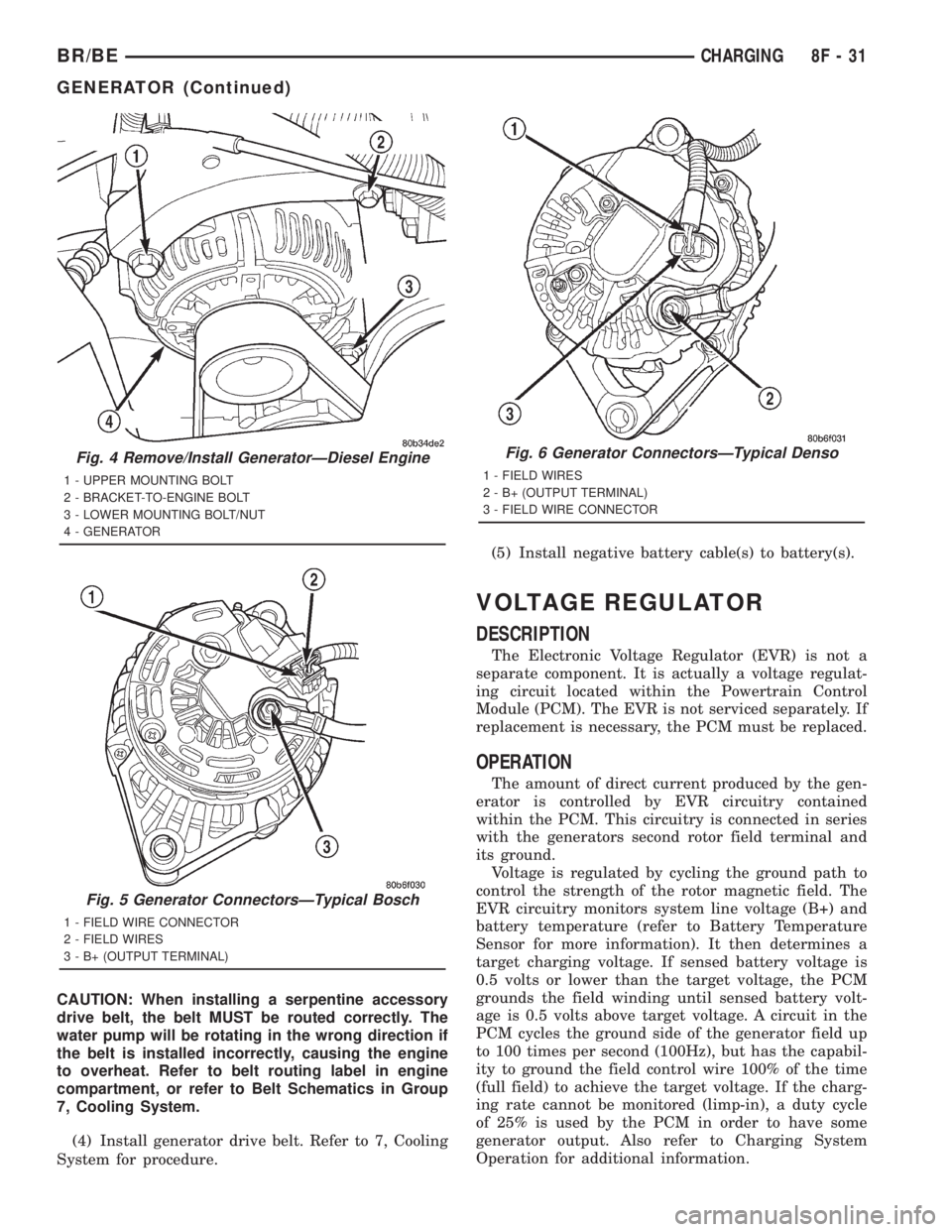
Fig. 4 Remove/Install GeneratorÐDiesel Engine
1 - UPPER MOUNTING BOLT
2 - BRACKET-TO-ENGINE BOLT
3 - LOWER MOUNTING BOLT/NUT
4 - GENERATOR
Fig. 5 Generator ConnectorsÐTypical Bosch
1 - FIELD WIRE CONNECTOR
2 - FIELD WIRES
3 - B+ (OUTPUT TERMINAL)
Fig. 6 Generator ConnectorsÐTypical Denso
1 - FIELD WIRES
2 - B+ (OUTPUT TERMINAL)
3 - FIELD WIRE CONNECTOR
BR/BECHARGING 8F - 31
GENERATOR (Continued)
Page 729 of 2889
(CTM) from the CTM connector receptacle. Reconnect
the battery negative cable. Turn the ignition switch
to the On position. With the washer button
depressed, check for battery voltage at the washer
switch sense circuit cavity of the instrument panel
wire harness connector (Connector C1) for the CTM.
If OK, proceed to the diagnosis for the wiper relay.
(Refer to 8 - ELECTRICAL/WIPERS/WASHERS/
WIPER RELAY - DIAGNOSIS AND TESTING). If
not OK, repair the open washer switch sense circuit
between the CTM and the multi-function switch as
required.
CLEANING - WIPER & WASHER SYSTEM
WIPER SYSTEM
The squeegees of wiper blades exposed to the ele-
ments for a long time tend to lose their wiping effec-
tiveness. Periodic cleaning of the squeegees is
suggested to remove any deposits of salt or road film.
The wiper blades, arms, and windshield glass should
only be cleaned using a sponge or soft cloth and
windshield washer fluid, a mild detergent, or a non-
abrasive cleaner. If the wiper blades continue to
leave streaks, smears, hazing, or beading on the
glass after thorough cleaning of the squeegees and
the glass, the entire wiper blade assembly must be
replaced.
CAUTION: Protect the rubber squeegees of the
wiper blades from any petroleum-based cleaners,
solvents, or contaminants. These products can rap-
idly deteriorate the rubber squeegees.
WASHER SYSTEM
If the washer system is contaminated with foreign
material, drain the washer reservoir by removing the
front washer pump/motor from the reservoir. Clean
foreign material from the inside of the washer reser-
voir using clean washer fluid, a mild detergent, or a
non-abrasive cleaner. Flush foreign material from the
washer system plumbing by first disconnecting the
washer hoses from the washer nozzles, then running
the washer pump/motor to run clean washer fluid or
water through the system. Plugged or restricted
washer nozzles should be carefully back-flushed
using compressed air. If the washer nozzle obstruc-
tion cannot be cleared, replace the washer nozzle.
CAUTION: Never introduce petroleum-based clean-
ers, solvents, or contaminants into the washer sys-
tem. These products can rapidly deteriorate the
rubber seals and hoses of the washer system, as
well as the rubber squeegees of the wiper blades.CAUTION: Never use compressed air to flush the
washer system plumbing. Compressed air pres-
sures are too great for the washer system plumbing
components and will result in further system dam-
age. Never use sharp instruments to clear a
plugged washer nozzle or damage to the nozzle ori-
fice and improper nozzle spray patterns will result.
INSPECTION - WIPER & WASHER SYSTEM
WIPER SYSTEM
The wiper blades and wiper arms should be
inspected periodically, not just when wiper perfor-
mance problems are experienced. This inspection
should include the following points:
(1) Inspect the wiper arms for any indications of
damage, or contamination. If the wiper arms are con-
taminated with any foreign material, clean them as
required. (Refer to 8 - ELECTRICAL/WIPERS/
WASHERS - CLEANING). If a wiper arm is damaged
or corrosion is evident, replace the wiper arm with a
new unit. Do not attempt to repair a wiper arm that
is damaged or corroded.
(2) Carefully lift the wiper blade off of the glass.
Note the action of the wiper arm hinge. The wiper
arm should pivot freely at the hinge, but with no
side-to-side looseness evident. If there is any binding
evident in the wiper arm hinge, or there is evident
side-to-side play in the wiper arm hinge, replace the
wiper arm.
CAUTION: Do not allow the wiper arm to spring
back against the glass without the wiper blade in
place or the glass may be damaged.
(3) Once proper hinge action of the wiper arm is
confirmed, check the hinge for proper spring tension.
Remove the wiper blade from the wiper arm. Either
place a small postal scale between the blade end of
the wiper arm and the glass, or carefully lift the
blade end of the arm away from the glass using a
small fish scale. Compare the scale readings between
the right and left wiper arms. Replace a wiper arm if
it has comparatively lower spring tension, as evi-
denced by a lower scale reading.
(4) Inspect the wiper blades and squeegees for any
indications of damage, contamination, or rubber dete-
rioration (Fig. 1). If the wiper blades or squeegees
are contaminated with any foreign material, clean
them and the glass as required. (Refer to 8 - ELEC-
TRICAL/WIPERS/WASHERS - CLEANING). After
cleaning the wiper blade and the glass, if the wiper
blade still fails to clear the glass without smearing,
streaking, chattering, hazing, or beading, replace the
wiper blade. Also, if a wiper blade is damaged or the
squeegee rubber is damaged or deteriorated, replace
8R - 6 WIPERS/WASHERSBR/BE
WIPERS/WASHERS (Continued)
Page 757 of 2889
Component Page
Map Lamps.......................... 8W-49
Outboard Clearance Lamp............... 8W-50
Outboard Headlamp................... 8W-50
Outboard Identification Lamp............ 8W-50
Output Speed Sensor................... 8W-31
Overdrive Switch...................... 8W-31
Overhead Console..................... 8W-49
Oxygen Sensors....................... 8W-30
Park Brake Switch.................. 8W-40, 50
Park/Neutral Position Switch.......... 8W-30, 51
Park/Turn Signal Lamp................. 8W-52
Passenger Airbag On/Off Switch.......... 8W-43
Passenger Airbag...................... 8W-43
Power Distribution Center............... 8W-10
Power Mirror Switch................... 8W-62
Power Mirror......................... 8W-62
Power Outlet......................... 8W-41
Power Seat Front Vertical Motors......... 8W-63
Power Seat Horizontal Motors............ 8W-63
Power Seat Rear Vertical Motor........... 8W-63
Power Seat Switch..................... 8W-63
Power Window Motors.................. 8W-60
Powertrain Control Module.............. 8W-30
PTO Switch.......................... 8W-30
Quad High Beam Relay................. 8W-50
Radio Choke Relay..................... 8W-47Component Page
Radio............................... 8W-47
Remote Radio Switch................... 8W-47
Seat Belt Switch...................... 8W-40
Seat Heat Interface Module.............. 8W-63
Security Relay........................ 8W-39
Speakers............................ 8W-47
Speed Control Servo................... 8W-33
Speed Control Switch................... 8W-33
Splice Information..................... 8W-70
Tail/Stop/Turn Signal Lamp.............. 8W-51
Tailgate Lamp........................ 8W-51
Throttle Position Sensor................ 8W-30
Trailer Tow Connector.................. 8W-54
Trailer Tow Relay...................... 8W-54
Transmission Control Relay.............. 8W-31
Transmission Solenoid Assembly.......... 8W-31
Turn Signal/Hazard Switch.............. 8W-52
Underhood Lamp...................... 8W-44
Visor/Vanity Lamp..................... 8W-44
Washer Fluid Level Switch.............. 8W-40
Water In Fuel Sensor................... 8W-30
Wheel Speed Sensors................ 8W-34, 35
Windshield Washer Pump............... 8W-53
Wiper Motor Relay..................... 8W-53
Wiper Motor.......................... 8W-53
BR/BE8W-02 COMPONENT INDEX 8W - 02 - 1